-
Senior Member

Congrats on getting the IRS diff installed. It's a heavy bugger, and not easy to install solo IMHO. Nice work.
Chris
Coupe complete kit delivered: 4/22/24.
Build Thread. Coyote. T-56. IRS w/3.55. Wilwoods. PS. HVAC. Side windows.
MK4 Complete kit.
Build Thread Index. Delivered: 10/15/2020. Legal: 7/25/23. Coyote Gen3. TKO600 (0.64 OD). IRS w/3.55. PS. Wilwoods. Sway bars. This build is dedicated to my son, Benjamin.
Build Thread.
-
Post Thanks / Like - 1 Thanks, 0 Likes
-
Thanks Chris!
I have to come clean about my progress...I've been taking my sweet time on the Aluminum panels for a variety of reasons...mostly because I don't want to get ahead in my build only to find that my rivet location gets in the way of something much later in my build ") I dread the out-of-place rivet, or an extra hole...It seems that the most straightforward jobs require the most diligence. I noticed this for the panels that already had "Tech Screw" holes. For example, I wanted to space the rivets in my F-panels (jeesh) so that when I rivet the brake line brackets, they don't look like an afterthought
I dread the out-of-place rivet, or an extra hole...It seems that the most straightforward jobs require the most diligence. I noticed this for the panels that already had "Tech Screw" holes. For example, I wanted to space the rivets in my F-panels (jeesh) so that when I rivet the brake line brackets, they don't look like an afterthought
R F-panel drilled.jpg
It was an easy decision to instead install the IRS, fit the suspension arms, try to find the "just right" shim thickness instead of off-the-shelf washers, etc. 
Craig C
-
Post Thanks / Like - 0 Thanks, 1 Likes
-
Front lower suspension arms and power steering rack
I installed my front lower suspension arms today. The installation itself wasn't any big deal, but I did manage to shim the gaps to my liking
left L front lower suspension arm.jpg right R front lower suspension arm.jpg
The lesson being: Yes, reach out for help and guidance, but do your build your way -- ultimately, you have to feel good about your product!
Since I was feeling good, I decided to install the power steering rack. I was mindful of the lessons learned from other builders, so I made sure the mounting tabs could accept the bushing and spacer width by gently spreading the mounts apart with a simple all-thread spreader...then I taped up the frame where I thought I might scratch it -- good planning! It went in easily, but still had to tilt everything just right...
power rack installed.jpg
Craig C
-
Post Thanks / Like - 0 Thanks, 1 Likes
-
Big Wilwood rotors on IRS hubs
I couldn't help myself ... I just had to install my rear Wilwood rotors, 'cause they just look cool 
IRS big rotors.jpg
They're also much bigger looking in person after seeing so many previous build threads...
Craig C
next update: installing the rear brake calipers...
-
Post Thanks / Like - 0 Thanks, 1 Likes
-
Rear Wilwood calipers installed
Here's the rear Wilwood calipers installed:
rear Wilwood calipers installed.jpg
As others have done, I wanted to share my shim settings -- I only needed one set of shims radially, and I used no shims for axial adjustments.
Other observation: the e-brake caliper pads are very snug on the rotors. I suspect this won't be an issue once the rotor coating is burnished off from the overall pad / rotor bedding procedure (with instructions from Wilwood in every box!).
Craig C
-
Post Thanks / Like - 0 Thanks, 1 Likes
-
Wilwood pedal box prep
Hey Y'all,
I decided to do other small jobs this weekend, since it's going to be hot again...I started with the pedal switch prep: holes marked, punched, and initial pilot
Wilwood pedal switch prep.jpg
Drilled Wilwood pedal switch holes drilled.jpg switch brackets mounted...ooops Wilwood pedal switch brackets installed.jpg
This is why I prefer to mock-up the parts into assemblies: there wasn't enough length on the switches to actuate at the preferred pedal position...plus the Build Manual had a picture
Correctly mounted Wilwood pedal switch brackets installed(2).jpg with switches installed Wilwood pedal switches installed.jpg
Happy Building!
Craig C
-
Post Thanks / Like - 0 Thanks, 3 Likes
-
Mock-up of pedal box and steering shafts
Hey Y'all,
More small jobs this weekend...Wilwood Pedal Box and steering shaft mockup...here's the dimples drilled into the lower and mid shafts
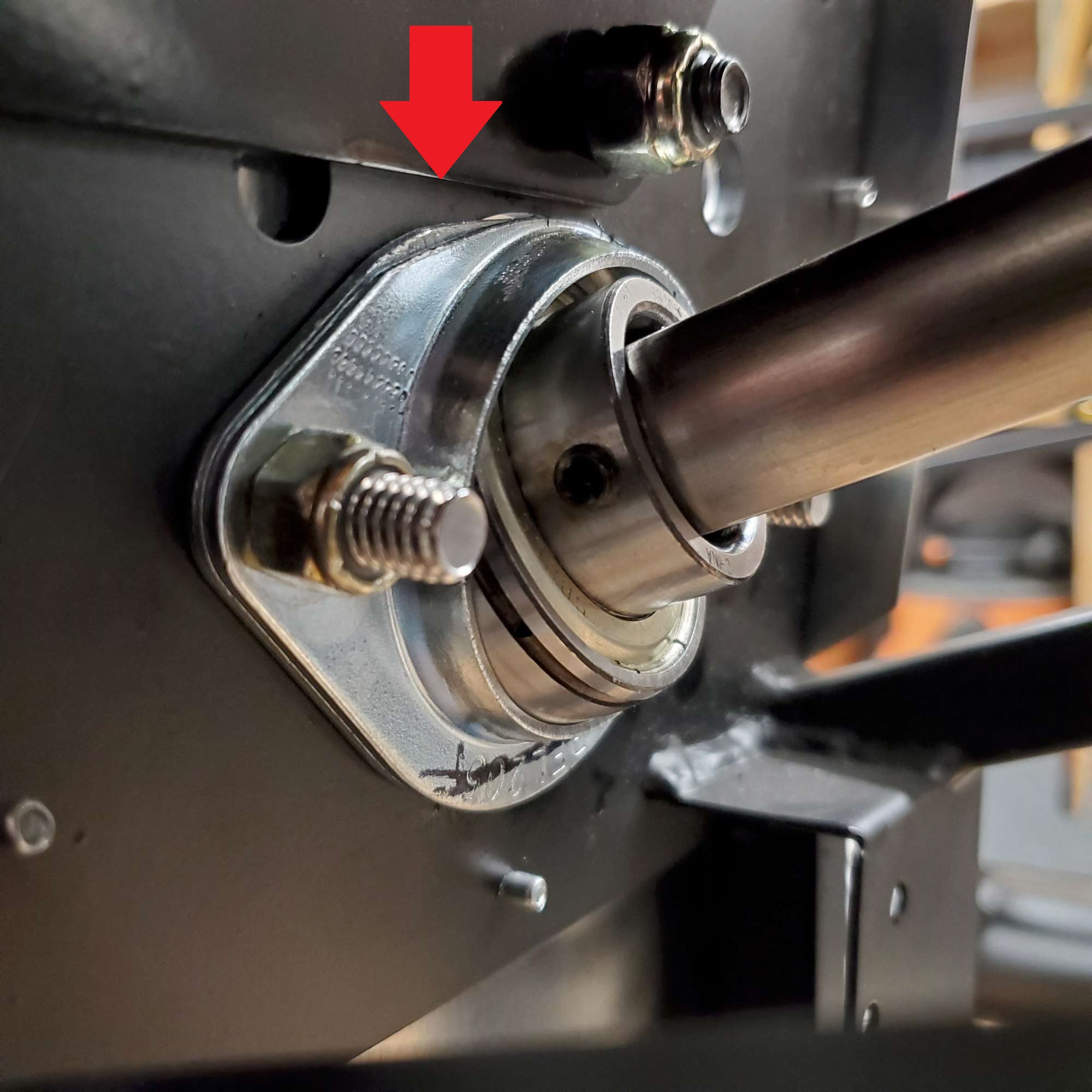
mid steering shaft prepped.jpg so far so good...following the instructions, then I came across the issue I think everyone encounters -- lower shaft is too long and protrudes into the lower u-joint:
lower steering shaft too long.jpg
Is the remedy to simply install the spherical bearing flange on the inside of the footbox frame reinforcement ? Here is my installation, per the Build Manual possible remedy for lower steering shaft too long(2).jpg
Feedback appreciated!
Craig C
-
Post Thanks / Like - 0 Thanks, 1 Likes
-
Mock-up of pedal box and steering shafts (con't)
I suppose the other option is to trim the end of the lower steering shaft to fit...
Anyway, I couldn't help myself to put on the steering wheel so I could sit in the chassis and make vroom-vroom noises
view of steering shaft assembly.jpg view of mocked up pedals and steering wheel.jpg
Happy Building!
Craig C
-
Post Thanks / Like - 0 Thanks, 1 Likes
-
Senior Member


Originally Posted by
cc2Arider

Thanks for this. For those that are following along, I decided to do mine tonight as well. If you use the switch brackets to make the hole, be aware that they fit differently on the other side. So, I used my first one as a template and snugged it up nice and tight. Drilled my hole and put it on the other side. It was 1/8th of an inch off (maybe a 1/16th). Regardless, it didnt fit. I ended up grinding the end until the holes lined up and I could snug it up. On the second one, I was not so militant about pushing it all the way to the back and it fit first time through. Anyway, not to hijack your post!~ Thanks for posting, it encouraged me to stop mucking with the DS footbox and actually make some progress!
Dan
-
Post Thanks / Like - 1 Thanks, 1 Likes
-
Hi Dan,
Thanks for the feedback! I, too, smoothed the tabs a bit with my belt sander. I didn't notice the fitment issues as much because I wanted to smooth those sharp edges on the laser cut parts (noticing that the cast Al parts had a nice radius)...
Craig C
-
Do not put the steering wheel hub on too tightly. You will need to take it off and it can get stuck without much effort.
20th Anniversary Mk IV, A50XS Coyote, TKO 600, Trunk Drop Box, Trunk Battery Box, Cubby Hole, Seat Heaters, Radiator hanger and shroud.
-
Post Thanks / Like - 1 Thanks, 2 Likes
-
Senior Member
Originally Posted by
cc2Arider
Is the remedy to simply install the spherical bearing flange on the inside of the footbox frame reinforcement ?
Feedback appreciated!
Craig C
Hi Craig. Sounds like you're enjoying this part of the build--I did as well, one of my favorite parts. If you can't get the needed clearance with the bearing on the outside of the FB, I wouldn't hesitate to put it on the inside. You'll likely need to grind the top portion of the flange bearing to provide clearance for the lower right mounting hole of the pedal box rear bracket. I would hesitate, however, before cutting the steering shaft. That should not be needed.
Chris
Coupe complete kit delivered: 4/22/24.
Build Thread. Coyote. T-56. IRS w/3.55. Wilwoods. PS. HVAC. Side windows.
MK4 Complete kit.
Build Thread Index. Delivered: 10/15/2020. Legal: 7/25/23. Coyote Gen3. TKO600 (0.64 OD). IRS w/3.55. PS. Wilwoods. Sway bars. This build is dedicated to my son, Benjamin.
Build Thread.
-
Post Thanks / Like - 1 Thanks, 1 Likes
-
Originally Posted by
Railroad
Do not put the steering wheel hub on too tightly. You will need to take it off and it can get stuck without much effort.
Thanks Railroad! Yes, it is barely on there at the moment...just barely contacting the flats machined into the shaft. I need to keep that hub pristine so I can send off to TJ for some turn signal treatment 
Craig C
-
Originally Posted by
460.465USMC
Hi Craig. Sounds like you're enjoying this part of the build--I did as well, one of my favorite parts. If you can't get the needed clearance with the bearing on the outside of the FB, I wouldn't hesitate to put it on the inside. You'll likely need to grind the top portion of the flange bearing to provide clearance for the lower right mounting hole of the pedal box rear bracket. I would hesitate, however, before cutting the steering shaft. That should not be needed.
Thanks Chris! You saved me the hassle of digging thru lots of build threads Not that I mind that too much (kinda neat seeing how others approached their builds), but rather tedious to find the exact thread that I'm searching for...
Appreciate the feedback!
Craig C
-
Post Thanks / Like - 0 Thanks, 1 Likes
-
Steering spherical flange bearing bracket -- take 2
-
Post Thanks / Like - 0 Thanks, 1 Likes
-
Heater/Defroster installation -- deep dive (part1)
For those who have already learned this -- apologies. For those interested in my observations of the heater/defroster installation issues -- read on!
General observation: The heater/defroster unit is pretty simple...after all it seems to be designed for the "Hot Rodder", and we're just adapting this to our Roadsters. Fair enough...it serves its purpose and nothing more. It is because we're adapting it to our builds that reveals the 1st issue --> The unit must be disassembled to "clam-shell" install it on the firewall. It has to sandwich the firewall panel between the core/plenum part, and the motor housing part.
Here is the problem: There is one screw that can't be accessed well to disassemble the unit properly. I had to unscrew both halves of the motor housing to get the motor/fan assembly out-of-the-way, then I had to drill/dremel a couple of access holes in the bottom motor housing to remove it from the core/plenum housing. Here's a picture of my efforts...
defroster-heater screw access holes needed in motor housing.jpg Here's an axial view defroster-heater screw access holes needed in motor housing(2).jpg
With the access needed to extract that last screw, the two main housing parts can be separated...then you can install the unit onto your firewall (already cut per the template instructions...which brings me to another observation --> you can print the template from the instructions, but select "real size" and it will print "to-scale" (or very close to it )
Installation onto firewall:
1) temporarily hold or affix core/plenum unit in the space normally reserved for the glove box
2) you will then need to affix the lower motor housing, through the firewall screw holes, to the core/plenum unit defroster-heater core-plenum and lower motor housing installed onto firewall.jpg
3) install the motor, with fan, and the vibration rubber cushion onto the lower motor housing
4) install the other motor rubber cushion onto the top motor housing
5) then mount the top motor housing onto the lower motor housing and affix this to the core/plenum unit defroster-heater core-plenum and both motor housings installed onto firewall.jpg
6) lastly screw the two motor housing parts together
Craig C
Last edited by cc2Arider; 09-05-2023 at 04:46 PM.
Reason: added missing step
-
Post Thanks / Like - 0 Thanks, 1 Likes
-
Heater/Defroster installation deep dive - part2
Here's some installed pictures just to give you perspective where this unit fits or "lives" in the Roadster --> for those wondering...you can see why FFR says that this unit does not integrate with the glovebox 
defroster-heater installed onto firewall perspective1.jpg defroster-heater installed onto firewall perspective2.jpg defroster-heater installed onto firewall perspective3.jpg defroster-heater installed onto firewall perspective4.jpg
In part 3, I'll show you what I had to do to repair the flimsy screw threads on the core/plenum housing
In the mean-time, Happy Building!
Craig C
-
Post Thanks / Like - 0 Thanks, 1 Likes
-
Heater/Defroster installation deep dive - part3
Since the heater box plastic housing apparently wasn't designed to be taken apart and adapted like our Roadsters require, it's hardly a wonder that the plastic threads failed upon disassembly -- they appear to be one-time-assembly manufacturing...
I decided to make them machine screw capable instead. My 1st attempt was to simply use an 8-32 rivnut -- Fail! There wasn't enough plastic around the perimeter of the rivnut head and there was an overlap thickness issue where I wanted to install it (stock location). I thought of another way. Here's what I did:
repairs to heater box threaded mounting holes.jpg
The red circled areas show what I think is called a j-nut...it simply sandwiches around the plastic where you want it. This added strength to the backside at the expense of having to perform dremel surgery to install it. I essentially cut installation slots into the plastic. Next, I sealed them up with epoxy compatible with plastic (since the heater box appears to be sealed with the stuff anyway)
For the holes in the top area, I'll try to rivnut those. You can see that I left the undeformed steel ones in there for now, but I ordered "softer" Aluminum rivnuts in an attempt to try again on the plastic. If those don't work, then my last choice is using wellnuts. Those are like a rivnut, but they use a molded rubber sleeve to accomplish the same thing as the rivnuts. They're used on motorcycles to good effect on less sturdy things, like polycarbonate windscreens attached to fiberglass body work )
I hope my experience on this helps the next builder who has issues putting in the heater/defroster box
Good Luck and Happy Building!
Craig C
-
Post Thanks / Like - 0 Thanks, 1 Likes
-
More firewall panel prep -- my OCD kicks in!
While waiting for some Aluminum rivnuts, I decided to jump into actually drilling into the frame -- a task that I've dreaded because I don't want to make a mistake
In a previous post, I had cut out the firewall panel to initially mock-up the heater/defroster box. This was good practice because...well...I couldn't stand the assembly holes already drilled into the firewall panel from shipment. No matter how many geometric combinations I tried, I couldn't "mask" the fact that they weren't installed for esthetic reasons
I decided to provide FFR Metal some business and purchased the thick firewall panel for my "final" install. The quality is excellent. The cut lines exactly match the FFR piece, except for one small area that I needed to trim up. It appears to be 11 gauge -- pretty beefy! I couldn't cut it with my shears or snips, so I used a holesaw on my drill press and bought myself a "burp-saw". This little dynamo is air powered and did the job well. I used a portable belt sander, otherwise known as a power-file, to clean up the edges for the openings I cut. Then I took my time with hand files.
The powdercoater recommended that I scuff the surface with a DA sander in lieu of abrasive blasting, so I did that. Here's what it looked like before actually drilling into the frame:
thicker firewall prepped for drilling into frame.jpg
I drilled two holes on opposite corners to check my work and initially locate the panel. Darn! first mistake...one hole was off a little 
Ok...no worries, I'll recover by clamping the panel where I want it, and simply drill thru the already drilled panels to serve as a drill guide! So far, so good. You can see the slightly offset hole and the marks where the speedscrew was used on the stock panel (I wanted to see how far off they were from my pattern)
first few firewall holes drilled into the 2x2 frame.jpg
Here's an up-close look at the mistake. Hard to believe an offset of less than 1/16" would cause me grief...oh well...that's me...
detailed zoom in of misaligned hole.jpg
Here's the job about halfway done. After obsessing about the proper spacing and geometric symmetry, I was also pleasantly surprised that the rivet holes are "centered" in the chassis, too
halfway done drilling for firewall into 2x2 frame tube.jpg
I was feeling pretty "frisky" at my success, so I decided to take on another "OCD" thing that was bothering me for a while. The short vertical 3/4" tubes that connect to the 2x2" firewall tube are not in the same vertical plane, and this really bothered me. In fact, you can see a picture in the build manual where the panel deforms under the pressure of the installed rivets. I wanted to do something more to my liking...
I had some genuine Boeing Al scrap panel that I had been saving for decades that I finally put to good use. I made shims out of them. Here is the passenger side:
added Al sheet as shim - passenger.jpg
I could just get a drill in there and looks like a rivet gun will fit, too
still had room for drill and eventually rivet gun - passenger side firewall vertical tube.jpg
and here's the Driver's side
added Al sheet as shim - driver.jpg
It's finally been nice weather here...good times in the garage building my Roadster -- it was an excellent weekend!
Craig C
-
Post Thanks / Like - 1 Thanks, 1 Likes
-
More panel fitment OCD
I've been trudging along in my engine bay/footbox panel installation with a pattern of: thinking, fitting, thinking, bending, thinking, shaping, etc
I'm gonna say something nice about the FFR Al panels: They are nicely cut! I even like the small marks left for the person doing the panel bending. This is where I need to provide some "constructive" feedback to FFR...
Please bend the panels on the marks intended by the designer -- they will fit better that way!
OK...got that out of my system. Here's some other learning. The A-panel to engine bay inner panels have not fit well for my chassis and I think a part of it is a misunderstanding of the way they are intended to fit together. Case in point, if you examine the pictures in the Build Manual, you'll see that the Passenger and Driver's side inner engine bay panels appear to be installed on the cockpit side of the A-panel flanges. I believe this is not the best fitment considering how difficult it is to put a "z" bend in that A-panel. Here's a picture looking up from the garage floor to that joint: A-panel to passenger inner engine panel to passenger floor panel poor fitment.jpg
I decided to put the flange on the other side and am getting much better fitment: A-panel to passenger inner engine panel to passenger floor panel better fitment.jpg sorry for the bad picture A-panel to passenger inner engine panel to passenger floor panel better fitment2.jpg
I drilled into the large main frame tubes and got a good result. Drill went in square and the clecos fastened well. Also note the better panel fitment drilled into large frame tube for first time.jpg
While I've complained about the Passenger-side fitment, the real problem was with the Driver's side inner engine bay / footbox panels. They appeared to be bent "too much". I had to soften the bend creases on both panels geometric planes to get a respectable fit. It's getting better! Here's a wider view of the improved fitment: more a-panel to inner engine bay foot box panels.jpg
That's enough on this topic now for sure. Of course feedback is welcome!
Craig C
-
Post Thanks / Like - 0 Thanks, 1 Likes
-
Trunk and Hood Hinges media blasted and painted
Hey Y'All,
While I was waiting for my F-panels to return from powder-coating (and needing a break from my panel fitment routine). I had the trunk and hood stainless-steel hinges media blasted and then I painted them. They turned out decent. Here's the trunk hinges (note the paint drip near the hinge pivot ) media blasted and painted trunk hinges.jpg
And here's the hood hinges media blasted and painted hood hinges.jpg No drips this time!
Craig C
-
Post Thanks / Like - 0 Thanks, 1 Likes
-
Finally got my F-panels back from powder coating!
Hey Y'All,
It's been a long time coming, but I finally got my F-panels back from powder-coating, and I like the way they look powder-coated F-panels.jpg
I also had the firewall coated, and I'll put that on later...powder-coated firewall.jpg Since this was a thicker panel, and I wasn't sure how think the finished powder would be, I had the powder coater mask off a 1/4" strip so that the bulb-seal wouldn't deform the metal insert so much (when that time comes to install it) ...
The color is Hilltop Silver from Prismatic Powders. Very similar (almost identical) to my Wilton bench vise finish...unexpected synchronicity
Craig C
Next: Finally putting together the front end!!
-
Post Thanks / Like - 0 Thanks, 1 Likes
-
Heater Box repair -- the missing post :)
Hey Y'all,
I looked down thru my thread and realized that I never did post an update on my Heater Box thread repair. Bummer...I get "into the zone" and forget to share what I've been up to...
Long-story-short: I waited for the Aluminum rivnuts and they didn't work any better on some similarly drilled and constructed plastic. The heads would deform slightly after being fully seating, and I found out that rivnutting (is that even a word?) into plastic is very dependent on the rivnut being a tight fit into the hole. By then, I realized my holes were already too big for any reasonable-sized rivnuts, so I changed direction to "wellnuts". These are rubber with a brass threaded insert and much easier to work with...perhaps at the expense of not being as tough as the metal rivnuts.
Anyway, here's a picture of the result. Wellnuts on the top and the metal clips on the bottom. I think it'll be a decent compromise...only time will tell.
Heater box thread repair.jpg
Craig C
-
Post Thanks / Like - 1 Thanks, 1 Likes
-
1st panels installed -- finally!
Hey Y'all,
As promised, I finally got my F-panels ready for installation. My technique: pre-fit panels, note where to protect and add blue tape, silicone the joints (thinly), cleco into place, start exchanging clecos for rivets. Here's mid-progress picture: installing passenger side F-panel.jpg
This was my attempt to try to minimize scratches caused by the tool my attempt to minimize rivet tool scratches.jpg not sure it was effective, but made me feel better...
Finished panels:
finished passenger side F-panel.jpg finished driver side F-panel.jpg
I chose "large head", black painted, multigrip rivets since I wanted a contrast/tie-in to the frame visually. Not everybody's preference, I know, but I like the look
Next update:
Front suspension
Craig C
-
Post Thanks / Like - 0 Thanks, 1 Likes
-
Senior Member

Looks good with the rivets contrast. I had issues with some panels as well, especially inside driver side, but I have the "A" panel on the inside as well, it did fit better.
-
Post Thanks / Like - 1 Thanks, 1 Likes
-
Thanks for the confirmation Lance
Craig C
-
Front suspension goes on
Hey Y'all,
I've been looking forward to getting my front suspension installed and got it knocked out over the weekend. Here's some pictures...
Installed upper A-arms installed front upper A arms.jpg
Exchanged grease nipple on passenger-side lower A-arm for the Breeze Battery relocation kit exchanged grease nipple for 90 deg to fit Breeze Battery Box.jpg
Installed front coil-overs installed front coil-overs.jpg
Installed front spindles to ball joints installed front spindles to ball joints.jpg
Check out how well the Energy Suspension ball joint polyurethane boot retains its shape Energy Suspension eurethane ball joint boot retains shape.jpg
Fun stuff!
Craig C
-
Post Thanks / Like - 0 Thanks, 1 Likes
-
Front hubs, rotors, calipers, and steering linkage
Hey Y'all,
More fun stuff! Installing the front hubs, rotors, calipers, and steering rod-ends...
After reading the cautionary tales of other's difficulties with the front hubs, I was a bit apprehensive, but mine went on without drama. I simply greased the spindle shaft and hub inner bearing races and wiggled it on with just the heel of my hands
Then used a little bit of anti-seize on the deformed threads of the hub nut and torqued with no issues. Yes, it was all 250 lb-ft, but I managed. Then came the rotors with the concentric ring and the Wilwood calipers with a few shims. One thing that I noticed while installing the pads: the 6-piston Wilwoods have a cast "bridge" between the two assembled caliper halves which means that pad replacement must entail caliper removal Oh well...
So here's the picture of the results front driver side hub, rotor, and caliper installed.jpg front passenger side hub, rotor, and caliper installed.jpg
Today I took great pride in installing the cotter pins properly (after doing a slap-dash job yesterday). Yeah, I know...cherish the little things Last thing was to measure the overall length of the steering assembly, make sure the rod-ends were turned out an equal number of times and install those...
One question: Did you use the locknuts already on the FFR power rack or did you use the lock nuts that came with the rod-ends? I just kept the ones on the rack as-delivered...
drivers ball joints, rod end, and cotter pins.jpg passengers ball joints, rod end, and cotter pins.jpg
Craig C
-
Post Thanks / Like - 0 Thanks, 1 Likes
-
Cockpit panel pre-fitment and odds-n-ends
Hey Y'all,
Since learning that the Al panels all seem to fit together like a puzzle, I decided to do some pre-fitting of the cockpit panels. Once again, the passenger-side seemed pretty good, but the driver's side panels have some of the bends slightly out-of-place -- this means thinking thru the tolerance stack-up and adjusting the overall fit, or deciding to take more drastic measures. I may decide to try to re-bend the locating tabs on the driver's side cockpit floor panel. If that doesn't work, then I'll simply cut one tab off and substitute for a new 90deg adapter piece that I'll rivet on...
Here's a picture of the fitting effort cockpit panel pre-fitment.jpg
Taking a break from the panel fitment, I decided to try my best at forming the brake lines. I chose seamless, annealed stainless steel tubing (pretty economical at Summit) for aesthetic reasons. I got a good hard-line flaring tool and cut off a 6" piece for testing. Here's my 1st effort at a double-flare double flared SS brake line test.jpg
Now...granted, this is just a sample of one, but I couldn't see any flaws, and if I can do it, you can too!
Feeling frisky, I then decided to make back-to-back purposeful 45 deg bends using my new Ridgid tubing bender ss brake line 45 bend test.jpg
If this is representative of what's to come, I'm excited to get on that job! Especially following the drudgery of Al panel fitment -- geez!
Oh well, back to the grind. After finding out that my passenger-side outer footbox panel didn't quite line-up with the outrigger frame tube, I decided to shim it with some spare panel stock. I got it to fit good, then clamped in place to start drilling Here's a picture before I started to drill into the frame. This is taken inside the footbox looking straight down at the frame outrigger tube... Al cut panel used as shim for passenger side outer footbox panel-to-outrigger-frame-riveting.jpg The edge thickness can be seen because I marked it with a red sharpie.
After drilling carefully with no issues and clecoing into place after each drilling effort, this is the result passenger side outer panel clecoed to outrigger frame tube.jpg Not bad...
Lastly, I decided to modify the FFR-supplied hard-line-to-flex-line brake brackets for the front brakes so that I can rivet to the top of the 3/4" square tubing instead of on the side where the F-panel is located. I marked the inside bend line with slight scoring from a hacksaw, then I used a bench-vise, a large crescent wrench to initiate the bend, and a ball-peen hammer to complete the 90 deg bend. Turned out well with no apparent cracks or issues. I'm pleased with the result FFR supplied brake line bracket bent 90 deg test.jpg
So...the theme of this post is "if you need a change-of-pace, just do it! Find something else useful and keep that motivation going"
Craig C
-
Post Thanks / Like - 0 Thanks, 1 Likes
-
Senior Member

45 degree double flare on stainless steel tubing??? Stainless tends to fatigue and crack when double flared, it should only be 37 degree single flared for AN fittings. If you want to use 45 degree double flares you're best to use steel or Nicopp tubing.
-
Post Thanks / Like - 0 Thanks, 1 Likes
-
-
Post Thanks / Like - 0 Thanks, 1 Likes
-
Fitting the Driver's side Footbox Panels
Hey Y'all,
Working on the Driver's side footbox panels a couple hours each worknight and most of the weekend days. The technique that I'm using is frustrating but not sure how else to do it: get a good reference, and fit the next panel. Make adjustments until reasonable, then go to the next panel. Pause and think about the plan ahead. Rinse and repeat. I haven't drilled any holes yet and am relying on lots of different clamps and a few clecos in the factory-drilled holes.
I knew this fitment would be a challenge and it has not disappointed in that regard but it's getting there slowly...
Here's a few pictures so far driver's side footbnox panel fitment1.jpg driver's side footbnox panel fitment2.jpg driver's side footbnox panel fitment3.jpg
I did realize that this is an opportunity to buy another tool. I think I'll get a protractor next so I'm not eye-balling the adjusted flange bends between fitment and readjustment steps.
Craig C
-
Post Thanks / Like - 0 Thanks, 1 Likes
-
Driver's Side Footbox Panel fitment (con't)
Hey Y'All,
More progress made this past week/weekend on my Driver's side footbox panels. My starting point of reference is what I'll call the "Driver's side Bulkhead", the thick steel panel for the steering shaft, brake pedal bracketry, etc.
Here's the drilled/cleco'ed front panel. Yeah, I got carried away with the rivet locations
driver's engine side footbnox panel fitment to bulkhead panel.jpg
That set the alignment for the inner panel, which allowed me to drill/locate that panel to the "A" frame panel
driver's engine side footbnox panel fitment to A panel2.jpg view from the cockpit driver's engine side footbnox panel fitment to A panel1.jpg.
Note the driver's floorpan tab is "on the other side". This just fit better for my panels -- your panels may fit better than mine. I just have to remember to put that floorpan panel in 1st, before the inner-side footbox panel during final assembly...I'll also need to file out some rivethead relief for the lowest rivet on the "A" frame panel, so that it doesn't interfere with the floorpan flange.
Next, I worked on the fitment of the inner panel to the firewall panel. This seems to result in a noticeable "gap" for some of the builders out there. I used a combination of metal forming tools to redo that corner, and I now have an acceptable "reveal" at that edge driver's engine side footbnox panel fitment to firewall panel.jpg
After all the fitting/fussing, I'm pleased with the fitment so far My methods/OCD may not be for everyone, but my main goal was to fit the panels so that they would fit together without requiring rivets to properly align the panels; i.e., I could just lay them in place and all the panels and flanges would align without the cleco or rivet clamping forces.
Craig C
-
Post Thanks / Like - 0 Thanks, 1 Likes
-
Senior Member

looking good. keep in mind that any small gaps can be filled w/ silicone or a small patch can be made as well for larger gaps. Most of this will be covered by sound mat and carpet anyway, so don't get too worked up about the gaps.
-
Post Thanks / Like - 1 Thanks, 1 Likes
-
-
Post Thanks / Like - 0 Thanks, 1 Likes
-
Senior Member
maybe too late at this point, but poor fitting panels are usually a result of misalignment of the panels themselves rather than the frame/bulkhead itself. I'd prefer to adjust the panels over making major modifications to the frame.
-
Post Thanks / Like - 0 Thanks, 1 Likes
-
Understood .. my brother pointed that out to me also. My reasoning was that I couldn't rivet those two panels together at the "usual" 3/8" distance from the edges without interfering with the bulkhead panel -- I'd either have to avoid that altogether or choose a drilling location that sandwiched both.
Believe it or not, but I wasn't actually worried about my choice...as compared to the first time I drilled into the frame for the F-panels, and then the round main tube frame for the footbox floor panels -- yikes!
Thanks for the feedback
Craig C
-
Post Thanks / Like - 0 Thanks, 1 Likes
-
Driver's side footbox outer panel fitment
Hey Y'all,
I spent some time this past week fitting my Driver's side outer footbox panel. Since choosing the front of the footbox as the reference point in 3d space, the outer footbox panel was fitting reasonably well, but I needed to make sure it would still fit well with the footbox floor properly located and fastened. I first aligned and fastened the floor to the front panel tab, and that properly set the outer panel in relation to the front panel and floor panel. With that corner set, I noticed a small gap to the "outrigger" tube (similar to the passenger-side lower outside panel).
My approach to address that gap was to use a spare panel which I cut to use as a shim. It worked well on the Passenger side, so I replicated the approach on the Driver's side. Here's some pictures...my plan driver's side outer footbnox panel fitment to outrigger round tube1.jpg checking the fit (this is looking straight down towards the Driver's side footbox floor. Notice the shim temporarily in place) driver's side outer footbox panel shim1.jpg picture of the floor joints driver's side footbnox floor fitment.jpg
So far...so good, so I fastened the floor panel to the main frame tube driver's side footbnox floor fitment to main frame tube.jpg then drilled/cleco'ed the outer panel to the floor flange and thru the "outrigger" tube driver's side outer footbnox panel fitment to outrigger round tube2.jpg. Here's another picture of the shim (looking down) driver's side outer footbox panel shim2.jpg
Just as on the Passenger side, I noticed that one of the pre-drilled holes for the outer panel "came back" into alignment on the 2x2 vertical frame post -- Nice!
Craig C
-
Post Thanks / Like - 0 Thanks, 1 Likes
-
Final adjustments for the Driver's side footbox top
Hey Y'all,
I still had to make some small adjustments to get everything to fit well on the Driver's side footbox top panels. Here's an adjustment I made to the outer two pre-drilled holes -- note the keyhole notches
driver's side outer footbnox to outer top panel fitment with correction.jpg
The last panel to fit was the top inner panel and that went pretty well. I still had a small gap to the firewall panel, but that was easily corrected with another shim
shims used on driver's side of firewall to get footbox top panels aligned.jpg
I'll devote some time this week to preparing these panels for powder coating...and on to the next task.
Craig C
-
Post Thanks / Like - 0 Thanks, 1 Likes
-
Mocking up brake hardline mounting tabs
Hey Y'all,
Instead of prepping panels for powder coating, I decided today to plan/fit/mockup my hardline brake mounting tabs at each wheelwell. I liked the stainless steel tabs provided by FFR, but I just bent them 90deg and added a combination of washers and locating shims to make them work with the stainless AN-3 bulkhead fittings that I plan to use to connect to the Wilwood flex lines (copied idea from Mike Bray). Here's a couple of pictures
passenger wheelwell looking inboard front brake passenger hardline mount mock-up1.jpg and looking outboard front brake passenger hardline mount mock-up2.jpg
The driver's side will be similar, but will use a bulkhead T fitting (on backorder from Earl's/Holley)
The rear tabs looked like they could be used flat. Here's some mock-up pictures
Driver's side rear rear brake driver hardline mount mockup.jpg Passenger side rear rear brake passenger hardline mount mockup.jpg
I think these will be in a good location considering the arc of the suspension movement, accessibility if I ever need to service them or fix leaks, etc. Did anyone consider these locations and change their mind because of some issue?
Appreciate the feedback!
Craig C
-
Post Thanks / Like - 0 Thanks, 1 Likes


 Thanks:
  Likes:


 Reply With Quote
