Back in July I discovered another thing that ford changed between Gen 13 and Gen 14 F150s. The vapor canister. As you can imagine Ford goes through great lengths to ensure that fuel vapors dont vent into the atmosphere. Our problem is the shape and frame mounting points change between generations of the F150.
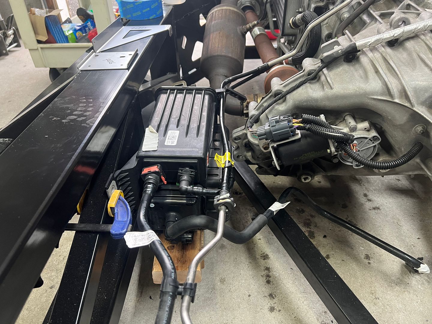
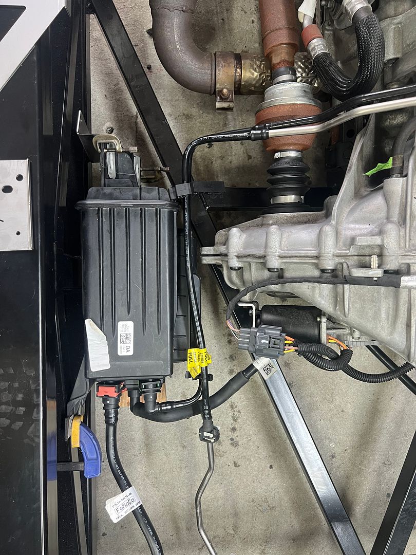
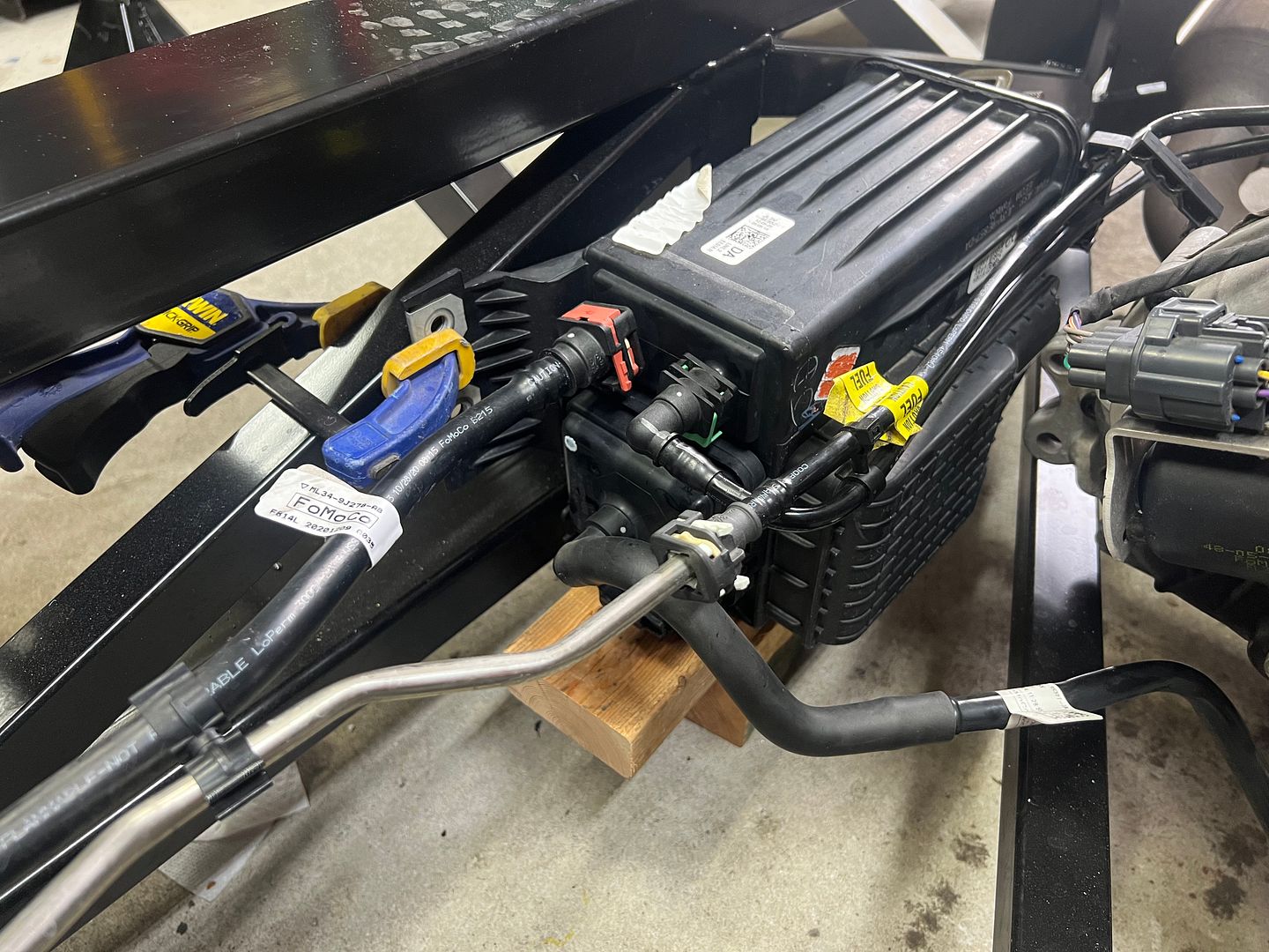
Here you can see how the canister tucks between the frame and transmission on the drivers side of the frame.
Here I have it clamped in place using the hardware and brackets that factory five provide that fit the Gen 13 F150.
I could sort of make it work maybe using a bunch of washers to adjust for the change in mounting angles between the frame and canister.
The rear mounts are pretty good I could make these work. Cutting and welding the factory five brackets was an option, but I dont know if I want the canister to live in this spot.
Like the wiring, I didnt have time to sort out an elegant solution to mount the canister so I just zip tied everything in place for SEMA.
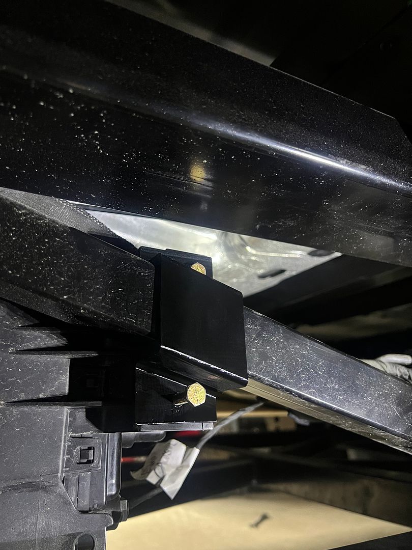
Since I love having a robot make stuff for me 3d printing to the rescue.
I printed a bracket that captures the frame for the rear mount .
Then made a two part bracket for the front mount.
This shows the gold prototype I used to verify my part dimension's before a few tweaks then making a final print for installation.
Check off another problem solved by the 3d printer.
XTF #2
build start date June 19 2023
GTM # 344
Build Start December 2010
First track day April 2013
This route is definitely faster than 3D printing or or CNCing a buck/mold. the down side is you don't have something you can sell on Etsy to other builders.
This route is definitely faster than 3D printing or or CNCing a buck/mold. the down side is you don't have something you can sell on Etsy to other builders.
Haha very true. The truck needs to be done for SEMA so i don't have time to play around sadly.
The other thing to consider is that Factory five will likely offer a turn key 2021 sooner kit if people ask for it. Else they will offer it as demand increases.
The work I have done is no big deal for factory five to Change in the turn key kit.
If you don't go off the rails building a crazy power plant or try to modify fords Gen 14 design back to a gen 13 design the build would likely take 1 month.
Now getting a truck ready for SEMA. I am sweating !!
This truck needs to be shaken down an ready for the desert in 6 weeks
XTF #2
build start date June 19 2023
GTM # 344
Build Start December 2010
First track day April 2013
So after finding that the pro power housing would not fit, I decided to see how it worked.
Here is the front view of the housing with the electronics removed.
Here is the back view
The right hand side of this housing actually is empty. Nothing in it but air. I can size down the housing and still enclose all of the electronics AND justify my 3D printer purchase. Win win.
Here is my first draft version of the front plate.
The Ford housing has a cover for the outlets, so I incorporated that into my faceplate.
My design uses all the hardware and gaskets from the Ford housing just for efficiencys sake.
So far so good. I think this is going to work.
Now I just need to add a few more details and the face plate will be done.
XTF #2
build start date June 19 2023
GTM # 344
Build Start December 2010
First track day April 2013
My experience with round tail light mounting was much easier. Did you consider cutting the original mounts out of the donor box and bonding them in place?
jim
My experience with round tail light mounting was much easier. Did you consider cutting the original mounts out of the donor box and bonding them in place?
jim
Actually Jim cutting out the tail lights would be a great solution as you quickly get OEM fit.. BUT a very expensive solution .
The aluminum bed of an f150 in pristine condition lists for 4-5 thousand dollars on EBAY. Im not sure if they actually sell for that amount, but even if it sold for $1000 those would be very expensive tail light buckets !!
When Im done with the bed Ill sell it as there are many folks who buy a badly damaged F150 and rebuild it with a nice good as new bed like mine.
XTF #2
build start date June 19 2023
GTM # 344
Build Start December 2010
First track day April 2013
With the basic design of the outlet plate for the pro power housing done. I figured now is a good time to see how it all fits together using the ford hardware and gaskets.
Here is the finished outlet plate from the front.
From the back you can see all the electronics installed.
I think its pretty obvious Ford had lots of wasted space in the housing so that they could have one housing for the F150 with pro power and two alternators as well as a high amperage solution for the F150 lightning in the same size cutout in the bed wall.
Now that the front works well I simply needed to design a rear cover to close the box up .
Again I wanted to re use the Ford hardware. So this is my solution
Its very water tight and sturdy.
And finally I need a flange to mount the housing to the bed.
And here it is all put together.
I still have a few minor details I am not happy with, but in general I think this will work. Ill reprint a few of the parts in high resolution to get thinner layer lines. If all goes well Ill install it this weekend.
XTF #2
build start date June 19 2023
GTM # 344
Build Start December 2010
First track day April 2013
I am confused. You put Lizard skin on the backside of the panels?
As an experienced pick-up owner I never hear structure noise from the cargo box, maybe they do not exist.
Bed liner will contribute somewhat to averting panel impact damage, but it will not be OEM truck-like. Light duty.
After two long term Tundras, I recently bought a Honda Ridgeline. The cargo box has SMC composite panels in the steel body. The OEM bedliner was not UV resistant and evaporated in spots leaving fiberglass exposed.
I removed all the panels and double coated them with Durabak-18 through Amazon. It comparison tested very well. It comes in colors and my gray matched the leather interior.
jim
Project Farm bedliner review: https://www.google.com/search?q=Proj...RY-Z0ObgY,st:0
I am confused. You put Lizard skin on the backside of the panels?
As an experienced pick-up owner I never hear structure noise from the cargo box, maybe they do not exist.
Project Farm bedliner review: https://www.google.com/search?q=Proj...RY-Z0ObgY,st:0
Yeah the side panels on the XTF are thin flat aluminum. The floor is thick flat aluminum. If you leave them alone they can vibrate. Over time the rivets could loosen and then they could vibrate. Sure maybe they are fine, but with the flat panels and rivet construction, it’s always good to go the extra mile to eliminate any chance of vibration.
Last edited by kabacj; 09-19-2023 at 09:10 PM.
XTF #2
build start date June 19 2023
GTM # 344
Build Start December 2010
First track day April 2013
The more I see people doing with 3D printers the more I want one.
Now to convince the wife I NEED one.
While Im not trying to crate domestic unrest. You need one. I cant tell you how many things I use the printer for. From making a housing like this, to printing a housing that makes the truck think the grill shutters are still attached to making holders for the shock remote reservoirs to making a replacement cap for a bearing cover that was lost.
Yes you need to consider the heat your part will deal with and strength of the plastic you are printing, but i have found with a little creativity and material choice you really can solve many problems that formerly were not in the realm of an weekend warrior.
Originally Posted by Namrups
Just keep in mind that the "printer" part of the equation is the easy part. Learning to design the part you want is much harder along with the fact that computer programs that allow you to do the design can be very expensive and have a steep learning curve.
Yes you are correct Scott, the printing part is the easy part. But you can get software that works well for free. Fusion 360 has a free version that will allow you to make everything I did, and you can get Solid works for 99 dollars a year. Both programs could draw this part easily.
I only started using fusion 360 for drawing stuff a few years ago and am 100% YouTube taught. I would encourage anyone who has the desire to put a little time into learning to take the plunge.
Crash, download fusion 360 and start to play around and see if you like the drawing part of this process. Once you can make the software do what you want, the world is your oyster.
My post makes it look like i fired these parts out first try in a few days, but i actually went through several iterations trying solutions and revising the design. Printer filament is super cheap and I set the printer going over night or when Im at work and I wake up or come home to a finished part.
The next frontier is making castings in aluminum from the plastic parts. I dont have a good problem to solve that needs this process yet, but Im sure Ill find one.
XTF #2
build start date June 19 2023
GTM # 344
Build Start December 2010
First track day April 2013
Hey John,
I don't know what your bedliner plan is but I highly recommend Raptor. I recommended it to Erik and he used it. I've been using it on the undersides of all the Cobra and Coupe bodies I've done for the past 3 years or so and love it! User friendly and creates a nice texture which you can vary with pressure or number of coats.
I have enjoyed following along!
Jeff
Hey Jeff Thanks! Yep I got the Raptor Liner as well. I saw how well Eriks turned out and clearly thats the best solution .
XTF #2
build start date June 19 2023
GTM # 344
Build Start December 2010
First track day April 2013
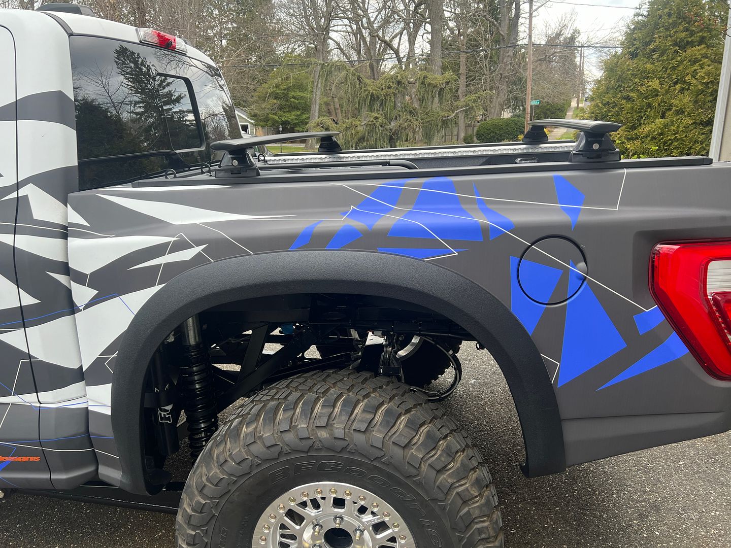
I was doing some suspension setup adjusting the limits of travel on the rear of the truck this weekend. The travel on this truck amazes me every time.
then fully compressed.
I want to make sure that I have every last bit of travel available in the setup before I start off road testing.
With the super long travel its important that I have located wires and hoses out of the way and also allowed for suspension movement in the brake lines and wires.
XTF #2
build start date June 19 2023
GTM # 344
Build Start December 2010
First track day April 2013
You probably have already, but don't forget about articulation. With off road and solid rear axle suspension in particular the articulation can be extreme and can cant the rear tires greatly. Need to make sure there is plenty of clearance for that. Does this truck have sway bars?
You probably have already, but don't forget about articulation. With off road and solid rear axle suspension in particular the articulation can be extreme and can cant the rear tires greatly. Need to make sure there is plenty of clearance for that. Does this truck have sway bars?
Yep agree the twist of the rear suspension can move the tires quite a bit, but with this 4 link setup the travel is still inside the fenders. The tires tuck up in there nicely.
For the anti roll bars, yes we have them both front and rear.
I think they actually contribute quite a bit to how well the truck handles on the road. As shocking as it sounds this truck actually is a corner carver. Im not sure if its the spring rates, or the wider track or the anti roll bars, or all three combined. But XTF carves a corner much better than the stock F150. I honestly am shocked every time i take a corner quickly. A truck shouldnt be this flat and composed.
The front ARB is connected to the the xtf frame and its out of the way of any trail hazards.
For rock crawling , its probably best to disconnect both anti roll bars to allow free articulation.
In the desert, Im not sure. Maybe flatter cornering would be best.
The rear anti roll bar is out of the way of trail hazards except for during full suspension compression.
Here is how the arb looks during full extension.
The center section of the bar is barely bellow the differential
During full compression the arms do get a bit lower , so maybe they would hit a trail hazard . But you just did a really big jump to compress the suspension that far ha.
XTF #2
build start date June 19 2023
GTM # 344
Build Start December 2010
First track day April 2013
The rear? Not so much. Maybe a suggestion for FFR to try a rear ARB where the bar is actually up on the frame and only the links go up and down to the fixed points on the rear axle? Yes you need some room above and below the ARB, but it can be a straight piece of 4130 tube and it solves a lot of issues.
Also, be very careful using those single point jack stands. They do not handle lateral loads very well, if at all. I would not feel comfortable working under the truck with those.
I'm guessing the Fox Shox have a lot to do with how well the truck handles. Very happy to see FFR using those units. We dropped 3 seconds a lap (!) when we installed some custom Fox Shox on the FFR GTM race car.
Kind of a cliff hanger there. I hope you are using a high temp filament like ABS, Nylon, or ASA. If you print that out of PLA or PETG it's going to soften up and lose shape.
I am sure you have already done this, but since you stated that the truck will not function properly without that unit, I would think that would be important information for FFR to know and they should come up with some sort of fix for that? Doesn't look like that diagonal is doing much and may be able to be eliminated, but FFR should be able to come up with something "official". After all, these are the types of issues Beta users are supposed to identify and get remedied.
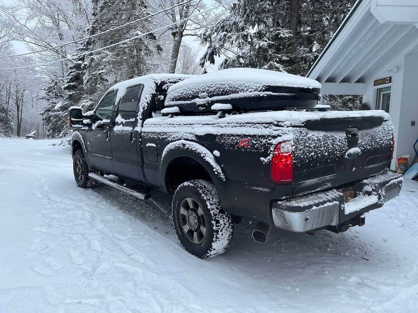
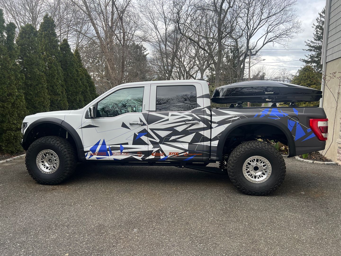
Now that the truck is in great shape from construction perspective with everything tidy like Ford intended, its time to add some accessories.
Our family are big skiers/snowboarders so we make many trips to northern Vermont every winter. I like using the ski carrier on the truck because it allows me to organize our gear and the pod is also waterproof. Plenty of trips start in the rain here at home and transition to snow up north.
Here is the setup on the F350.
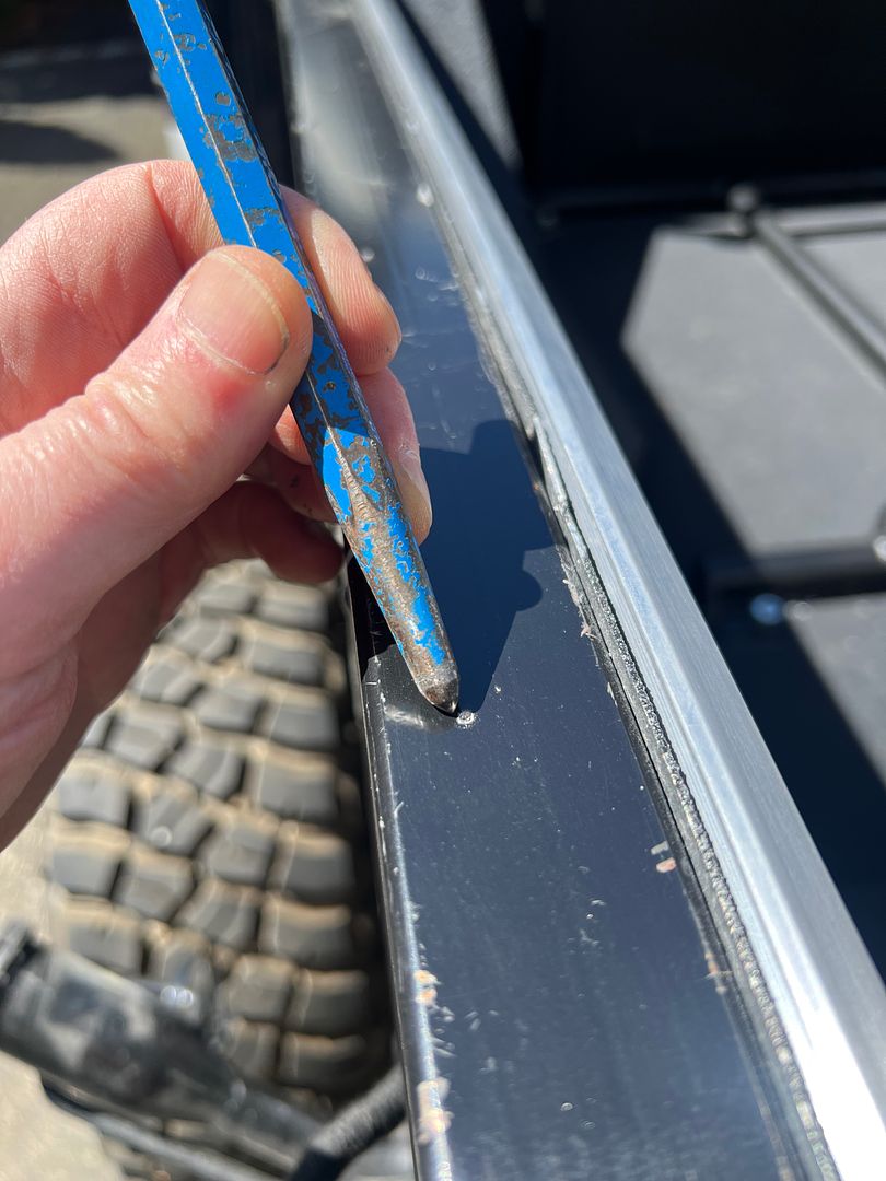
I purchased some T track rails from Yakima to mount on the XTF fenders.
Installation was easy.
First remove the fenders. I filled in the holes I was previously using to mount the fenders with some body filler.
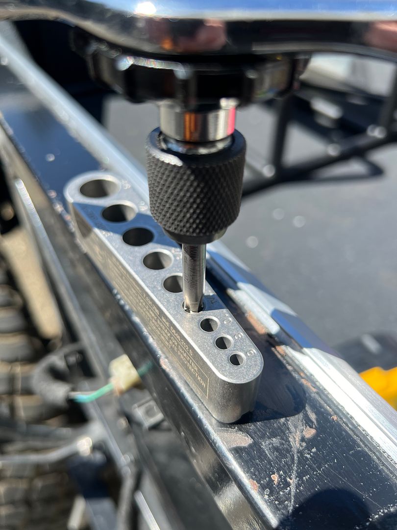
i marked all the holes using the T track rail as a guide. I put a fastener in all of the holes.
Drilled and tapped all the holes for 1/4 20 button head faseners.
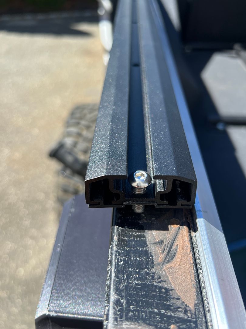
T tracks installed and the racks slide right in.
And we are done. The XTF with a Yakima GrandTour cargo box. Ready for some snow.
Last edited by kabacj; 04-07-2024 at 07:31 AM.
XTF #2
build start date June 19 2023
GTM # 344
Build Start December 2010
First track day April 2013
Just keep in mind that the "printer" part of the equation is the easy part. Learning to design the part you want is much harder along with the fact that computer programs that allow you to do the design can be very expensive and have a steep learning curve.
Heat inserts are okay if the forces are not trying too much to pull them straight out. I’m a huge fan of square nuts because they can be inserted into prints from any orientation, hexagonal nuts only go in flat. Design a hole into your part, pause the print before the first layer closing the hole, drop the nut in to have it fully enclosed.
Heat inserts are okay if the forces are not trying too much to pull them straight out. Im a huge fan of square nuts because they can be inserted into prints from any orientation, hexagonal nuts only go in flat. Design a hole into your part, pause the print before the first layer closing the hole, drop the nut in to have it fully enclosed.
Thanks AJ. Yeah i agree with your point.
My problem was that Im printing with ASA filament. Just keeping everything attached to the build plate and avoiding any warping required a preheat of the enclosure. Opening the enclosure and letting in a draft of cold air would surely make the print turn into a potato chip instantly .
Even pausing the print might be a problem based on how touchy the setup is . I get the enclosure up to 30 degrees Celsius (86 degrees F) and keep it there for the duration of the 4 hour print. That seems to avoid any warping.
When the print is finished if i am waiting there and open the enclosure as soon as the print is done I can hear the print pulling off the build plate with the draft of cold air.
Thanks for the feedback. I am going to try the captured nut method using some PLA filament .
XTF #2
build start date June 19 2023
GTM # 344
Build Start December 2010
First track day April 2013
My problem was that I’m printing with ASA filament. Just keeping everything attached to the build plate and avoiding any warping required a preheat of the enclosure. Opening the enclosure and letting in a draft of cold air would surely make the print turn into a potato chip instantly .
Even pausing the print might be a problem based on how touchy the setup is . I get the enclosure up to 30 degrees Celsius (86 degrees F) and keep it there for the duration of the 4 hour print. That seems to avoid any warping.
When the print is finished if i am waiting there and open the enclosure as soon as the print is done I can hear the print pulling off the build plate with the draft of cold air.
Thanks for the feedback. I am going to try the captured nut method using some PLA filament .
It's much colder in Long Island than Houston, but I've found I can cut out 90% of warping by just using a raft. It wastes a little filament, but not as much as ruining a print or two. Once you dial in your raft settings they peel right off and don't require any clean up.
It's much colder in Long Island than Houston, but I've found I can cut out 90% of warping by just using a raft. It wastes a little filament, but not as much as ruining a print or two. Once you dial in your raft settings they peel right off and don't require any clean up.
Thanks AJ. Yeah Im near the capacity of my build plate, but I can try a raft. It will not hurt thats for sure.
XTF #2
build start date June 19 2023
GTM # 344
Build Start December 2010
First track day April 2013
MK4 #11012 picked up 04/16/24
351W, 3 link, single roll bar
MK4 #10616 picked up 4/10/23
302w, 4 link, 17's, dual roll bar SOLD
MK4 #9759 picked up on 4/3/19
351C, 3 link, 17's, dual roll bars SOLD
I actually didnt do any post processing of this print. Its right off the printer.
I did consider using acetone vapor to smooth the surface, but semi melting the surface would likely make the part shiny and round the edges a bit. I wanted the sharper edges and the matte finish so I just pulled the part of the printer and installed it.
I did print with thin layers. I if I remember correctly I printed at 1/10 of a millimeter layers.
XTF #2
build start date June 19 2023
GTM # 344
Build Start December 2010
First track day April 2013
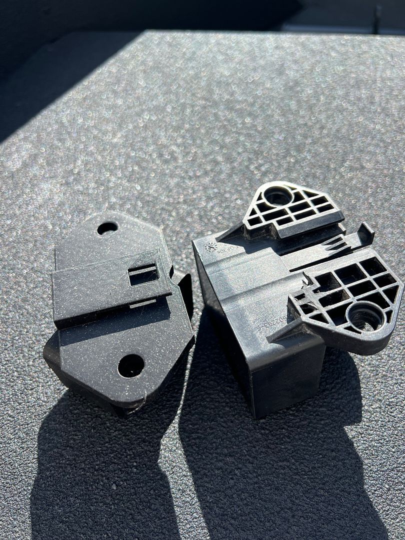
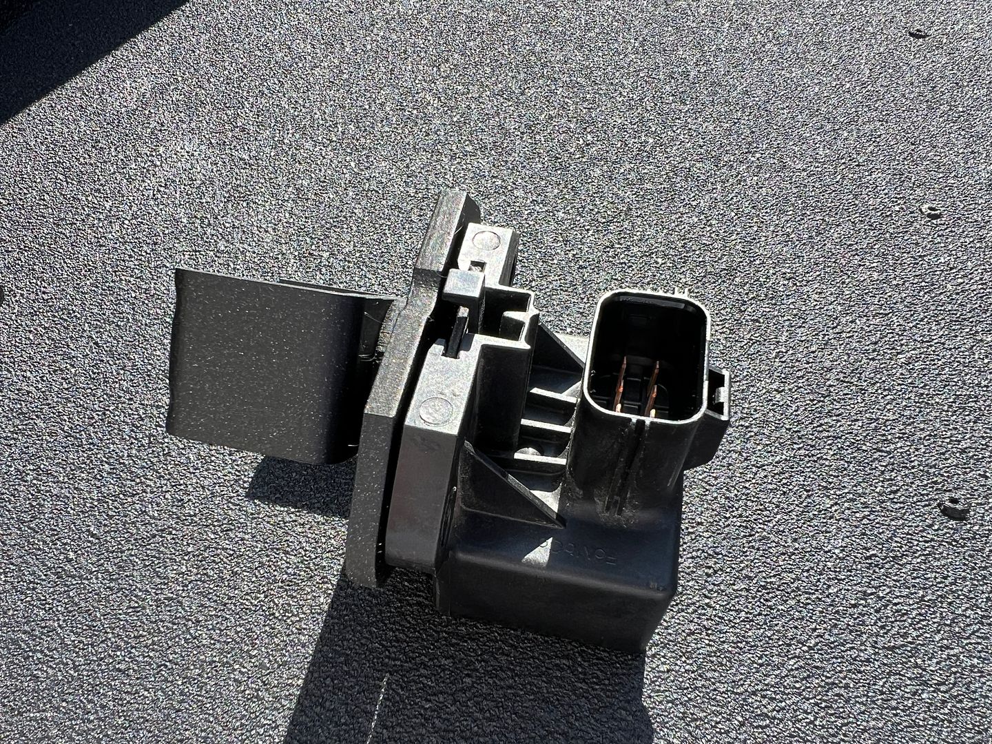
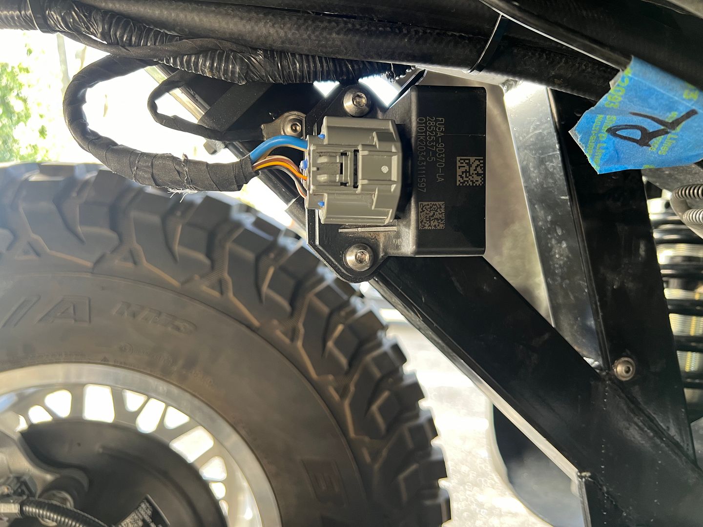
As I work my way to the back of the truck tidying up all the wires I needed to move the electronics that control the fuel pump. The kit provides a plate to mount on to the frame Then I used that plate to attach this fuel pump controller housing to the frame.
When I removed the fuel pump controller box I saw that it was made to snap into place on the F150. Probably so as the truck can be quickly put together on the assembly line. The pump controller is snapped into place then fastened with bolts.
Just for fun, I wanted to see if I could make a mount that also allowed me to snap the housing into place then bolt it. I printed the part on the left.
Thanks to 3d printing I can make a mount that snaps to the Ford part with a satisfying click.
And here it is installed. That was only a few hours work to save a few seconds haha .
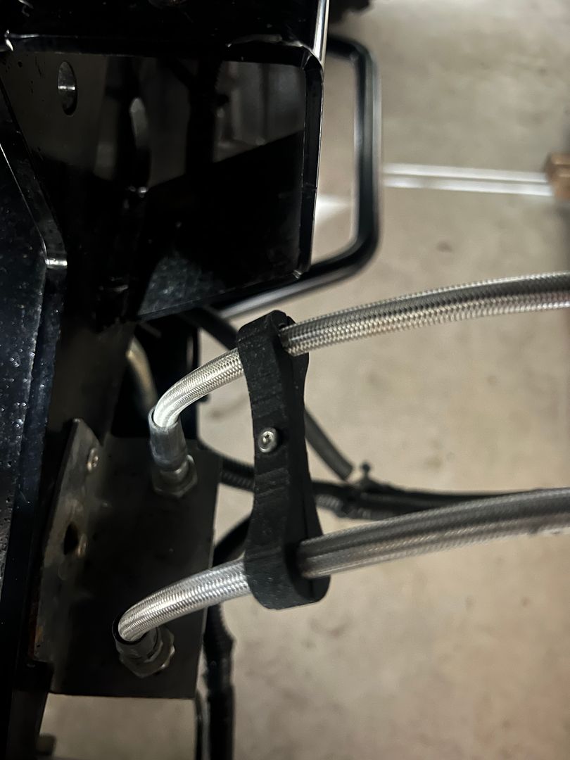
While I was at it, i made some parts to keep the stainless steel brake lines looking neat.
These work much better than the zip ties I was using.
XTF #2
build start date June 19 2023
GTM # 344
Build Start December 2010
First track day April 2013


 Thanks:
  Likes:


 Reply With Quote
_IMG_1906.png?width=1920&height=1080&fit=bounds)
_IMG_1907.png?width=1920&height=1080&fit=bounds)
_IMG_1908.png?width=1920&height=1080&fit=bounds)
_IMG_1909.png?width=1920&height=1080&fit=bounds)
_IMG_1911.png?width=1920&height=1080&fit=bounds)