Visit our community sponsor
Ok here is the result of the body work so far on the fender edges ... I think I am finished except for rolling over the lip with filler. Am I Right or Wrong?
Some waves were created by me when I took the panoramic photos of the entire fender
Front DS Fender Edge Looking to the Rear
Front DS Fender Edge Looking Forward
Rear PS Fender Edge Looking to the Rear
Rear PS Fender Edge Looking Forward
Rear DS Fender Edge Looking to the Rear
Rear DS Fender Edge Looking Forward
Feedback Please ... Thanks
Mk 4 Roadster
October 25, 2012 - Kit Arrives
April 8, 2013 - Build Starts
August 23, 2015 - Rolling Chassis/Engine & Transmission Installed
March 26, 2016 - Go Cart
carlewms,
When I trimmed my wheel well edges, I used an angle grinder with a 1/16th inch wide cutoff wheel and thought that I did a reasonable job, however, after seeing how nice yours are,I am disappointed in mine. Especially after seeing that you used an ax and three hand crosscut saws to do it.
Yeah! I never thought of using a rusty handsaw! What I can tell from the photos looks good; we could get a better perspective looking from the side with the body right side up. Unlike Mk3s and earlier I don't fill the backside (unless I happen to screw up and make a little bobble creating a wonky radius---not that I'd ever let that happen ).
Jeff
Thanks Guys,
My assistant was not available to flip the car over for these photos ... so I just decided it was easier flipping the whole world upside down ...
Driver's Side
PS Front Fender
DS Front Fender ... Passenger's Side Showing Extra "Hump" (I know it is a highly technical term) in the green circle on both of the photos. I was pretty sure I did not remove that much material from the front DS area so i will need to "adjust". Am I right?
PS Rear Fender
DS Rear Fender
As soon as I can get the body flipped right side up, I will check again.
Thanks for getting me to check it because I probably would not have caught that difference readily.
Carl
Mk 4 Roadster
October 25, 2012 - Kit Arrives
April 8, 2013 - Build Starts
August 23, 2015 - Rolling Chassis/Engine & Transmission Installed
March 26, 2016 - Go Cart
Subscribed. Need to drink V8 juice to right myself onto the correct side.
I have never filled the backside.......of a wheel lip...da Bat
Carl,
Ixnay the humps (I call 'em "hiccups" or "elbows" which are also technical terms). Straight out of the mold there are all kinds of funky wee-wahs (getting technical again ) from the front of the wheel opening around to the oil cooler scoop. I always work them over with the DA to eliminate the erratic in and outs so that it winds up making a smooth continuous curve like so:
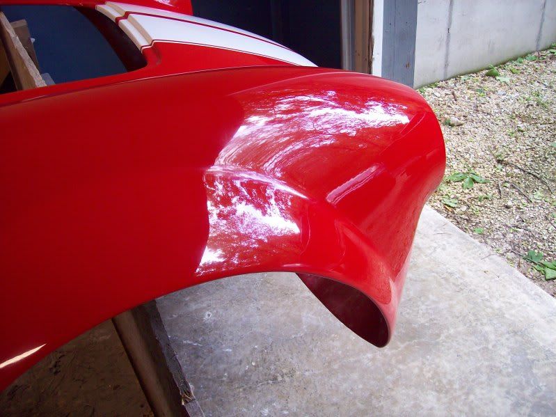
Cheers,
Jeff
Thanks everyone ...
Jeff: Thanks for the photo ... it helps understand the words for us visual types!
Carl
Mk 4 Roadster
October 25, 2012 - Kit Arrives
April 8, 2013 - Build Starts
August 23, 2015 - Rolling Chassis/Engine & Transmission Installed
March 26, 2016 - Go Cart
The SpeedHut Speedometer sent for conversion to GPS arrived yesterday so I broke it out today and did a quick bench check to see that it works.
Materials included in the conversion are:
(1) Speedometer ... the FFR one returned converted;
(1) GPS Antenna & Cable # G-SNDR-20
(1) Dash Lighting Pig Tail & Connector ... to connector to inverter; and,
(1) Power Distribution Cable ... to provide power and Gauge Dial Lighting.
To change the set up and change the settings the Gauge Programming Button is used. I previously purchased an extra one so I could permanently install one for the speedometer and the clock.
(1) Gauge Programming Cable # A-BUTTON-01
The unit uses the same digital display sized box as the non GPS version and has eight function screens:
Odometer and Trip ... Total Mileage on top and Trip Mileage on the bottom
Clock ... and Odometer
Elevation ... and Odometer
Speed ... and Odometer
Direction ... and Odometer
Peak ... Shows top speed reached since last reset
0-60 MPH Time
1/4 Mile Time
On the bench inside the house, it took about 40 seconds to acquire the satellites when connected to power. With the power supplied from un-switched power it is supposed to power up within seconds.
Mk 4 Roadster
October 25, 2012 - Kit Arrives
April 8, 2013 - Build Starts
August 23, 2015 - Rolling Chassis/Engine & Transmission Installed
March 26, 2016 - Go Cart
The number of outlets I prepared this diagram showing what I "think" i want to do or try.
Here are the notes from the drawing since they are a little hard to read ...
Installation Notes
1. Red = 2" ducting.
2. Blue = 3" ducting for Outside Air
3. F = Forward Facing Round Louver
4. D = Down Facing Round Louver
5. 2"BG = 2" Aluminum Blast Gate controlled from DS of cockpit
6. 3"BG = 3" Plastic Blast Gate controlled from Heater Fan Control Knob
Operations Notes
1. Heat: Maximize heating by closing both blast gates.
2. Defrost: Maximize defrost by opening 2"BG and close louvers.
3. Cooling: Maximize cooling by keeping HCV shut during warmest months and opening 3"BG
Any other thoughts ... I could just divert the top DS outlet to the defrost and have only one to the DS.
Thanks,
Carl
Mk 4 Roadster
October 25, 2012 - Kit Arrives
April 8, 2013 - Build Starts
August 23, 2015 - Rolling Chassis/Engine & Transmission Installed
March 26, 2016 - Go Cart
Carl, I scrolled back through your build looking for the water diverter valve you are using for the heater and didn't find it in the heater installation so I assume you haven't completed it yet. I have the Coyote and use the required four port diverter valve for the heater. That valve doesn't have very good sealing between the ports and leaks some hot water through the heater core when it is supposed to be closed. Some hot air comes from the vents when the AC and circulation fan is off. Depending on the diverter valve you use, the cooling air you expect through the heater box may not be as expected.
The broken joint you repaired in the heater core was caused by the long copper pipes soldered to the inlet/outlet tubes and will happen again if the ends at the hose connections aren't supported so no movement occurs. Even then, I suspect you will have another leak after some time. Solder joints don't handle vibrations well unless a lot of overlap is in the joints and the copper/brass in the heater core work hardens with vibration induced movements which leads to cracking. I think a piece of heater hose in the long copper tube sections will decouple the stress and prolong the life of the heater core.
Last edited by 2bking; 09-30-2016 at 08:50 AM.
King
Roadster #8127, ordered 7/12/13, received 9/11/13
http://thefactoryfiveforum.com/showt...4-Coyote-Build
King,
Thanks for the feedback ...
I got information from Vintage Air and someone who installed their servo motor controlled valve that it does fully isolate the heater. The Vintage Air Part is their "Vintage Air Replacement Heater Valve Controls 50507-VUA". If it still leaks when I try it ... I guess I wont have cooling.
The heater core was brand new and still in the plastic wrap from Vintage Air so I was a bit surprised when it leaked like a sieve.
I will implement your idea on the heater hose; right now they are only really supported by the rubber grommets as they go through the side of the enclosure.
Mk 4 Roadster
October 25, 2012 - Kit Arrives
April 8, 2013 - Build Starts
August 23, 2015 - Rolling Chassis/Engine & Transmission Installed
March 26, 2016 - Go Cart
Another modification or should I say add on ...
The fuel tank filter was ready for installation on the PS behind the wheel well by the the filler pipe. Taking inspiration from EdwardB's use of PVC, I did the same making use of some pipe I had around the garage plus some other parts from the local hardware store. After roughing the PVC up and using some filler to make it look more like metal, it was painted with 3 coats of Eastwood's Detail Grey Bare Steel Replication paint. I riveted two wire tie mounts to the outside wall of the trunk and mounted the filter with two wire ties. When I get the activated charcoal (from the pet store) I will install the scotch pad retainers and the activated charcoal.
Charcoal Fuel Vent Filter Materials
(1) 1.5" ID PVC Pipe 5 inches long
(1) 1.5" ID PVC End Cap
(1) 1.5" ID PVC Coupler
(1) 1.5" ID PVC Clean Out Plug
(1) 1.5" ID PVC Plug
(2) Hose Barbs 1/2" x 1/2" NPT
(1) Fish Tank Charcoal Filter
(2) Scotch Pad Filter Media Retention (at each end of the filter)
(1) Primer
(1) Paint, Eastwood's Detail Grey Bare Steel Replication
(1) PVC Primer & Glue
(2) 3/16th Aluminum Rivets modified to fit the cable tie mount
(2) Cable Tie Mount, Fastener Mount, 2 Way, 0.30" Maximum Tie Width, 7/8" Long, Black
(2) Plastic Wire Ties
(2) #8 Stainless Steel Clamp 7/16" - 29/32"
The top is removable so that filter media can be added or changed in the future ....
/
Just prior to installation ...
After Installation ...
We continue to have rain pouring down so I made no progress on the body yesterday ... ugh!
Mk 4 Roadster
October 25, 2012 - Kit Arrives
April 8, 2013 - Build Starts
August 23, 2015 - Rolling Chassis/Engine & Transmission Installed
March 26, 2016 - Go Cart
Ok I didn't go a shoot an elephant ...
Elephant Ears or the front wheel well liners are installed ... and made removable. Stealing the idea from EdwardB and others, instead of using rivets, 1/4-20 1/2" bolts and rivnuts were used (4 to the F-panel now and another to the body when finally installed after the body goes on).
The DS was installed as is but the PS was modified for the 3" vent duct installed belong the 3/4" frame member running along side the engine compartment. Trim will be installed on the cutout to protect the duct from chaffing on the sheet metal and the bubble seal installed on the parts alongside the body.
Driver's Side:
Passenger's Side:
Final trimming as required will be done after body is on the frame and ears reinstalled.
Mk 4 Roadster
October 25, 2012 - Kit Arrives
April 8, 2013 - Build Starts
August 23, 2015 - Rolling Chassis/Engine & Transmission Installed
March 26, 2016 - Go Cart
While out of the garage earlier in the week, most of my remaining parts for the heater came in ...
I received the 90 deg fitting to install in the engine for the heater supply line ...
The only place I have left is the location on the thermostat housing.
It would seem that the lower part of the fitting will extend all the way to the bottom of the housing or may not even permit the full engagement of the threads ... so here is my question:
Do I trim off part of the fitting? and if so how much
Carl
Mk 4 Roadster
October 25, 2012 - Kit Arrives
April 8, 2013 - Build Starts
August 23, 2015 - Rolling Chassis/Engine & Transmission Installed
March 26, 2016 - Go Cart
Trim it at the bottom of the threds....no reason for the standpipe...da Bat
While in NC some more parts for the heater arrived ... unfortunately not all were the right ones.
The High Temp Silicone 2-ply Air Duct, 3 inch diameter, 6 foot temperature resistant 3" vent duct arrived from Pegasus Racing. Although quite a bit stiffer than the Duct Hose, Very Flexible, for Dust, Polyester, 3" ID from McMaster-Carr, it was still flexible enough install easily with the SS wire ties. I actually think it looks more automotive than the old stuff not to mention much safer.
After doing a little research on the internet I cleaned up the steel wire ties for safety reasons: to secure them from coming loose and being a future cut hazard. They also look a lot neater. Basically you trim them to about 1/2" remains from the clasp, take some needle nose pliers and roll the remainder in the direction of the clasp tightening and securing the tie.
Mk 4 Roadster
October 25, 2012 - Kit Arrives
April 8, 2013 - Build Starts
August 23, 2015 - Rolling Chassis/Engine & Transmission Installed
March 26, 2016 - Go Cart
Servo Operated Heat Control Valve. With three major components to locate: The heater control valve (HCV), the controller and the dash control.
HCV: The valve is installed between the manifold (really the thermostat housing) and the heater core just behind the throttle body ... about the only spot I could find for it without major re-plumbing.
5/8" Heater Hose: The hose was routed from the HCV to the 1/4" NPT 90 deg elbow along the PS valley between the throttle body and the valve cover.
Controller: Mounted on top of the heater fan enclosure with wiring routed to power supply and the dash controls via the bulkhead connector.
Dash Control: The rheostat for the HCV (Heat Control) was located just above the Heater Fan Speed/Fresh Air Control on the dash. For now the Vintage supplied knobs are installed; later I will install more period appropriate knobs.
90 Deg 1/4" NPT Barb Fitting: As it turned out this fitting required modification to be installed on the thermostat housing. 1" of the fitting below the NPT fitting was cut off to clear the water stream in the housing. In order to install the fitting the barb end had to be cut to clear the 90 deg outlet on the thermostat housing. After cutting the barb I was able to raise the edge enough to provide a ridge to help hold the 5/8" hose.
Before:
After:
Mk 4 Roadster
October 25, 2012 - Kit Arrives
April 8, 2013 - Build Starts
August 23, 2015 - Rolling Chassis/Engine & Transmission Installed
March 26, 2016 - Go Cart
Bill,
Thanks ... yes those would look nice instead of the Vintage Air ones ... I found blanks at Holden site in UK but still looking to see if I can find a U.S. company with them like Moss for example.
Carl
Mk 4 Roadster
October 25, 2012 - Kit Arrives
April 8, 2013 - Build Starts
August 23, 2015 - Rolling Chassis/Engine & Transmission Installed
March 26, 2016 - Go Cart
Bill,
I found these on eBay but still from UK ...
LUCAS HEATER FAN DASH KNOB AC COBRA FORD GT40 NEW
http://www.ebay.com/itm/LUCAS-HEATER...VUNqAI&vxp=mtr
AUSTIN HEALEY 3000 BN4 TO BJ8 AC COBRA FORD GT40 DASH KNOB PULL17H1493 COLD AIR
http://www.ebay.co.uk/itm/291885592779
Mk 4 Roadster
October 25, 2012 - Kit Arrives
April 8, 2013 - Build Starts
August 23, 2015 - Rolling Chassis/Engine & Transmission Installed
March 26, 2016 - Go Cart
I like those style! Need one for my heater control, and one for my headlights. All my other switches are toggles.
I wonder how hard they would be to adapt to the shafts? If they used a set screw, rather than being threaded on, perhaps they could just be drilled out as needed?
Bill,
I will try to remember the thread but one of the guys on the other forum came up with a solution.
1. Purchase 1/4" brass stock from McMaster-Carr (Ultra-Machinable 360 Brass, Bar, 1/4" Hex Size #8952K23))
2. Epoxy the brass into the knob;
3. Drill out the brass to match the diameter of the switch or cable;
4. Drill and tap the knob for a small set screw; and,
5. Install the set screw to retain the knob.
I did confirm with the seller on eBay that the knobs all have the 1/4" hex opening.
Carl
Mk 4 Roadster
October 25, 2012 - Kit Arrives
April 8, 2013 - Build Starts
August 23, 2015 - Rolling Chassis/Engine & Transmission Installed
March 26, 2016 - Go Cart
The plumbing for the heater finally arrived and is installed ...
Thermostat Connection to the heater supply hose ...
From the front of the engine to the heater via the PS valley ...
Through the servo operated heater control valve (HCV) ...
The Electronic Control Unit (ECU) for the HCV is on the top of the enclosure ...
Carl
Mk 4 Roadster
October 25, 2012 - Kit Arrives
April 8, 2013 - Build Starts
August 23, 2015 - Rolling Chassis/Engine & Transmission Installed
March 26, 2016 - Go Cart
Looking good Carl!
Surely you will be done for TCC 2017, right?
FFR 7123 tilt front, Levy 5link/wilwoods/LCA's, webers.
SL-C, LS3 525, Mendeola SDR5,
Hey Carl, I know you've been through a thousand different ideas, thoughts and changes on this system, but just for discussion... are you expecting any issues with the heater tap on the cold side of the t-stat?
I found a blank one and had a local sign company label it very similar to the vintage lettering. Cost $40, though. Both knobs were attached to the original switch posts with a little epoxy as filler for the flat side of the post. Also drilled and tapped for a set screw.
Knobs.jpg
Boydster,
Yes but I am not sure it will matter that much ... I think (since I have not had the engine up to temperature yet with the heater installed) that:
Before the engine heats up to start opening the T stat there won't be much heat except perhaps by conduction from the intake manifold to the t-stat housing. There will also be flow through the bypass but I don't think that will make a significant difference since it also bypass the heater connection.
I think it will be slower without the heater in the loop before the engine gets hot enough for the T-stat opens but I am not sure if that will be a significant enough of a difference to warrant moving things around. After driving the car if it does I can look at moving the location to one on the manifold.
Perhaps someone with more practical experience can weigh in and answer in case I am thinking totally wrong.
Carl
Mk 4 Roadster
October 25, 2012 - Kit Arrives
April 8, 2013 - Build Starts
August 23, 2015 - Rolling Chassis/Engine & Transmission Installed
March 26, 2016 - Go Cart
Does the electric HCV allow you to vary the volume of water passing through the the heater, or is it simply open or closed?
The heater can act as mini-radiator, and actually lower your coolant temp's slightly, when the valve is open, and the fan is running.
My thinking is that there will be zero heat until the engine comes fully up to temp to open the t-stat. On cold days, you may never get any heat at all. With t-stat closed, There's virtually zero flow through the HVC because nothing is flowing right there on the cold side of the t-stat. I'm also concerned that the t-stat will reduce flow through the heater core vs coming out of the intake manifold and returning directly to the pump as originally designed. Even when full open, the t-stat is a choke point.
The original 5.0 design constantly circulated water through the heater core, using a system of doors to divert air. I understand the need for a HCV on these cars, but my point is that having water constantly circulating did not have any effect on the warm up times on a stocker.
By all means, try it. Please follow up and let us all know how it works... could be a Eureka! But if not, consider a fitting in the intake coolant passage boss just behind the t-stat that has a 90* elbow for the heater with an open port on top for your temp sensor / switch.
Side note: if there's too many switches / sensors / taps needed for the cooling system, I would put the electric fan temp switch in that spot right next to the t-stat. If the t-stat is rated for 180 and the switch for 195, it would work perfectly as it's not depended on when the engine is colder / t-stat closed.
The fans are all controlled by the EFI ECU and sense temperature on the intake manifold directly behind the t-stat housing.
Based on discussions on the other forum it was recommended to keep the sensor driving the EFI ECU on the intake manifold side because that side will tell the ECU as the temperature rises in the engine more directly than the T stat side (but clearly based on your experience it would not work on the downstream side of the T-stat). Interestingly when I asked Gordon Levy about where to put the heater inlet (he supplied the engine) he immediately came back with the t-stat housing.
Based on the various responses on the forum and your response here it seems like the "T" for two connections is the only viable solution whether in the the PS or DS of the intake manifold.
Thanks again for the great input ... I will give it a shot as installed right now and then post the results.
Mk 4 Roadster
October 25, 2012 - Kit Arrives
April 8, 2013 - Build Starts
August 23, 2015 - Rolling Chassis/Engine & Transmission Installed
March 26, 2016 - Go Cart
Folks,
This is not really an update on work accomplished but ...
I have had a health issue that has kept me out the garage since the 10/25 ... so no work other than planning, researching, getting parts in and trying to get the physical therapy done so that I can get out there and finish it up.
Regarding the heater inlet connection with the intake manifold ... I received the parts from Breeze while I was in hospital so that I can put the EFI Temperature Sensor and intake to the heater on the same fitting. It is Breeze part #70540 ECT Sensor Elbow Kit for 5/8" Heater Hose to CCW Water Pump without the hose.
The sensor goes on the top and the inlet to the heater on the side ...
Mk 4 Roadster
October 25, 2012 - Kit Arrives
April 8, 2013 - Build Starts
August 23, 2015 - Rolling Chassis/Engine & Transmission Installed
March 26, 2016 - Go Cart
Carl,
Wondered where you have been. Did you say hospital??
FFR 7123 tilt front, Levy 5link/wilwoods/LCA's, webers.
SL-C, LS3 525, Mendeola SDR5,
Excellent work Carl. Great attention to detail.
Yep ... I flew home from a business trip on 10/26... syncope struck me as I walked out; fell and messed up both knees ... walking with a walker now with a brace on the right knee. I also had a partially torn achilles tendon so I have a boot on the left leg.
I still have not been able to get back to work on the car ...
Mk 4 Roadster
October 25, 2012 - Kit Arrives
April 8, 2013 - Build Starts
August 23, 2015 - Rolling Chassis/Engine & Transmission Installed
March 26, 2016 - Go Cart