Very Cool Parts

Visit our community sponsor

Thanks Thanks:  5
Likes Likes:  2
Page 4 of 22 FirstFirst ... 2345614 ... LastLast
Results 121 to 160 of 872

Thread: Carl's Mk 4 Roadster Build

  1. #121
    Carl carlewms's Avatar
    Join Date
    May 2012
    Location
    Nokesville, VA
    Posts
    1,125
    Post Thanks / Like

    Tab on the Frame above the PS Tank Strap Bolt

    Is this tab used for anything? Can I remove it?

    image.jpg

    Carl
    Mk 4 Roadster
    October 25, 2012 - Kit Arrives
    April 8, 2013 - Build Starts
    August 23, 2015 - Rolling Chassis/Engine & Transmission Installed
    March 26, 2016 - Go Cart

  2. #122
    Senior Member edwardb's Avatar
    Join Date
    Feb 2011
    Location
    Lake Orion, Michigan
    Posts
    10,578
    Post Thanks / Like
    Asked the same question over on the other forum just less than a year ago. Seems it's needed for certain donor tanks. If your tank doesn't need it, cut if off and put a patch on the trunk aluminum. Looks neater and easier to carpet/finish the trunk area. That's what I did. Here's the thread, with a minor grammar diversion. http://www.ffcars.com/forums/17-fact...ting-what.html

    The patch is visible in this picture.
    Last edited by edwardb; 11-30-2013 at 04:58 PM.
    Build 1: Mk3 Roadster #5125. Sold 11/08/2014. Build 2: Mk4 Roadster #7750. Sold 04/10/2017. Build Thread
    Build 3: Mk4 Roadster 20th Anniversary #8674. Sold 09/07/2020. Build Thread and Video. Build 4: Gen 3 Type 65 Coupe #59. Gen 3 Coyote. Legal 03/04/2020. Build Thread and Video
    Build 5: 35 Hot Rod Truck #138. LS3 and 4L65E auto. Rcvd 01/05/2021. Legal 04/20/2023. Build Thread. Sold 11/9/2023.

  3. #123
    Carl carlewms's Avatar
    Join Date
    May 2012
    Location
    Nokesville, VA
    Posts
    1,125
    Post Thanks / Like
    Edward,

    Thanks for the rapid feedback. I have got the tab removed and waiting for the paint to dry.

    Carl
    Mk 4 Roadster
    October 25, 2012 - Kit Arrives
    April 8, 2013 - Build Starts
    August 23, 2015 - Rolling Chassis/Engine & Transmission Installed
    March 26, 2016 - Go Cart

  4. #124
    Carl carlewms's Avatar
    Join Date
    May 2012
    Location
    Nokesville, VA
    Posts
    1,125
    Post Thanks / Like

    Burp Tank Installation In Progress

    Saturday was spent working a little on the engine, a little on garage clean up and organization and last but not least getting more hardware for mounting components.

    I spent most of the time getting the FE Burp Tank mocked up on the engine. In my somewhat misguided quest to at least make the visible parts of the build look old school I decided to include a big block FE Burp Tank just forward of the distributor above the water pump. Not a new idea having been done by several and there is an excellent how to on now of the ffcars.com site.

    Here are some photos of the results so far ... I will be moving the alternator and installing V belt pulleys with a CW rotating water pump so all this has to come back off.


    I fabricated a mounting bracket from 1/8 in aluminum plate, drilled it out to match up with the holes on the pump casing and the burp tank bracket, bent it to get clearance from the distributor and then trimmed off the bottom to match the contour of the timing gear cover behind the water pump.


    The mounting bracket, in primer, is held in place by 2.5 in long 5/16-18 cadmium bolts which will be held on place by nut and lock washer.

    Here is the view from the DS.


    Here is the view from the PS.


    Still need to get the tank pressure tested and mock up the connections from radiator which occur after I get the engine in the car.
    Mk 4 Roadster
    October 25, 2012 - Kit Arrives
    April 8, 2013 - Build Starts
    August 23, 2015 - Rolling Chassis/Engine & Transmission Installed
    March 26, 2016 - Go Cart

  5. #125
    Carl carlewms's Avatar
    Join Date
    May 2012
    Location
    Nokesville, VA
    Posts
    1,125
    Post Thanks / Like

    Source for 427 SC Dash

    Does anyone have a source for the SC dash? I would like to replace my FFR 427 dash with one that is already cut and a little thicker than the factory supplied version. Carl
    Mk 4 Roadster
    October 25, 2012 - Kit Arrives
    April 8, 2013 - Build Starts
    August 23, 2015 - Rolling Chassis/Engine & Transmission Installed
    March 26, 2016 - Go Cart

  6. #126
    Carl carlewms's Avatar
    Join Date
    May 2012
    Location
    Nokesville, VA
    Posts
    1,125
    Post Thanks / Like

    First Trunk Sheet Metal Permanently Installded

    One of the most challenging aspects of building these cars, specially if you are doing modifications from the standard build, is sequencing the installation. In this case I needed to make sure the quick jack bolts were installed before the gas tank. That meant I had to have the sheet metal in that area installed so I could install the bolts...etc, etc, etc.

    Taking inspiration from the lessons learned by others, I installed the quick jack connections so I would avoid the issues of trying to do it with the tank installed. All parts were sourced from McMaster-Carr.

    First I sourced the same size and thread count as the bolts supplied by FFR to maintain consistency or adaptability with existing over riders or nerf bars (7/16-14). All components were treated with SharkHide prior to installation.

    (4) Bolts 1.5 in
    (8) Nuts
    (8) Washers
    (4) Coupling Nuts 1.25 in

    The following additional components will be used to attach the body and quick jacks/over riders.

    (1) All Thread (to be cut to fit)
    (8) Nuts
    (8) Washers

    The 1.5 inch bolt were installed with washers on either side of the frame with a dab of Wellwood on each component.

    I then installed the panel using 1/8 in aluminum rivets and adhesive. The nuts were then installed on the quick jack bolts followed by the coupling nut. I may need to order longer coupling nuts to get more engagement on the all thread.


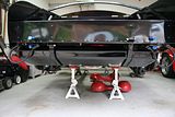
    Since I removed the tab on the passenger side of the rear gas tank support, I fabricated a small cover to fill in the hole remaining.


    Here is a photo of the completed installation.


    Carl
    Mk 4 Roadster
    October 25, 2012 - Kit Arrives
    April 8, 2013 - Build Starts
    August 23, 2015 - Rolling Chassis/Engine & Transmission Installed
    March 26, 2016 - Go Cart

  7. #127
    Carl carlewms's Avatar
    Join Date
    May 2012
    Location
    Nokesville, VA
    Posts
    1,125
    Post Thanks / Like

    Comparison between the FFR and Finish Line Over Riders

    Folks,

    In a previous post Bill asked about the difference between the FFR and the Finish Line over riders. Over the holidays I received the two I ordered from Finish Line. Here are a couple of photos. For comparison I am using the one Bill provided in a photo (which I am assuming is an FFR version) from his car:


    Here is the over rider from Finish Line which is different ...

    Back of the over rider.


    Unlike the FFR version, the attachment points are in two threaded bosses ... here are a couple of views.

    Looking into the bosses:


    Side view of the bosses:


    View of the side wall of the over rider:


    Other differences ... The FFR appears to be stamped metal (I think) while the Finish Line is chrome on brass. It would appear that the FFR version has more room for adjustment since you can get behind the attachment point whereas you cannot on the Finish Line version.

    Since I like the Finish Line versions better I will need to rethink how I will attach all to the body now.

    Carl
    Mk 4 Roadster
    October 25, 2012 - Kit Arrives
    April 8, 2013 - Build Starts
    August 23, 2015 - Rolling Chassis/Engine & Transmission Installed
    March 26, 2016 - Go Cart

  8. #128
    Senior Member
    Join Date
    Jul 2013
    Location
    Tacoma, WA
    Posts
    139
    Post Thanks / Like
    Carl, I have the Finnish Line full bumpers as well and need to find a way to make it easier. I think the front will work out OK using nuts inside on the frame but the back its harder with the fuel tank in the way. I was thinking of trying to find coupling nuts with one side reverse threaded so it would work like a coupler. Would need a reverse threaded bolt to go into the frame with a nut. Then you could place the all thread in the over rider, through the body, then thread and tighten them together with the coupler. Not sure how it would work or where to get the hardware but one idea. I'm watching to see what you come up with and how well it works. Also, are you going to use the Finnish Line rubber bushings in the rear or stay with the split tube to hold the body?
    Rod
    FFR 3749 MkII, 428PI, TKO-600, IRS, Pin-Drive, Tri-States body, Under Car Exhaust
    Rod's BB Street Cobra Build

  9. #129
    Junior Member
    Join Date
    Feb 2013
    Location
    Denver, CO
    Posts
    2
    Post Thanks / Like

    One Step Further

    I did the same and I took this one step further to make a clean trunk. I also cut off the tank strap mount and weld it back on below the aluminum panel like the DS strap mount is. This also required cutting out some of the tank strap between the loop and strap to compensate for lowering the mount. I then welded the loop back onto the strap. Now I'm able to patch the entire area creating a clean lower trunk area for carpet installation and storage .

  10. #130
    Junior Member
    Join Date
    Feb 2013
    Location
    Denver, CO
    Posts
    2
    Post Thanks / Like
    Quote Originally Posted by carlewms View Post
    Is this tab used for anything? Can I remove it?

    image.jpg

    Carl
    I did the same and I took this one step further to make a clean trunk. I also cut off the tank strap mount and weld it back on below the aluminum panel like the DS strap mount is. This also required cutting out some of the tank strap between the loop and strap to compensate for lowering the mount. I then welded the loop back onto the strap. Now I'm able to patch the entire area creating a clean lower trunk area for carpet installation and "storage"- ha ha.
    Last edited by milehighsnake; 01-08-2014 at 12:09 AM.

  11. #131
    Carl carlewms's Avatar
    Join Date
    May 2012
    Location
    Nokesville, VA
    Posts
    1,125
    Post Thanks / Like
    Mile High

    I like that idea .. I do not have any welding capability so I would have to get someone to do it for me. I sure would make for a cleaner looking trunk and an easier installation.

    Carl
    Mk 4 Roadster
    October 25, 2012 - Kit Arrives
    April 8, 2013 - Build Starts
    August 23, 2015 - Rolling Chassis/Engine & Transmission Installed
    March 26, 2016 - Go Cart

  12. #132
    Carl carlewms's Avatar
    Join Date
    May 2012
    Location
    Nokesville, VA
    Posts
    1,125
    Post Thanks / Like
    Quote Originally Posted by rlampman View Post
    Carl, I have the Finnish Line full bumpers as well and need to find a way to make it easier. I think the front will work out OK using nuts inside on the frame but the back its harder with the fuel tank in the way. I was thinking of trying to find coupling nuts with one side reverse threaded so it would work like a coupler. Would need a reverse threaded bolt to go into the frame with a nut. Then you could place the all thread in the over rider, through the body, then thread and tighten them together with the coupler. Not sure how it would work or where to get the hardware but one idea. I'm watching to see what you come up with and how well it works. Also, are you going to use the Finnish Line rubber bushings in the rear or stay with the split tube to hold the body?
    Rod
    Rod,

    The short answer on your last question is have purchased the grommets from Finish Line and plan to them instead of the split tube. I just got the rubber bushings yesterday and I will post some photos later this evening.

    I consistently use McMaster Carr for all the hardware. I will post a list of materials and part numbers later this evening so that you have those available.

    Essentially what I have done is taken a bolt and mounted from inside (front) the frame with a washer on both sides of the frame. I then put a nut on the outside (backside) of the frame to secure the bolt. Remember to do this after installing the sheet metal that goes on the vertical part of the trunk (I am not sure that is applicable to a Mk II).

    I then installed a coupler on the bolt (just after the rear nut described above). I need to check your point on the reverse thread and will let you know what I find out. When I originally designed my solution I was thinking of the FFR style over rider.

    Based on the way the threads go into the Finish Line over riders it will be important that the bolt or all thread is fully seated in the boss to avoid creating a weak point in the whole assembly.

    Carl
    Mk 4 Roadster
    October 25, 2012 - Kit Arrives
    April 8, 2013 - Build Starts
    August 23, 2015 - Rolling Chassis/Engine & Transmission Installed
    March 26, 2016 - Go Cart

  13. #133
    Carl carlewms's Avatar
    Join Date
    May 2012
    Location
    Nokesville, VA
    Posts
    1,125
    Post Thanks / Like

    Finally ... Back in the Garage Working on the Engine

    Quick Review: With the installation of an FE Burp Tank on my SB engine I needed to move the alternator out of the way, i.e. lower on the PS of the engine. The engine as built has a CCW water pump set up to with a smooth pulley to run a serpentine belt.

    This required get a CW water pump and a six grooved pulley and that is where the fun began. Now it is not like I am the first guy to do this but the forums were all confusing. Some posts said you had to change the timing gear cover while others said it did not really matter. After actually speaking with some folks that have done it ... the answer was maybe.

    Apparently if you have a timing gear cover for a Fox body car from 79 to 93 and a CW water pump from an 89-91 Crown Victoria the ports align properly and, since the impeller is reversed on the pump, the flow will go in the right direction.

    After what seemed like an eternity searching the internet I finally got all the parts sourced including the bracket which was the hardest to find (at least for me).

    The first photo shows the timing gear cover with the right and left inlets to the engine block clearly shown.


    These pumps are centrifugal pumps where the fluid is drawn to the center of the pump impeller or the eye and then exits the pump at the edge of the impeller and volute at a higher pressure thus creating the flow.

    Without taking the cover off the back of the pump you cannot really tell that the impeller on the CW pump is reversed but you can tell the discharge ports at the edge of the pump clearly align.

    First the old pump ...


    Next the new pump ...


    I had originally planned to do a more old school look of a v belt but after going through all this I will save that change for a post completion modification.

    It felt good to get back out wrenching it again.

    Carl
    Mk 4 Roadster
    October 25, 2012 - Kit Arrives
    April 8, 2013 - Build Starts
    August 23, 2015 - Rolling Chassis/Engine & Transmission Installed
    March 26, 2016 - Go Cart

  14. #134
    Senior Member Gordon Levy's Avatar
    Join Date
    Feb 2011
    Location
    Maricopa AZ
    Posts
    1,277
    Post Thanks / Like
    The easiest way to tell a reverse rotation pump vs a standard rotation pump is the pulley bolt pattern. It is a wider pattern on a reverse rotation pump. Most V belt pulleys won't fit a reverse pump and visa versa.
    99/2000 NASA PSO Champion-2005 west coast FFR challenge series Champions
    Sponsor Tony B's 2007 ST2 National Championship
    2009 NASA TTC runner up-2010 NASA TTB runner up

  15. #135
    Senior Member chopthebass's Avatar
    Join Date
    Oct 2013
    Location
    Calgary, Canada
    Posts
    941
    Post Thanks / Like
    This might sound dumb for someone planning a build, but what is a burp tank?

  16. #136
    Carl carlewms's Avatar
    Join Date
    May 2012
    Location
    Nokesville, VA
    Posts
    1,125
    Post Thanks / Like
    Gordon,

    Thanks for the tip ...

    "The easiest way to tell a reverse rotation pump vs a standard rotation pump is the pulley bolt pattern. It is a wider pattern on a reverse rotation pump. Most V belt pulleys won't fit a reverse pump and visa versa".

    Chopthebass,

    Burp tank = expansion tank. The FE has a large expansion tank near the front of the engine. With some modification, the tank can be made to work on a SB engine and it the opinion of some it gives the engine compartment a more old style or (dare I say) big block look.

    Quote Originally Posted by chopthebass View Post
    This might sound dumb for someone planning a build, but what is a burp tank?
    Mk 4 Roadster
    October 25, 2012 - Kit Arrives
    April 8, 2013 - Build Starts
    August 23, 2015 - Rolling Chassis/Engine & Transmission Installed
    March 26, 2016 - Go Cart

  17. #137
    Carl carlewms's Avatar
    Join Date
    May 2012
    Location
    Nokesville, VA
    Posts
    1,125
    Post Thanks / Like

    More on the Water Pumps

    Overnight I continued exploration of the differences between the two water pumps for the engine.

    Gordon Levy provided a point that the easiest way to tell the difference between the CCW and CW water pumps was the spacing of the mounting holes for the pulley. In the photo below you can see the difference with the holes for the CW pump on the right are spaced closer than those on the CCW pump on the left. The March 6 groove pulley came drilled for both spacings.


    The pump on the right is the CCW pump and has a slightly larger spacing. The one on the left had the new pulley mounted with the smaller pattern.

    The following is only for those that want to know how the pumps work; skip to the next two paragraphs if you don't want theory!

    In this case the colder water flows from radiator to pump inlet. This is routed to the center of the pump, specifically to the eye of the impeller. This is the lower pressure or suction side of the pump.


    The rotational energy created by the engine through the crankshaft and belt is converted to velocity energy. The shape of the volute or exit to the pump converts this velocity energy to a higher pressure before it is sent on to the engine block via the two discharge outlets. Remember that Italian guy named Bernoulli; he is responsible for describing mathematically how this all works.


    In the photo below, please remember that the direction of rotation is based on looking at the pump from the front, thus the arrows on the photos in the opposite direction.


    Besides the rotation direction difference, the only other differences that affect function are the shape of the impeller, the volutes and the previously mentioned spacing for the pulley. The volute on one side of the new pump is larger than the one on the old pump, but I am not sure that makes a whole lot of difference.

    I will get it installed this evening if all goes right.
    Mk 4 Roadster
    October 25, 2012 - Kit Arrives
    April 8, 2013 - Build Starts
    August 23, 2015 - Rolling Chassis/Engine & Transmission Installed
    March 26, 2016 - Go Cart

  18. #138
    Carl carlewms's Avatar
    Join Date
    May 2012
    Location
    Nokesville, VA
    Posts
    1,125
    Post Thanks / Like

    Alternator Mounting Bracket Kit and CW Pump Parts List

    Bracket

    The kit consists of an aluminum billet bracket, the spacers, screws and the adjustment turnbuckle to install the alternator in the lower position on the passenger side of the engine. To obtain the kit contact Aaron Price at [email protected] (He accepts PayPal) Here is photo of the kit as delivered:


    The following photo (not my car) shows the kit installed on the engine.


    Water Pump

    1. CW Water Pump: Summit (GMBH-125-1700) made by GMBH comes with paper gasket.


    2. 5.0 Liter Water Pump Pulley (MCH-2004) made by March comes with both CCW and CW mounting holes.

    Mk 4 Roadster
    October 25, 2012 - Kit Arrives
    April 8, 2013 - Build Starts
    August 23, 2015 - Rolling Chassis/Engine & Transmission Installed
    March 26, 2016 - Go Cart

  19. #139
    Senior Member edwardb's Avatar
    Join Date
    Feb 2011
    Location
    Lake Orion, Michigan
    Posts
    10,578
    Post Thanks / Like
    Quote Originally Posted by carlewms View Post
    Bracket

    The kit consists of an aluminum billet bracket, the spacers, screws and the adjustment turnbuckle to install the alternator in the lower position on the passenger side of the engine. To obtain the kit contact Aaron Price at [email protected] (He accepts PayPal) Here is photo of the kit as delivered:


    Ah, the famous Speed Doctor alternator bracket. That's the one I used on my Mk4 build as well. Really solid and the placement is just right.

    I was thinking about the ********** overriders, but now after seeing your pictures, not so sure. I'll be interested to see how they work out for you.

    Your build is looking great.
    Build 1: Mk3 Roadster #5125. Sold 11/08/2014. Build 2: Mk4 Roadster #7750. Sold 04/10/2017. Build Thread
    Build 3: Mk4 Roadster 20th Anniversary #8674. Sold 09/07/2020. Build Thread and Video. Build 4: Gen 3 Type 65 Coupe #59. Gen 3 Coyote. Legal 03/04/2020. Build Thread and Video
    Build 5: 35 Hot Rod Truck #138. LS3 and 4L65E auto. Rcvd 01/05/2021. Legal 04/20/2023. Build Thread. Sold 11/9/2023.

  20. #140
    Carl carlewms's Avatar
    Join Date
    May 2012
    Location
    Nokesville, VA
    Posts
    1,125
    Post Thanks / Like

    New Water Pump Installed and the Alternator Relocated

    The new water pump is installed and the alternator moved to the lower position on the PS side of the engine. Prior to mounting the components I treated them all with SharkHide. Aaron Price's alternator mounting bracket kit fit perfectly for a serpentine belt installation.


    I also mocked up the connection from the thermostat housing to the bottom connection of the burp tank. A 1 1/2 inch hose from the local Pep Boys and a 1 1/2 in aluminum tube from Breeze connect the outlet side of the coolant system. Still missing are the period correct hose clamps.


    After seeing it all together, I may need to lower the tank a bit to get more clearance on the hood. This will have to wait until I get the body on the chassis for now. By re fabricating the bracket I can lower the tank about. 2-3 inches of clearance from the hood.


    In addition to the possibility of lower the tank, I still have some painting, additional screws/bolts to install and to get an appropriate sized belt.

    I eventually will convert the serpentine belt system to a more period correct v belt system.

    Carl
    Mk 4 Roadster
    October 25, 2012 - Kit Arrives
    April 8, 2013 - Build Starts
    August 23, 2015 - Rolling Chassis/Engine & Transmission Installed
    March 26, 2016 - Go Cart

  21. #141
    Jazzman's Avatar
    Join Date
    Jan 2014
    Location
    Scottsdale, AZ
    Posts
    1,164
    Post Thanks / Like
    Thank you, Carl, for your very detailed thread. I am a good year and half behind you because I have just started designing my build. I truly appreciate your detailed experiences. I have now read your entire thread, and have been making notes as I go along. Your work has been very thought provoking. I look forward to reading more!!

    Jazz

  22. #142
    Carl carlewms's Avatar
    Join Date
    May 2012
    Location
    Nokesville, VA
    Posts
    1,125
    Post Thanks / Like
    Jazzman,

    Thanks for the kind words...I was just reading your latest posts on line and you are asking all the right questions and I am convinced the more planning upfront the better.

    Sincerely,

    Carl
    Last edited by carlewms; 01-12-2014 at 07:23 AM.
    Mk 4 Roadster
    October 25, 2012 - Kit Arrives
    April 8, 2013 - Build Starts
    August 23, 2015 - Rolling Chassis/Engine & Transmission Installed
    March 26, 2016 - Go Cart

  23. #143
    Carl carlewms's Avatar
    Join Date
    May 2012
    Location
    Nokesville, VA
    Posts
    1,125
    Post Thanks / Like

    Some Progress ... Sort Of

    With the super cold weather in Northern VA and other stuff getting in the way the build progress has been slower that desired.

    I did make some progress on the dashboard... after much deliberation I decided to go with the 427 SC dashboard instead of the standard one that comes with the kit. I first tried to find a vendor that sells a dash precut for the FFR without any luck but I did find plenty of information on the layout (or at least many variations of the alleged 427 SC layout).

    Here is my interpretation so far:


    Although I found a template for the glove compartment (which I understand was not really on an SC), I kinda feel like mine looks too small.

    I will also be adding a map light on the passenger side.

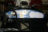
    Here is a view of the "driver's view" dash:


    I will post a larger photo showing the names on the gauges and switches but here is the general layout in words:

    From Left to Right

    Oil Temperature
    Red Light = Battery/Alternator
    Blue Light = Turn Signal
    Water Temperature
    Steering Wheel Shaft expanded and raised to accommodate RT turn signal and raised pillow block
    Green Light = Headlights
    Tachometer

    Top Row (Left to Right)

    Voltmeter
    Fuel Gauge
    Oil Pressure

    Below Voltmeter

    Switch, Fog Lamp
    Switch, Hazard Lights
    Switch, Push Start

    Below Fuel Guage

    Speedometer

    Below Oil Pressure

    Switch, Heater
    Switch, Fuel Pump
    Switch, Windshield Washer

    I still need to figure out the right spot for the light switch, but I am thinking of moving the Hazard Flasher over above the Ignition Switch and put the Light Switch in its place.

    I also need to cut the hole for the steering so that I can install the dash to check lines of sight, etc.

    For those with a FFR Mk 4, if you can provide any feedback or dimensions of how much of the dash is covered by the front cowl of the body

    Any feedback would be greatly appreciated

    Carl
    Mk 4 Roadster
    October 25, 2012 - Kit Arrives
    April 8, 2013 - Build Starts
    August 23, 2015 - Rolling Chassis/Engine & Transmission Installed
    March 26, 2016 - Go Cart

  24. #144
    Senior Member edwardb's Avatar
    Join Date
    Feb 2011
    Location
    Lake Orion, Michigan
    Posts
    10,578
    Post Thanks / Like
    Good times, huh? Went through this process a few months ago with my Mk4 build and a blank dash. You mentioned already my first thought. Make sure to set the dash in place on the chassis, put the seat in, mount the wheel, and check line of sights. Make sure you can see everything adequately. I did some tweaking with my setup at that point. Even something simple like using the thicker leather wrapped wheel vs. the standard wood wheel can make a difference.

    Regarding your actual setup, personally I would put the oil pressure gauge right in front. That with the water temp are probably your two most important gauges that indicate health of your engine, and should be watched most frequently.

    This is kind of an obvious statement, but don't forget about the size of whatever your mounting on the back while finalizing the location. The provided Delco style headlight switch takes a small hole but is big on the backside and has a large connector with pretty specific routing.

    How much of the dash is covered by the body is an often discussed subject. Obviously depends on exactly where you mount the dash on the 3/4 tube. And probably you have seen other posts (and I've personally confirmed) the curve of the top of the dash does not match the curve of the 3/4 tube, especially if you mount the dash level. Maybe you saw in my build thread, but I was concerned enough about this entire subject that I temporarily set my body on the chassis to get the exact location, overlap, etc. Overkill perhaps, but I thought it was worth the effort to be positive. Was only a couple of hours work and accomplished some other checks at the same time.
    Last edited by edwardb; 01-25-2014 at 11:30 AM.
    Build 1: Mk3 Roadster #5125. Sold 11/08/2014. Build 2: Mk4 Roadster #7750. Sold 04/10/2017. Build Thread
    Build 3: Mk4 Roadster 20th Anniversary #8674. Sold 09/07/2020. Build Thread and Video. Build 4: Gen 3 Type 65 Coupe #59. Gen 3 Coyote. Legal 03/04/2020. Build Thread and Video
    Build 5: 35 Hot Rod Truck #138. LS3 and 4L65E auto. Rcvd 01/05/2021. Legal 04/20/2023. Build Thread. Sold 11/9/2023.

  25. #145
    Carl carlewms's Avatar
    Join Date
    May 2012
    Location
    Nokesville, VA
    Posts
    1,125
    Post Thanks / Like
    All,

    I have been delinquent in my updates but also my thanks for the feedback on the dash.

    Edward: I am moving the water temperature gauge to the left position in front of the driver and the oil pressure gauge above the steering shaft.

    Right now the dash is at home...and I am on a 2 week business trip to American Samoa. Therefore I can only dream and plan on getting the mods in place when I return.

    I have a drill press, various hole saw sizes and the stepped drill bits.

    For those of you that cut your own holes in the dash, what methods and tools did you use to get all the holes of the right diameter? I am worried about screwing up the dash.

    Carl
    .
    Mk 4 Roadster
    October 25, 2012 - Kit Arrives
    April 8, 2013 - Build Starts
    August 23, 2015 - Rolling Chassis/Engine & Transmission Installed
    March 26, 2016 - Go Cart

  26. #146
    Senior Member Gordon Levy's Avatar
    Join Date
    Feb 2011
    Location
    Maricopa AZ
    Posts
    1,277
    Post Thanks / Like
    I have the correct layout. Send be a blank dash and I can have it water jetted.
    99/2000 NASA PSO Champion-2005 west coast FFR challenge series Champions
    Sponsor Tony B's 2007 ST2 National Championship
    2009 NASA TTC runner up-2010 NASA TTB runner up

  27. #147
    Carl carlewms's Avatar
    Join Date
    May 2012
    Location
    Nokesville, VA
    Posts
    1,125
    Post Thanks / Like
    Gordon,

    What would I need to do to show the relocated steering shaft for the RT turn signal? I raised the pillow block so I would need to adjust for that change.

    Thanks,

    Carl
    Mk 4 Roadster
    October 25, 2012 - Kit Arrives
    April 8, 2013 - Build Starts
    August 23, 2015 - Rolling Chassis/Engine & Transmission Installed
    March 26, 2016 - Go Cart

  28. #148
    Senior Member edwardb's Avatar
    Join Date
    Feb 2011
    Location
    Lake Orion, Michigan
    Posts
    10,578
    Post Thanks / Like
    Quote Originally Posted by carlewms View Post
    For those of you that cut your own holes in the dash, what methods and tools did you use to get all the holes of the right diameter? I am worried about screwing up the dash.

    Carl.
    You want the holes in the dash to be pretty precise, meaning the diameter of the gauges plus the thickness of the vinyl so you can pull it through the holes and bond on the back side. I wanted my gauges to be slightly snug in the opening. There may or may not be hole saws for these exact dimensions. Doesn't matter for me though because I don't have any metal cutting hole saws, and didn't want to buy them just for this. I used a variety of methods. For the larger holes, I cut them out with a sabre saw with a fine tooth metal blade. For the smaller holes, where the sabre saw blade didn't like the small turns, I free-handed with a zip bit in a Dremel tool. Some of the smaller switch holes I could use a step drill. In all cases, I rough cut to the edge of the desired outline, and then smoothed and got the final size with drum sanders in my drill press. Don't over think all of this. The aluminum really is easy to work with, and cuts and sands pretty quickly. I doubled my dash, so was doing this on .080 vs. .040, and still pretty easy.

    The blank dash does come with the steering column hole cut. (Of course you know that.) Even though I didn't change the location, I still didn't want the hole that big because it would show, like it does on my Mk3. So I made a filler and have only the smaller hole required. You could do the same.

    Before:


    After:
    Last edited by edwardb; 02-03-2014 at 06:45 AM.
    Build 1: Mk3 Roadster #5125. Sold 11/08/2014. Build 2: Mk4 Roadster #7750. Sold 04/10/2017. Build Thread
    Build 3: Mk4 Roadster 20th Anniversary #8674. Sold 09/07/2020. Build Thread and Video. Build 4: Gen 3 Type 65 Coupe #59. Gen 3 Coyote. Legal 03/04/2020. Build Thread and Video
    Build 5: 35 Hot Rod Truck #138. LS3 and 4L65E auto. Rcvd 01/05/2021. Legal 04/20/2023. Build Thread. Sold 11/9/2023.

  29. #149
    Carl carlewms's Avatar
    Join Date
    May 2012
    Location
    Nokesville, VA
    Posts
    1,125
    Post Thanks / Like

    Comparison of the New Big and Tall to the Original Leather Seats

    Folks,

    Today the my new Big and Tall leather seats arrived from FFR. I will be sending back my original leather seats for a credit but while they both are here I did a comparison of the two.


    The two versions appear to use the same frame. The extra width of the big and tall is achieved in how the foam is cut. The main difference between the two is the thickness


    The thickness of the foam padding is visible in this view of the seat backs.

    The following two photos show the differences in the seats:

    The original seat:


    The big and tall seat is deeper and wider than the original one ...


    The most noticeable difference is the thickness of the seat bottom ...

    The original seat bottom:


    The big and tall seat bottom is about 1 in thinner that the original and feels like it might be made with a stiffer foam ...


    I will post some photos of the two seats in the car later today.

    Carl
    Mk 4 Roadster
    October 25, 2012 - Kit Arrives
    April 8, 2013 - Build Starts
    August 23, 2015 - Rolling Chassis/Engine & Transmission Installed
    March 26, 2016 - Go Cart

  30. #150
    Senior Member
    Join Date
    Feb 2011
    Location
    Myrtle Beach, SC
    Posts
    2,108
    Post Thanks / Like
    Quote Originally Posted by Gordon Levy View Post
    I have the correct layout. Send be a blank dash and I can have it water jetted.
    Carl-

    That sounds like a pretty good option. I was curious also if you were able to put your measurements into a cad file. I bet that would make the process even easier. In other words, after you figure out your final layouts, translate them into a cad file and then have your dash done with a water jet.

    Thanks also for the level of detail in your posts. I have enjoyed following along.

    Regards,

    Steve

  31. #151
    Carl carlewms's Avatar
    Join Date
    May 2012
    Location
    Nokesville, VA
    Posts
    1,125
    Post Thanks / Like
    Steve,

    Let me see if I can do that ... I think one of the challenges is always going to be the distance from the body cowl to the top of the dash and how that seems to vary car to car.

    I think if I can get the dash layout into a medium which can be printed on a long sheet of paper with the standard positions then a builder could use it to adjust for the height differences and then adjust the cad file origination point to make the layout custom fit to their particular car.

    Carl
    Mk 4 Roadster
    October 25, 2012 - Kit Arrives
    April 8, 2013 - Build Starts
    August 23, 2015 - Rolling Chassis/Engine & Transmission Installed
    March 26, 2016 - Go Cart

  32. #152
    Carl carlewms's Avatar
    Join Date
    May 2012
    Location
    Nokesville, VA
    Posts
    1,125
    Post Thanks / Like

    More Comparisons between the Original and the Big & Tall FFR Leather Seats

    Folks,

    I got a chance to get both seats out in the garage this afternoon and took some additional measurements for your consideration.

    Here is a comparison of the two seat pads in reference to the x frames on the side of the Mk 4 FFR roadster:

    The first is the original seat.


    The second is the new Big & Tall seat.


    As you can see the seat pad is much lower on the newer seat. When I sat down in the car with the new seat there does seem to be less support for your calves than on the original seat ... but there is more room under the steering wheel.

    Speaking of steering wheels mine is slightly higher by about 1 1/4 inches (best guess) because I mounted a 1/2 in aluminum block under the pillow block to give me a little more room.

    The next two photos show the space gained (on an uncompressed seat) for my particular build. First the original seat:


    The new Big & Tall seat:


    There is definitely more room with the new seat and, unless I get on a huge weight loss plan, they are the most viable option considering I had already purchased the $800 leather seats from FFR.

    Lessons Learned if you want more room:

    1. Before you buy try out the Kirkey Lowback Vintage Seats;
    2. Before you buy try out the FFR Big & Tall Seats;
    3. If you are trying them out in someone else's car make sure that the setup of the steering wheel and any seat slides are taken into consideration;
    4. If you really want customized seats, buy the less expensive vinyl version and then take it to a local upholstery shop to get it custom fit your needs and then covered in leather if you like;
    5. The FFR Big & Tall seats sacrifice calf support for more room under the steering wheel. I once I get to the mounting stage, I may raise the front in slightly to increase the support a bit; and,
    6. For me although I like the look of the Kirkey Lowbak Vintage Seat the side aluminum or bolsters would have made getting in and out of the car more difficult than the FFR Big & Tall seat.

    Carl
    Mk 4 Roadster
    October 25, 2012 - Kit Arrives
    April 8, 2013 - Build Starts
    August 23, 2015 - Rolling Chassis/Engine & Transmission Installed
    March 26, 2016 - Go Cart

  33. #153
    Jazzman's Avatar
    Join Date
    Jan 2014
    Location
    Scottsdale, AZ
    Posts
    1,164
    Post Thanks / Like
    After reading your travails with seats, I wonder if FFR has a "big and short" seat: wide like the big and tall, but with the thickness of the standard seat pad for those of us that are somewhat "vertically challenged"!! Thanks for the detailed analysis.

  34. #154
    Carl carlewms's Avatar
    Join Date
    May 2012
    Location
    Nokesville, VA
    Posts
    1,125
    Post Thanks / Like

    Mocking Up the Dash ...

    As part of the drawn out effort to make sure that I had my dash exactly like I want it, I finally got the hole for the steering wheel shaft cut so that I could mount the dash on the car taking account of the 1/2 inch aluminum block i installed below the pillow block and the RT turn signal.

    After getting the dash on and level, I tried to install the RT turn signal but the inside diameter of the Delrin-like bushing inside the turn signal is slightly smaller than the diameter of the shaft. This prevented me from mounting the turn signal so I just put the steering wheel on without it. Even the steering wheel is sitting about 1/2 in proud of the top of the steering shaft but the view will be improved when it is fully seated.

    With the new Big & Tall seat in place, I then took the following photos placing the lens of the iPad in line with my eyes so I could record the view as I would see it so I could then I could study the views without constantly getting in and out of the car.

    Here are the results.The first view is looking down at the steering wheel:


    Here is one looking slightly to the right:


    I am a bit concerned about the Oil Pressure gauge being obscured by the cowl of the body so I may lower it a little, but otherwise I have a pretty good view and wills start the hole drilling process over the next few days.

    I am going to use my drill press for all the holes perhaps even the small ones just to make sure I get a good clean cut.

    Carl
    Mk 4 Roadster
    October 25, 2012 - Kit Arrives
    April 8, 2013 - Build Starts
    August 23, 2015 - Rolling Chassis/Engine & Transmission Installed
    March 26, 2016 - Go Cart

  35. #155
    Carl carlewms's Avatar
    Join Date
    May 2012
    Location
    Nokesville, VA
    Posts
    1,125
    Post Thanks / Like

    The SC Dash is Starting to Take Shape - Part One

    Laying out the SC dash has been one of the most mentally challenging things for me to do. After all one mistake on a cut meant restarting on another piece of sheet metal. So it was time to take the plunge... After what seemed forever planning it, I finally had all the tools needed to cut the holes.

    Since I had the original FFR dash I measured the inside diameter of holes for the gauges using my dial micrometer. I took several measurements to come to the 2 1/8th inches diameter for the auxiliary gauges and 4 1/8th inches for the speedometer and tachometer.

    I tested the system by installing the cutting bit on my drill press and running it on some sample sheet metal backed by 2 x 4.


    First I secured the sheet metal and wood 2X4 to the drill press table using two clamps. The drill press was set up to run at a slow speed. I drilled the hole with fairly light pressure on the driving the drill through the piece.


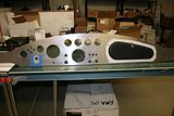
    The results are a very nice clean hole in the aluminum with just a little deburring to do to clean up the hole.


    After making sure the set up worked...

    1. Using the dial micrometer, I measured the diameter of the main and auxiliary gauge holes in the FFR supplied dash;

    2. I transferred the measurements to the cutting tool using the steel rule;


    3. I made a practice cut in the 2x4 and the checked the outside diameter with the micrometer to confirm that the cutter was set up properly;


    4. Using a 2x4 piece of soft pine was used behind the dash material, I set up the drill press to cut the hole;

    5. Taking a punch, I made sure there was significant indentation to keep the drill bit from wandering;

    6. I clamped down the entire rig after aligning the bit with the indentation; and,

    7. Here are the results after cleaning off with a foxtail.


    Carl
    Mk 4 Roadster
    October 25, 2012 - Kit Arrives
    April 8, 2013 - Build Starts
    August 23, 2015 - Rolling Chassis/Engine & Transmission Installed
    March 26, 2016 - Go Cart

  36. #156
    Carl carlewms's Avatar
    Join Date
    May 2012
    Location
    Nokesville, VA
    Posts
    1,125
    Post Thanks / Like

    The SC Dash is Starting to Take Shape - Part Two

    After installing the gauges in the new panel, I started looking at the switches. I realized quickly that I had not really done all my homework and needed to study the switches required again based on function, appearance, compare to what is on hand, and make some changes.

    I found I could use these switches:

    Switch, Ignition, Lucas, measured diameter 18.7 mm is installed
    Switch, Headlamp Flasher will be wired into the button on the RT Turn Signal
    Switch, Wipers, measured diameter 14.1 mm to be installed.

    So back to the internet and the wallet...

    I ordered the FFR version of the combination light and panel dimmer switch. It puts all the light related functions in one switch. I will get a different knob for the switch to maintain originality (http://www.factoryfiveparts.com/chassis-wiring-harness/).

    Indicator Lights. The supplied lights were ok but the blue light was very weak and looked more purple than blue ... At least to me. The LEDs will be more reliable. Here is what the FFR versions look like energized:


    I ordered LED versions of the following lights from Cobra Restorers

    Light, Alternator, Red
    Light, Turn Signal Green
    Light, High Beams, Blue

    The bezels that came with the FFR supplied 2 position switches did not match up with the bezels from the other switches or, from what I can see, the originals:


    The buttons that came with the kit has a black plastic bezel.


    I ordered the following from Finish Line:

    Switch, Start Button
    Switch, Horn Button


    Switch, Washer Fluid, Momentary, 2 Position
    Switch, Fuel Pump, 2 Position
    Switch, Fog Lamps, 2 Position
    Switch, Hazard Flashing, 2 Position

    As far as process is concerned, I prepared and drilled the holes with the Step bit as follows:

    1. Using the dial micrometer, I measured the diameter of the switch threaded shank taking care not to measure at the flats found on some of the switches;


    2. Taking these measurements, I selected the closest step on the step drill to use to drill the hole;


    3. A 2x4 soft pine block under the area to be drilled;
    4. Taking a punch, I made sure there was significant indentation to keep the drill bit from wandering;
    5. Using a variable speed drill, I drilled down to the step BELOW the one I selected in Step 2 above; and,
    6. I cleaned off the wood and metal shavings.

    Here is the result:


    Carl
    Last edited by carlewms; 03-01-2014 at 07:02 PM.
    Mk 4 Roadster
    October 25, 2012 - Kit Arrives
    April 8, 2013 - Build Starts
    August 23, 2015 - Rolling Chassis/Engine & Transmission Installed
    March 26, 2016 - Go Cart

  37. #157
    Carl carlewms's Avatar
    Join Date
    May 2012
    Location
    Nokesville, VA
    Posts
    1,125
    Post Thanks / Like

    More Dash Photos ...

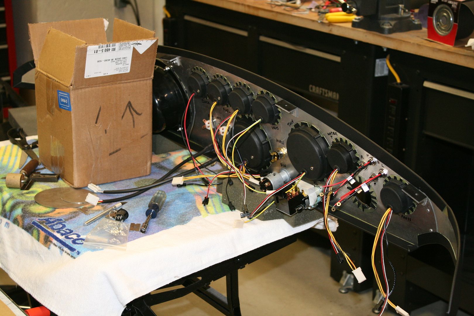
    From the driver's point of view ...


    Behind ... or is it in from to the dash ...


    From the PS of the vehicle...


    The rest awaits arrival of the new switches and a decision on the glove box ...

    Carl
    Mk 4 Roadster
    October 25, 2012 - Kit Arrives
    April 8, 2013 - Build Starts
    August 23, 2015 - Rolling Chassis/Engine & Transmission Installed
    March 26, 2016 - Go Cart

  38. #158
    Senior Member edwardb's Avatar
    Join Date
    Feb 2011
    Location
    Lake Orion, Michigan
    Posts
    10,578
    Post Thanks / Like
    Looks great. Certainly lots of precision and care (which I like...). I used that same Lucas switch on the horn. It's a nice piece (for Lucas). I also switched to LED indicator lights because the FFR one's are a little dim on some colors. Plus I didn't want to have to change incandescent. LED's should last indefinitely.

    Just one question. Do your holes sizes allow space to pull the vinyl through the holes and glue on the back, e.g. in pie shaped pieces? I've done both my builds this way, and I think is pretty common. Prevents the vinyl from pulling away which would really not be nice. I used that process wherever I could. You can see the slices on the back of my dash.

    Last edited by edwardb; 03-01-2014 at 09:02 PM.
    Build 1: Mk3 Roadster #5125. Sold 11/08/2014. Build 2: Mk4 Roadster #7750. Sold 04/10/2017. Build Thread
    Build 3: Mk4 Roadster 20th Anniversary #8674. Sold 09/07/2020. Build Thread and Video. Build 4: Gen 3 Type 65 Coupe #59. Gen 3 Coyote. Legal 03/04/2020. Build Thread and Video
    Build 5: 35 Hot Rod Truck #138. LS3 and 4L65E auto. Rcvd 01/05/2021. Legal 04/20/2023. Build Thread. Sold 11/9/2023.

  39. #159
    Carl carlewms's Avatar
    Join Date
    May 2012
    Location
    Nokesville, VA
    Posts
    1,125
    Post Thanks / Like
    Edward,

    I used the holes off the dash that came with the kit to make sure I had enough room for the vinyl. When I mocked up the instruments, the fit seems to allow room for the vinyl.

    I will check to see in the morning.

    Thanks,

    Carl
    Mk 4 Roadster
    October 25, 2012 - Kit Arrives
    April 8, 2013 - Build Starts
    August 23, 2015 - Rolling Chassis/Engine & Transmission Installed
    March 26, 2016 - Go Cart

  40. #160
    Out Drivin' Gumball's Avatar
    Join Date
    Feb 2011
    Location
    Blackberry Township, IL
    Posts
    2,653
    Post Thanks / Like
    Carl,

    Please keep us posted on whether you locate some original appearing chromed switch bezels - I've been looking for a couple and had no luck with the two sources I found in Europe. The ones I'm looking for are the ********** one you picture above and I need a few in various sizes.
    Later,
    Chris

    "There are no more monsters to fear, and so, we have to build our own."
    Mk3.1 #7074

Page 4 of 22 FirstFirst ... 2345614 ... LastLast

Posting Permissions

  • You may not post new threads
  • You may not post replies
  • You may not post attachments
  • You may not edit your posts
  •  

Breeze

Visit our community sponsor