I had so much fun chronicling my bodywork that I thought I'd start a similar thread for the process of wiring my Mk3.1. Like bodywork, I didn't know a thing about this subject before digging in earnestly about a week ago. I've planned my wiring for quite some time and everything that I've purchased was with an eye towards the end goal of using as much reproduction OEM Ford parts (sourced from the '65 - '66 Mustang parts bin) in conjunction with a Ron Francis harness that came with the kit.
Since my engine (carb'd 347 that started life in a '94 SVT Mustang) is old-school, and since I have experience with the first generation Mustang, I decided to use as much "plug-and-play" electric parts as possible. In addition to the Ron Francis harness, I'm using the following (reproduction Mustang wiring harnesses were sourced through a restoration place):
- 60 amp Ford 1G alternator
- Ford external voltage regulator
- Ford starter solenoid
- Pertronix Flamethrower coil with the top painted yellow like the original Ford part and with a Ford decal
- Original Ford dual point (small cap) distributor with Pertronix ignition module
- Group 57 battery in Breeze engine compartment tray (added fake fill caps and "Lucas" decals for period correct appearance
- '65 Mustang "headlight feed" wiring harness (because this is the harness that has the alternator / voltage regulator wiring)
- '65 Mustang alternator feed wiring harness
- '65 Mustang "engine gauge feed" wiring harness
- '65-'66 Mustang ignition switch with plug-in harness pigtail
- Smiths gauges (mostly mechanical)
- Various Mustang, MG, Healey, and Triumph switches, pumps, lamps, and accessories that I'll highlight as I go along hooking them all up (and hopefully getting them to work without burning my car to the ground).
My goal is to combine these harnesses and, once all the cutting and splicing is done, to wrap everything in cloth friction tape for that old-school look.
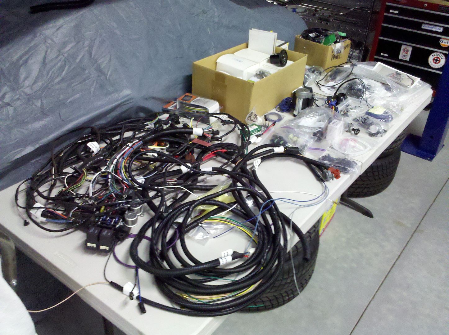
Here's what I started with:
For a guy who knows squat about electrics other than plugging new harnesses in place as I've done during past restorations, this was a very daunting pile of stuff. But, doing the bodywork myself gave me the confidence to tackle this and, like every part of this project, it's not too bad if you approach it one little project at a time. So, instead of looking at the wiring as one big step, I instead decided to deal with it in small individual projects.
Early in the build, when I made the decision to go with this sort of layout for a period-correct look, I decided to place everything in the engine compartment in a layout similar to the '65-'66 Mustang. Although not correct in comparison to the original cars, this would allow me to utilize the reproduction Mustang wiring harnesses with very little, if any, major surgery. To that end, the alternator is low on the engine to the passenger side, the coil is at the top to the driver's side, the voltage regulator is on the driver's "F" panel, and the starter solenoid is on the passenger's "F" panel. A test fit of the "headlight feed" wiring harness showed that my placement is just about right, with no need to shorten the wiring between the alternator and the voltage regulator, while leaving me enough to tuck the harness underneath the Breeze radiator top - to - body aluminum panel for a clean look.
Beyond that, I hadn't done much regarding electrics. Rather, I've spent all my time on mechanicals and bodywork. Once the engine was done and the Pertronix was in the distributor, the coil in place, and spark plug wires hooked up, I just hotwired it to get it running, both for first start and for a bunch of go-kart runs. To do that, I simply used a trigger switch jumping from the battery terminal on the starter solenoid to the "S" terminal (small connector on the left front of the solenoid) and a toggle switch wired between the positive terminal on the battery to the positive terminal on the coil. That allowed me to get about 4 - 5 hours of run time on the engine and even drive it around quite a bit! So, that mobility made me lazy and helped me to avoid any further wiring work.
As many of you will recognize, I was doing as many little projects as I could to avoid starting wiring, but I just plain ran out of other things to do and finally had to dig into this part of the project. I guess if I were using just the Ron Francis harness, I wouldn't have been so concerned, but I had no idea how, where, or why I should connect the Ron Francis harness with the reproduction stuff (or what parts of those harnesses were not needed). For the past few weeks, I've been spending all my shop time reading through wiring books - the Ron Francis manual that comes with the kit, Chilton's and Haynes' manuals, the factory assembly line electrical manual from Ford for the Falcon and first generation Mustang, a Painless Wiring instruction book, and lots of schematics and explanations found on this forum and elsewhere on the 'net. It seemed like too much at first, but eventually it all started making sense and I had no choice but to dig in.
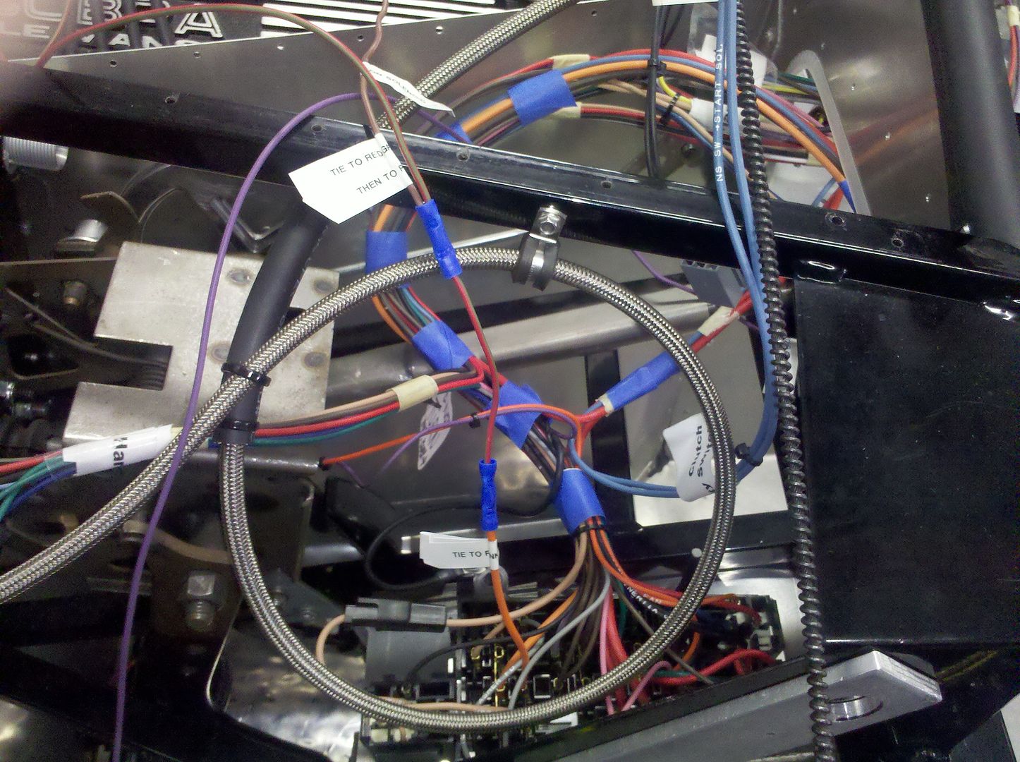
Before I began, I picked up a good multi-meter. This has proven invaluable in the process of tracing wires in the harnesses. You don't have to spend a ton of money to get a decent one, but you definitely need to have one if you want to do this right. I started by removing the black plastic split-loom cover on the Ron Francis harness. This allowed me to see where each of the wires were routed and made the whole thing much more flexible. Another thing I decided at the outset was that I wasn't going to worry about making it pretty at first... I just wanted to make everything work. This means lots of wires draped everywhere and TEMPORARY crimped connections. All of this will be cleaned up, properly soldered, wrapped, and secured before I install the body.
Here's the Ron Francis main harness temporarily set in place with the split-loom gone:
I started with what I thought was simple - deciding what parts of the '65 Mustang reproduction harnesses were needed. The "headlight feed" harness connects to the main Mustang harness at the firewall and has two distinct parts - one that feeds the headlights, parking/turn signals, and horns and another that runs between the voltage regulator and a three-pronged connector for the alternator feed harness. By stripping off the covering, I found that only two wires ran the full length from the firewall connector to the voltage regulator / alternator branch, so I cut those two and separated that circuit from the one for the lights and horns... one harness down. I'll be using what Ron Francis calls the "Front Harness" to power the headlights, front turn signals, horn, and cooling fan, so all the reproduction Ford stuff for those was sent to the surplus pile. The alternator feed harness then simply plugs into what I now call the "voltage regulator feed" harness. I pulled the alternator off the engine so that I could get a better shot at installing the harness on the back and everything fell into place.
The black/red wires connect to the ground terminal on the alternator and to the main engine block ground. The white wire connects to the field terminal on the alternator and the yellow/black wire connects to the battery terminal on the alternator. The other end of this harness has a three-pronged plug that simply plugs into the voltage regulator feed harness. Success for the first step - although not yet operational...
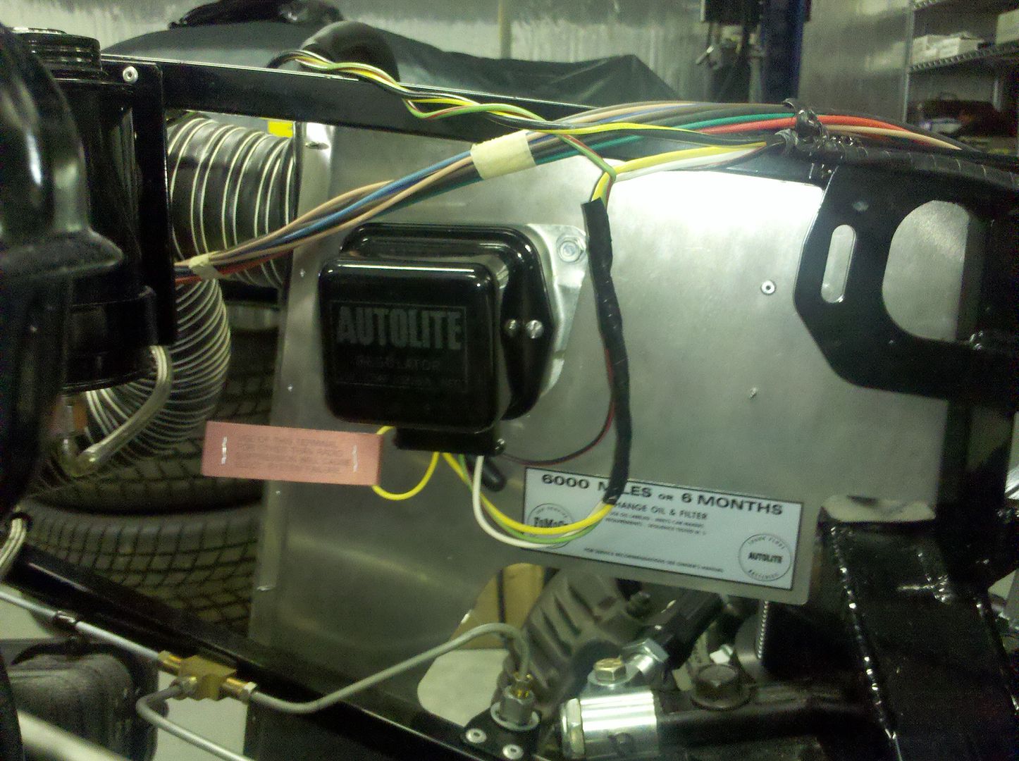
I then connected the flat three-blade plug at the other end of the voltage regulator feed harness to the voltage regulator. The white from the field terminal on the alternator goes to the "F" terminal on the voltage regulator, the black/red goes to ground at the voltage regulator mounting screw, and the yellow/black bypasses the voltage regulator and runs back towards the instrument panel (not hooked up for now - more details to come on this). There are also a couple other wires coming out of the voltage regulator - a solid yellow with a fusible link that goes to the battery terminal on the starter solenoid and a green with red stripe wire that will eventually go to the accessory post on the starter switch (also more to come on this).
Part 2 of first steps below:
- Home
- Latest Posts!
- Forums
- Blogs
- Vendors
- Forms
-
Links

- Welcomes and Introductions
- Roadster
- Type 65 Coupe
- 33 Hot Rod
- GTM Supercar
- 818
- Challenge Series
- 289 USRCC
- Coyote R&D
- Ask a Factory Five Tech
- Tech Updates
- General Discussions
- Off Topic Discussions
- Eastern Region
- Central Region
- Mountain Region
- Pacific Region
- Canadian Discussions
- Want to buy
- For Sale
- Pay it forward
-
Gallery

- Wiki-Build-Tech


 Thanks:
  Likes:


 Reply With Quote