Boig Motorsports

Visit our community sponsor

Thanks Thanks:  0
Likes Likes:  0
Results 1 to 27 of 27

Thread: Dash Indicator lights and other wiring problems

  1. #1
    Senior Member TomH33's Avatar
    Join Date
    Nov 2016
    Location
    Parker,CO
    Posts
    108
    Post Thanks / Like

    Dash Indicator lights and other wiring problems

    Hi

    Has anyone run into a problem with indicator lights. I just attached my dash temporarily so I can Go Kart the car. The gauges all worked fine, lights too. Problem is both directional Led indicators lights are on at the connection of the battery and don’t go off unless I turn the directional on. If I use a volt meter at the end of the wire marked right turn indicator light blue (with the battery connected) is always hot. Same with the Green wire marked Left dash indicator light, also hot. My feeling are they should only be hot when turned on. From here the wires disappear into the monster of a wiring harness never to be seen again. On pg 29 of the “Chassis Wiring Harness” is the configuration I used.

    Also the flasher switch. Are the flashers on when pushed in or out. The flashers work when out and off when in, the way I am wired now.

    Question 2 Does the temp sender at the bottom of the radiator produce enough voltage to trip the relay. My fans don’t come on even at 200 degrees unless I use a switch that grounds the relay. Temp is good at 180 when the fans are on.

    Any help would be appreciated.

    Thanks TomH33

  2. #2

    Moderator
    RoadRacer's Avatar
    Join Date
    Oct 2011
    Location
    Manor, TX
    Posts
    2,334
    Post Thanks / Like
    Quote Originally Posted by TomH33 View Post
    Question 2 Does the temp sender at the bottom of the radiator produce enough voltage to trip the relay. My fans don’t come on even at 200 degrees unless I use a switch that grounds the relay. Temp is good at 180 when the fans are on.

    Thanks TomH33
    Can't help with the lighting, but I moved my sender to bottom of radiator and it works great with the relay (switch and relay are stock) - but I did check my radiator and it grounds out perfectly to chassis and engine - i.e. no measurable resistance. My fan kicks on/off perfectly. Did you mount using rubber or anything?
    James

    FFR33 #997 (Gen1 chassis, Gen2 body), license plate DRIVE IT says it all! build thread
    My build: 350SBC, TKO600, hardtop, no fenders/hood, 32 grill, 3 link, sway bars, 355/30r19
    Previous cars: GTD40, Cobra, tubeframe 55 Chevy, 66 Nova, 56 F100

  3. #3
    Senior Member edwardb's Avatar
    Join Date
    Feb 2011
    Location
    Lake Orion, Michigan
    Posts
    10,781
    Post Thanks / Like
    Something isn't wired right. (Yea, I know, you didn't need me to tell you that... ) You don't mention whether the turn signals themselves are working properly. Are they? If the hazard switch isn't wired exactly right, including being a double pole switch exactly as shown in the schematic, it can backfeed into the turn signal circuit. To start, I'd recommend disconnecting all the wires from the hazard switch and see if it makes a difference, e.g. indicators and turn signals operate correctly.

    For the cooling fan, that sensor doesn't produce any voltage. It simply closes at the rated temperature, completing the ground for the relay which in turn completes the power circuit for the cooling fan. Easy enough to test. To start, I'd recommend removing the wire from the sensor and touch to a solid chassis ground. The cooling fan should run. If it does, something is wrong with the sensor or it's not getting a solid ground. If the fan doesn't run, likely something else is wrong.
    Build 1: Mk3 Roadster #5125. Sold 11/08/2014. Build 2: Mk4 Roadster #7750. Sold 04/10/2017. Build Thread
    Build 3: Mk4 Roadster 20th Anniversary #8674. Sold 09/07/2020. Build Thread and Video. Build 4: Gen 3 Type 65 Coupe #59. Gen 3 Coyote. Legal 03/04/2020. Build Thread and Video
    Build 5: 35 Hot Rod Truck #138. LS3 and 4L65E auto. Rcvd 01/05/2021. Legal 04/20/2023. Build Thread. Sold 11/9/2023.

  4. #4
    Senior Member
    Join Date
    May 2016
    Location
    North of sacramento Ca.
    Posts
    866
    Post Thanks / Like
    It has been some time but it has to do with the two purple wires or grounding. What i did is a bit different than was what FFR did, so post 182 in build.

  5. #5
    Senior Member TomH33's Avatar
    Join Date
    Nov 2016
    Location
    Parker,CO
    Posts
    108
    Post Thanks / Like
    Thanks for the help. I changed the wiring for the Fan relay. I used the sender as a ground to the relay and this should fix that problem. Still working on the turn signals.

    Are the flasher supposed to work with the button in or out?

    Thanks again

  6. #6
    Junior Member
    Join Date
    Aug 2012
    Location
    Pensacola, FL
    Posts
    14
    Post Thanks / Like
    Mine works with the button in
    and tilted back to hold it in the position.
    Last edited by captain; 06-06-2018 at 10:24 AM.

  7. #7
    Senior Member TomH33's Avatar
    Join Date
    Nov 2016
    Location
    Parker,CO
    Posts
    108
    Post Thanks / Like
    Hi Again

    Been working all day on the turn signals. I disconnected all indicator light wires Lt blue Right, Green Left, hi beam brown and pink for flasher led. According to the wiring diagram, the steering column should have the right switches for both flashers and turn signals built in. All should work, they are all factory connections I have not touched. For some strange reason no turn signals or flashers. I checked the ends of the indicator wires that are no longer in use and got a constant 12V on both blue and green and pink wires, the brown was dead. This was with the turn signals off and the flashers off. I have no Idea why they are hot, and were to look now.

  8. #8

    Moderator
    RoadRacer's Avatar
    Join Date
    Oct 2011
    Location
    Manor, TX
    Posts
    2,334
    Post Thanks / Like
    I wonder if it's worth trying https://www.ronfrancis.com/contactus.asp?
    James

    FFR33 #997 (Gen1 chassis, Gen2 body), license plate DRIVE IT says it all! build thread
    My build: 350SBC, TKO600, hardtop, no fenders/hood, 32 grill, 3 link, sway bars, 355/30r19
    Previous cars: GTD40, Cobra, tubeframe 55 Chevy, 66 Nova, 56 F100

  9. #9
    Senior Member edwardb's Avatar
    Join Date
    Feb 2011
    Location
    Lake Orion, Michigan
    Posts
    10,781
    Post Thanks / Like
    Quote Originally Posted by TomH33 View Post
    Hi Again

    Been working all day on the turn signals. I disconnected all indicator light wires Lt blue Right, Green Left, hi beam brown and pink for flasher led. According to the wiring diagram, the steering column should have the right switches for both flashers and turn signals built in. All should work, they are all factory connections I have not touched. For some strange reason no turn signals or flashers. I checked the ends of the indicator wires that are no longer in use and got a constant 12V on both blue and green and pink wires, the brown was dead. This was with the turn signals off and the flashers off. I have no Idea why they are hot, and were to look now.
    What happens when you disconnect the grey turn signal flasher feed? The voltage getting to those indicators has to be coming from somewhere. The brown hi beam wire you're talking about shouldn't have anything to do with it. It should only have voltage if the headlights are on and the high beam switch is on.

    My experience is only with Roadsters, so not familiar with the specifics of the '33 Hot Rod. But the wiring concepts are all the same. The added Hot Rod column connector is just extensions of the same wires used in a Roadster. I'm wondering if you have a defective turn signal switch. If pulling the grey wire turns off the voltage to the indicators, that would maybe be more evidence.

    BTW, I'm assuming the indicator lights only have voltage when the ignition switch is on? That too would narrow down the source.
    Build 1: Mk3 Roadster #5125. Sold 11/08/2014. Build 2: Mk4 Roadster #7750. Sold 04/10/2017. Build Thread
    Build 3: Mk4 Roadster 20th Anniversary #8674. Sold 09/07/2020. Build Thread and Video. Build 4: Gen 3 Type 65 Coupe #59. Gen 3 Coyote. Legal 03/04/2020. Build Thread and Video
    Build 5: 35 Hot Rod Truck #138. LS3 and 4L65E auto. Rcvd 01/05/2021. Legal 04/20/2023. Build Thread. Sold 11/9/2023.

  10. #10
    Senior Member TomH33's Avatar
    Join Date
    Nov 2016
    Location
    Parker,CO
    Posts
    108
    Post Thanks / Like
    Hi

    The grey wire is just the place to start. First the flasher fuse is OK. I separated the column harness and checked each pin for voltage. The grey wire has no voltage. It appears I blew a Flasher. I can get the pink wire (flashers) to pulse 12V/on and off at the pin. The horn pin is also hot. I ordered a new flasher and I'll check again.

    Thanks Again

  11. #11
    Senior Member edwardb's Avatar
    Join Date
    Feb 2011
    Location
    Lake Orion, Michigan
    Posts
    10,781
    Post Thanks / Like
    Quote Originally Posted by TomH33 View Post
    I ordered a new flasher and I'll check again.

    Thanks Again
    You can just swap them to see if anything changes. The turn signal and hazard flashers are exactly the same part. Super common part at any parts store too BTW.
    Build 1: Mk3 Roadster #5125. Sold 11/08/2014. Build 2: Mk4 Roadster #7750. Sold 04/10/2017. Build Thread
    Build 3: Mk4 Roadster 20th Anniversary #8674. Sold 09/07/2020. Build Thread and Video. Build 4: Gen 3 Type 65 Coupe #59. Gen 3 Coyote. Legal 03/04/2020. Build Thread and Video
    Build 5: 35 Hot Rod Truck #138. LS3 and 4L65E auto. Rcvd 01/05/2021. Legal 04/20/2023. Build Thread. Sold 11/9/2023.

  12. #12
    Senior Member TomH33's Avatar
    Join Date
    Nov 2016
    Location
    Parker,CO
    Posts
    108
    Post Thanks / Like
    I switched flashers and reconnected my LED warning light connections to see what would happen. When I connect the battery both left and right Led indicator lights go on. If I turn right dir on the indicator light for that side goes out and same for left side. Then I switch on the ignition, both LED lights stay lit. Both my right and left headlight have the directional lights on solid (same as indicator lights). When I turn on the left turn signal the right headlight flashes and same on the other side, LED’s flash correctly but the opposite side stays lit up solid.
    I checked that all wires marked right are on the drivers right side, same for left. Any Ideas?

    Thanks TomH33

  13. #13
    Senior Member TomH33's Avatar
    Join Date
    Nov 2016
    Location
    Parker,CO
    Posts
    108
    Post Thanks / Like
    In addition to the above, I just took a hard look at the wiring diagram fold out page 26. Under Dash harness there are three section. One is gauges second is dimmer switch and the third is indicator lights. Under the indicator lights section there is a grey marked “Turn Flasher FD”. I am not sure where this goes or exactly what it is for. Should it be used in conjunction with the LH RH indicator lights. I connected the LED to the wire marked RH Turn Indicator wire (for the right side) and other wire to a ground. Is this my mistake? Should the grey wire be involved with my LEDs as a ground?

    Thanks

  14. #14
    Papa's Avatar
    Join Date
    Dec 2016
    Location
    Mexico, MO
    Posts
    5,678
    Post Thanks / Like
    Quote Originally Posted by TomH33 View Post
    In addition to the above, I just took a hard look at the wiring diagram fold out page 26. Under Dash harness there are three section. One is gauges second is dimmer switch and the third is indicator lights. Under the indicator lights section there is a grey marked “Turn Flasher FD”. I am not sure where this goes or exactly what it is for. Should it be used in conjunction with the LH RH indicator lights. I connected the LED to the wire marked RH Turn Indicator wire (for the right side) and other wire to a ground. Is this my mistake? Should the grey wire be involved with my LEDs as a ground?

    Thanks
    Tom,

    That is the flasher feed (FD) wire if you are using a toggle switch to control the flasher circuit. I assume the plug for the 33 steering column has a flasher feed wire in that part of the harness. With the roadster, that column plug isn't used, but the harness is the same for both kits. See if you can find where the feed wire ties into the bundle for the plug on the schematic.

    Dave

    Edit: I just looked at the RF main harness schematic and the HOT ROD COLUMN CONNECTOR has the following:

    - GRY-Turn Flasher FD
    - PNK - Hazzard Flasher
    - YEL - Left Rear Turn
    - LT BLU - Right Front Turn
    - WHT - Right Rear Turn
    - DK GRN - Left Front Turn
    - BRN - Horn Switch
    - PURP - Brake SW -> Brake Lights

    These are duplicated to the Dash Harness for the roadster. You shouldn't have anything connected to these from the dash harness since you are using the switches in your column and not separate switches to control the flashers, turn signals, and horn.

    Dave
    Last edited by Papa; 06-08-2018 at 09:20 PM.
    My Build Thread: http://thefactoryfiveforum.com/showt...ter-Build-9754
    (Most viewed Roadster build thread on this forum!)

    Delivered: 6/17/2017
    First Start: 12/30/2017
    Completed: 12/7/2019
    Legal: 1/30/2020

    Member of the Mile-Hi Cobra Club
    Dave's Cobra YouTube Channel: https://www.youtube.com/channel/UCbk...npK1UZHj4R-bYQ
    Agora 1:8 Scale Cobra Build: https://thefactoryfiveforum.com/show...l-Build-Thread

  15. #15
    Senior Member edwardb's Avatar
    Join Date
    Feb 2011
    Location
    Lake Orion, Michigan
    Posts
    10,781
    Post Thanks / Like
    Quote Originally Posted by TomH33 View Post
    I switched flashers and reconnected my LED warning light connections to see what would happen. When I connect the battery both left and right Led indicator lights go on. If I turn right dir on the indicator light for that side goes out and same for left side. Then I switch on the ignition, both LED lights stay lit. Both my right and left headlight have the directional lights on solid (same as indicator lights). When I turn on the left turn signal the right headlight flashes and same on the other side, LED’s flash correctly but the opposite side stays lit up solid.
    I checked that all wires marked right are on the drivers right side, same for left. Any Ideas?

    Thanks TomH33
    Quote Originally Posted by TomH33 View Post
    In addition to the above, I just took a hard look at the wiring diagram fold out page 26. Under Dash harness there are three section. One is gauges second is dimmer switch and the third is indicator lights. Under the indicator lights section there is a grey marked “Turn Flasher FD”. I am not sure where this goes or exactly what it is for. Should it be used in conjunction with the LH RH indicator lights. I connected the LED to the wire marked RH Turn Indicator wire (for the right side) and other wire to a ground. Is this my mistake? Should the grey wire be involved with my LEDs as a ground?

    Thanks
    The fact that your indicator lights are on with only the battery connected and the ignition switch off is an important clue IMO. That means they're being powered by something in the battery portion of the fuse panel. Additionally, the fact that your turn signal stalk affects the indicator lights with the ignition off is also an important clue IMO. The turn signal circuit is only active when the ignition switch is on. I mentioned these points previously. Then the behaviors change with the ignition on. None of this really adds up and suggests one or more wiring issues.

    This is the basic concept of the turn signal and hazard wiring and has to be the basis for troubleshooting: The pink wire is the power feed for the hazards. It's a battery circuit and has +12V with the ignition off. The grey wire is the power feed for the turn signals. It only has +12V when the ignition is on. Both pink and grey wires feed the same harness wiring to the front and back lights through a pair of switches. The turn signal switch and the hazards switch. The switches need to be the right type and wired properly (exactly as shown in the schematic) to prevent unwanted interaction (often referred to as backfeeding) between the turn signal and hazard circuits. The indicator lights are wired together with the front and back lights. When the lights flash, the indicators flash.

    If the above paragraph doesn't make sense, then with all due respect (and I do really mean that) I'd suggest finding a local builder or someone experienced in automotive electrical circuits to provide assistance rather than to continue guessing. This portion of the build isn't for everyone. Hopefully that advice doesn't sound harsh. It's not meant to. Good luck.
    Last edited by edwardb; 06-09-2018 at 09:55 AM.
    Build 1: Mk3 Roadster #5125. Sold 11/08/2014. Build 2: Mk4 Roadster #7750. Sold 04/10/2017. Build Thread
    Build 3: Mk4 Roadster 20th Anniversary #8674. Sold 09/07/2020. Build Thread and Video. Build 4: Gen 3 Type 65 Coupe #59. Gen 3 Coyote. Legal 03/04/2020. Build Thread and Video
    Build 5: 35 Hot Rod Truck #138. LS3 and 4L65E auto. Rcvd 01/05/2021. Legal 04/20/2023. Build Thread. Sold 11/9/2023.

  16. #16
    Senior Member TomH33's Avatar
    Join Date
    Nov 2016
    Location
    Parker,CO
    Posts
    108
    Post Thanks / Like
    Well still working on the directionals. I feel pretty confident I will find my problem. Thank you for your help.

    On the upside I have go karted the car and OHH how scary. The 500+HP 400CI SBC I put together with a 6 speed tremec in a 2000lb car, HOLD ON. This makes my 500+ HP 383 69 Camaro seem slow. I’m sure it will slow down a little with the body and more weight.

    Well thanks again for the help.

    TomH33

  17. #17
    Senior Member AJT '33's Avatar
    Join Date
    Aug 2013
    Location
    Gatineau, Quebec, canada
    Posts
    738
    Post Thanks / Like
    Quote Originally Posted by TomH33 View Post
    Well still working on the directionals. I feel pretty confident I will find my problem. Thank you for your help.

    On the upside I have go karted the car and OHH how scary. The 500+HP 400CI SBC I put together with a 6 speed tremec in a 2000lb car, HOLD ON. This makes my 500+ HP 383 69 Camaro seem slow. I’m sure it will slow down a little with the body and more weight.

    Well thanks again for the help.

    TomH33
    Came out of the car shaking myself after the first runs, and no it won't slow down, get ready to hang on and have some fun!!!

  18. #18
    Senior Member Big Blocker's Avatar
    Join Date
    Feb 2011
    Location
    Lost Wages, Nevada
    Posts
    634
    Post Thanks / Like
    I'M SAYING THIS IN CAPITOLS TO GET YOUR ATTENTION.

    THESE CAR HAVE A LEARNING CURVE AND WILL HURT YOU IF THAT IS NOT RESPECTED!

    I don't care what you may have driven beforehand, these cars have short wheel bases and excessive power for their weight. 500+Hp in a Camero is not a lot compared to F5's Hot Rod with the same HP (or Coupe, Roadster or Truck).

    Doc
    FFR3712K (MKII) in Lost Wages Nevada.
    5.0 w/tubular GT-40 EFI, E303 cam, Custom 4 into 4 headers, T5, 3-Link 3.73 rear. Full F5 tubular suspension. Drop Butt mod, Dash forward mod, custom foot box air vents, custom turn signal system. 13" PBR brakes, Fiero E-Brake mod, Flaming River 18:1 rack w/ F5 bump steer kit on Breeze bushings. 17" Chrome Cobra "R's" w/ 275 fronts and 315 rears. MKIV seats. FORD Royal Blue w/ Arctic White stripes.

  19. #19
    Senior Member AC Bill's Avatar
    Join Date
    Feb 2011
    Location
    Vancouver Island BC Canada
    Posts
    1,888
    Post Thanks / Like
    I wonder if your temp sender switch is not turning the fan on, simply because the coolant isn't hot enough?

    Your gauge may read 200, but that is a reading at the engine. By the time the coolant circulates through the rad, and reaches the bottom of it, it may be cooled down enough the fan simply isn't required. I find my roadster runs remarkably cool. Only time the fan kicks in, is when in traffic, and stop and go type driving.

  20. #20
    Senior Member TomH33's Avatar
    Join Date
    Nov 2016
    Location
    Parker,CO
    Posts
    108
    Post Thanks / Like
    Hi
    Well I am back to my wiring. I disconnected all indicator lights from the wiring diagram under dash harness. I also disconnected the steering column (33 Only) connector that sends juice to the built in directional switch, horn switch and flasher switch. With the key on, the harness read as follows:

    Brown (horn) 12.43 Volts

    Green (Left Ft Turn sig) .04 Volts

    Lt Blue (Rt Ft Turn) 0 Volts

    Pink (hazzard Flashers) 11.21

    Grey (Turn Sig Flasher) 11.24 volts

    Yelo (Lft Rear Turn) .03 volts

    White (right Rear Turn) 0 Volts

    Purp/blk (brake lights) 12.43 Volts

    Does this sound correct?

    This plug comes from the stock harness connected to the fuse panel with no modifications.

    Go-Karting the car showed me just what a beast I had built. I have never driven anything quite so quick and I can see where you can get in over your head very easily. I have raced go karts and autocross a lotus elan years ago but this is a whole new animal. Thank you for your help.

    TomH33

  21. #21
    Papa's Avatar
    Join Date
    Dec 2016
    Location
    Mexico, MO
    Posts
    5,678
    Post Thanks / Like
    Quote Originally Posted by TomH33 View Post
    Hi
    Well I am back to my wiring. I disconnected all indicator lights from the wiring diagram under dash harness. I also disconnected the steering column (33 Only) connector that sends juice to the built in directional switch, horn switch and flasher switch. With the key on, the harness read as follows:

    Brown (horn) 12.43 Volts

    Green (Left Ft Turn sig) .04 Volts

    Lt Blue (Rt Ft Turn) 0 Volts

    Pink (hazzard Flashers) 11.21

    Grey (Turn Sig Flasher) 11.24 volts

    Yelo (Lft Rear Turn) .03 volts

    White (right Rear Turn) 0 Volts

    Purp/blk (brake lights) 12.43 Volts

    Does this sound correct?

    This plug comes from the stock harness connected to the fuse panel with no modifications.

    Go-Karting the car showed me just what a beast I had built. I have never driven anything quite so quick and I can see where you can get in over your head very easily. I have raced go karts and autocross a lotus elan years ago but this is a whole new animal. Thank you for your help.

    TomH33
    Tom,

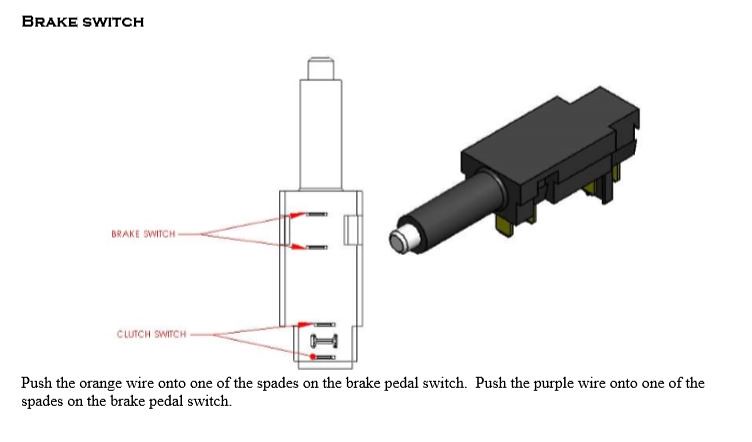
    That looks correct except for the brake light wire. Check the brake safety switch and be sure you have the wires attached to the proper spade connectors and that the switch is engaged when the brake pedal is in the resting position. There are two sets and the clutch and brake switches are wired opposite each other.


    The horn goes through a relay and the horn button typically is just triggering the relay. The flasher and turn signal feed wires should be hot as they feed the switches.

    Dave
    Last edited by Papa; 06-23-2018 at 04:17 PM.
    My Build Thread: http://thefactoryfiveforum.com/showt...ter-Build-9754
    (Most viewed Roadster build thread on this forum!)

    Delivered: 6/17/2017
    First Start: 12/30/2017
    Completed: 12/7/2019
    Legal: 1/30/2020

    Member of the Mile-Hi Cobra Club
    Dave's Cobra YouTube Channel: https://www.youtube.com/channel/UCbk...npK1UZHj4R-bYQ
    Agora 1:8 Scale Cobra Build: https://thefactoryfiveforum.com/show...l-Build-Thread

  22. #22
    Senior Member TomH33's Avatar
    Join Date
    Nov 2016
    Location
    Parker,CO
    Posts
    108
    Post Thanks / Like
    Hi

    At it again, I unplugged the brake light switch and the purp/blk wire on the column plug is now at 0 voltage.

    When I plug in the column harness with the key on I get opposite directionals working. Left is right and right is left. They both work perfect on the wrong side. According to the markings on the harness wire I have the right loom on the drivers right side and the left on the drivers left. Not sure what is going on.
    I'll continue trying. Thanks for the help.
    TomH33

  23. #23
    Consummate Learner TxMike64's Avatar
    Join Date
    May 2017
    Location
    Kingsland, TX
    Posts
    425
    Post Thanks / Like
    Blog Entries
    1
    The drivers side is the LEFT side of the car.
    -- Mike -- TxMike64 -- @TxMGarage
    Gen1.5 Hot Rod '33 #1094 (Stage 1) - 302/AOD '15 IRS - Quad Built - Build Thread

  24. #24
    Senior Member TomH33's Avatar
    Join Date
    Nov 2016
    Location
    Parker,CO
    Posts
    108
    Post Thanks / Like
    Hi Again

    Well t has taken me a while to find all the problems but all is well that ends well. I had a friend that is am electrical engineer and we pulled the harness an ran through all connections. He found miss wiring in the directional part. Something about the right rear signal wire was connected the left front. He changed 2 wires on the column connection to correct left and right. I now have all electrical: tail, parking, brake and turn signals. I did wire the headlight to a separate set of relays but work perfect.

    This brings me to a new problem. I pulled the tail lights out and had a look. Of course there are no Instructions in the manual or with the lights. I took my probe and applied 12V using the blk for ground, nothing. So I chose the white (like house wiring) for ground and the Red wire seems to be brake lights, the black seems to be tail lights and no wire for directionals. How are you attaching the purple brake light wire, the beige tail/parking light wire and the yelo/white (L/R) directional wires. Do two of these pair up for directionals or what.

    Thanks again for all your help
    TomH33

  25. #25
    Papa's Avatar
    Join Date
    Dec 2016
    Location
    Mexico, MO
    Posts
    5,678
    Post Thanks / Like
    This post by Jeff Kleiner might help even though it's for the roadster. The harness is the same, just not sure what your light colors might be.

    In the rear:
    The Ron Francis harness is set up so that all 4 lamps are illuminated for tail lights with one on each side used for brake lights and the other on each side used for turn signals. I prefer to orient them so that the uppers are brake lights for better visibility. When using that configuration:

    ---Tan harness wire at each corner is for tail lights and will go to the low element on all four light assemblies via the red/yellow lamp wire.

    ---Purple harness wire at each corner is for brake lights and will go to the bright element on the upper light assembly per side via the green lamp wire.

    ---Yellow harness wire on the driver's side is for left turn and goes to the bright element on the lower light assembly via the green lamp wire.

    ---White harness wire on the passenger side is for right turn and goes to the bright element on the lower light assembly via the green lamp wire.

    ---Black wire on all joins with the black harness ground.

    In front:

    ---Tan harness wire at each corner is for the amber parking/running lights and will go to the low element on both light assemblies via the red/yellow lamp wire.

    ---Dark green harness wire on the driver's side is for left turn and goes to the bright element on the light assembly via the green lamp wire.

    ---Light blue harness wire on the passenger side is for right turn and goes to the bright element on the light assembly via the green lamp wire.

    ---Black wire on both joins with the black harness ground.
    My Build Thread: http://thefactoryfiveforum.com/showt...ter-Build-9754
    (Most viewed Roadster build thread on this forum!)

    Delivered: 6/17/2017
    First Start: 12/30/2017
    Completed: 12/7/2019
    Legal: 1/30/2020

    Member of the Mile-Hi Cobra Club
    Dave's Cobra YouTube Channel: https://www.youtube.com/channel/UCbk...npK1UZHj4R-bYQ
    Agora 1:8 Scale Cobra Build: https://thefactoryfiveforum.com/show...l-Build-Thread

  26. #26
    Senior Member Big Blocker's Avatar
    Join Date
    Feb 2011
    Location
    Lost Wages, Nevada
    Posts
    634
    Post Thanks / Like
    Quote:

    In the rear:

    ---Tan harness wire at each corner is for tail lights and will go to the low element on all four light assemblies via the red/yellow lamp wire.

    ---Purple harness wire at each corner is for brake lights and will go to the bright element on the upper light assembly per side via the green lamp wire.

    ---Yellow harness wire on the driver's side is for left turn and goes to the bright element on the lower light assembly via the green lamp wire.

    ---White harness wire on the passenger side is for right turn and goes to the bright element on the lower light assembly via the green lamp wire.

    ---Black wire on all joins with the black harness ground.

    In front:

    ---Tan harness wire at each corner is for the amber parking/running lights and will go to the low element on both light assemblies via the red/yellow lamp wire.

    ---Dark green harness wire on the driver's side is for left turn and goes to the bright element on the light assembly via the green lamp wire.

    ---Light blue harness wire on the passenger side is for right turn and goes to the bright element on the light assembly via the green lamp wire.

    ---Black wire on both joins with the black harness ground.


    Yup . . . Correct. Checked, double checked and verified.

    Only thing I can think to add; Your dash indicators tie to the front TS circuit(s)

    Doc
    Last edited by Big Blocker; 07-17-2018 at 11:52 AM.
    FFR3712K (MKII) in Lost Wages Nevada.
    5.0 w/tubular GT-40 EFI, E303 cam, Custom 4 into 4 headers, T5, 3-Link 3.73 rear. Full F5 tubular suspension. Drop Butt mod, Dash forward mod, custom foot box air vents, custom turn signal system. 13" PBR brakes, Fiero E-Brake mod, Flaming River 18:1 rack w/ F5 bump steer kit on Breeze bushings. 17" Chrome Cobra "R's" w/ 275 fronts and 315 rears. MKIV seats. FORD Royal Blue w/ Arctic White stripes.

  27. #27
    Junior Member
    Join Date
    May 2013
    Location
    Pittstown NJ
    Posts
    11
    Post Thanks / Like
    From manual: The color coding for the lights is: White (Ground), Black (Running light), Red (Stop/Turn signal). This is in the back of the book for some reason.
    Also "Cut the yellow and white rear turn signal light wires off the turn signal connectors that are for the dash turn signal switch so that the turn signal lights do not back feed and light the front turn signals when the brakes are pressed
    Good luck,
    tommy23t

Posting Permissions

  • You may not post new threads
  • You may not post replies
  • You may not post attachments
  • You may not edit your posts
  •  

Stewart Transport

Visit our community sponsor