Midwest Classic Insurance

Visit our community sponsor

Thanks Thanks:  0
Likes Likes:  0
Page 1 of 6 123 ... LastLast
Results 1 to 40 of 204

Thread: Frame Mods to Type 65 Coupe

  1. #1

    Join Date
    May 2011
    Location
    Salt Lake City, UT
    Posts
    755
    Post Thanks / Like

    Frame Mods to Type 65 Coupe

    I'm going to be making some frame mods to my new coupe, with the goals of 1) adding door bars to make it legal for SCCA, NASA and ECTA racing; 2) making it safer to crash (not that I'm planning on it); 3) making it as stiff as possible, within reason; and 4) making it mine, so to speak. I've read the foregoing rulebooks, I believe that I understand what each requires, and I have the correct tubing (1.5" x .120 DOM) on hand.
    The pictures below illustrate, somewhat crudely, a little bit of what I'm thinking of doing to achieve goals #2-4. I'd really appreciate hearing if anyone thinks that what I'm thinking is a good idea, a complete waste of time, not enough of a benefit to justify the extra weight, etc. Do not hesitate to point out if something will be little more than decorative. I don't want to reinvent the wheel here, and tube chassis design is far from my area of expertise. I'd also appreciate any photos from folks who have done essentially the same thing, particularly door bars, as I am at the early stages of figuring out how to add them. Thanks in advance for your thoughts.
    Roll Bar Additions 3Roll Bar Additions 4.JPG
    I plan to make the cross-bar on the two rear bars removable with Ballistic Fabrication connections, which should let me install the trunk floor panel without too much hassle. As for the additional bars connecting the front and back hoops, would there be any benefit to doing one diagonal bar from the left front to the right rear (somewhat in line with how the chassis twists under a hard launch)?
    IRS Gussett 1IRS Gussett 2.JPG
    Is there anything that I might want to gussett back here? The car will probably make about 350 horsepower in its first iteration (331 c.i.). Twenty years from now, it'll likely have a little more!
    IRS Brace 1IRS Brace 2.JPG
    Adding a bar in here seems like it would stiffen the rear frame a decent amount. Any downside? From everything I've seen it wouldn't interfere with anything (gas tank, battery), but I'd rather find that out now!
    left front gussettleft front gussett 2.JPG
    Part of me thinks that the gussetts will be overkill; part of me doesn't. Any thoughts would be welcome.

    Jacob McCrea

  2. #2
    Senior Member Mike N's Avatar
    Join Date
    Feb 2011
    Location
    Mooresville NC
    Posts
    801
    Post Thanks / Like
    Jacob do a search under frame mods here and on the other forum. turbodon (Don Vaught) and David Borden and others have done some great work on chassis improvements using some quite detailed structural modelling techniques. What you are considering is obviously good for strength but if you want improvements in stiffness there are other areas that are a lot more beneficial. Here's a thread by David Borden that contains some really good info relative to the MkIV which also applies somewhat to the Coupe. http://thefactoryfiveforum.com/showt...ght=frame+mods
    Mike............

    FFR2100 - 331 with KB supercharger - T5 - 5 link rear 3.08's and T2 Torsen.

  3. #3
    Super Moderator

    Join Date
    Feb 2011
    Location
    Richmond, ca.
    Posts
    393
    Post Thanks / Like
    I agree with Mike, check out what others have done. Dave Bordens stuff mostly relateds to the roadster frame but there are many carry overs . The gussets should help and look cool IMHO! :-)
    Last edited by Russ Thompson; 06-24-2011 at 07:48 PM.

  4. #4
    Trick Tool Maker, Super Moderator Hankl's Avatar
    Join Date
    Feb 2011
    Location
    Northern CA
    Posts
    671
    Post Thanks / Like
    Blog Entries
    1
    The one problem I see in the first picture is the location of the bar in the halo, closest to the drivers head. Clearance is very limited in that area, so I would see value in the center bar, but not the one closest to the drivers head. The tunnel structure can also be an area of improvement, along with some stiffening from the foot boxes to the "X" upright.

    Hank
    “If you didn’t have enough time to do it right the first time. How come you always have time to go back and do it again?” FFR1000186CP

    Understeer is when you hit the wall with the front of the car and oversteer is when you hit the wall with the rear of the car.
    Horsepower is how fast you hit the wall and torque is how far you take the wall with you.

  5. #5

    Join Date
    May 2011
    Location
    Salt Lake City, UT
    Posts
    755
    Post Thanks / Like
    Guys, thanks for the responses; they are greatly appreciated.
    Mike, I was amazed by David Borden's frame mods, as well as how stiff the Roadster chassis is right out of the box. It makes me wonder if I should just add door bars and send my chassis out for powdercoating.
    Russ, those gussetts are from Ballistic Fabrication, a 4x4 shop out of Tucson, and are available in a few different angles. At $5 each they're a good deal and will help to save some precious time.
    Hank, I agree with your concerns about the overhead bars; I have read (and believe) that an ill-placed overhead bar would likely add danger. I may do just one bar, front to back, right down the middle. I was thinking about a diagonal bar, from left front to right rear, but am concerned that I'd be shifting the danger from myself to a passenger, who should not have to wear a helmet just to take a ride around town. I will add the bracing from the "X" uprights to the footboxes, which seems pretty straightforward.
    I'll post what I do on this forum. Thanks again for your much-appreciated input.

  6. #6
    Trick Tool Maker, Super Moderator Hankl's Avatar
    Join Date
    Feb 2011
    Location
    Northern CA
    Posts
    671
    Post Thanks / Like
    Blog Entries
    1
    Jacob,

    Here's a picture of how Carl did the center bar in his Coupe.


    Hank
    “If you didn’t have enough time to do it right the first time. How come you always have time to go back and do it again?” FFR1000186CP

    Understeer is when you hit the wall with the front of the car and oversteer is when you hit the wall with the rear of the car.
    Horsepower is how fast you hit the wall and torque is how far you take the wall with you.

  7. #7

    Join Date
    May 2011
    Location
    Salt Lake City, UT
    Posts
    755
    Post Thanks / Like
    Folks,
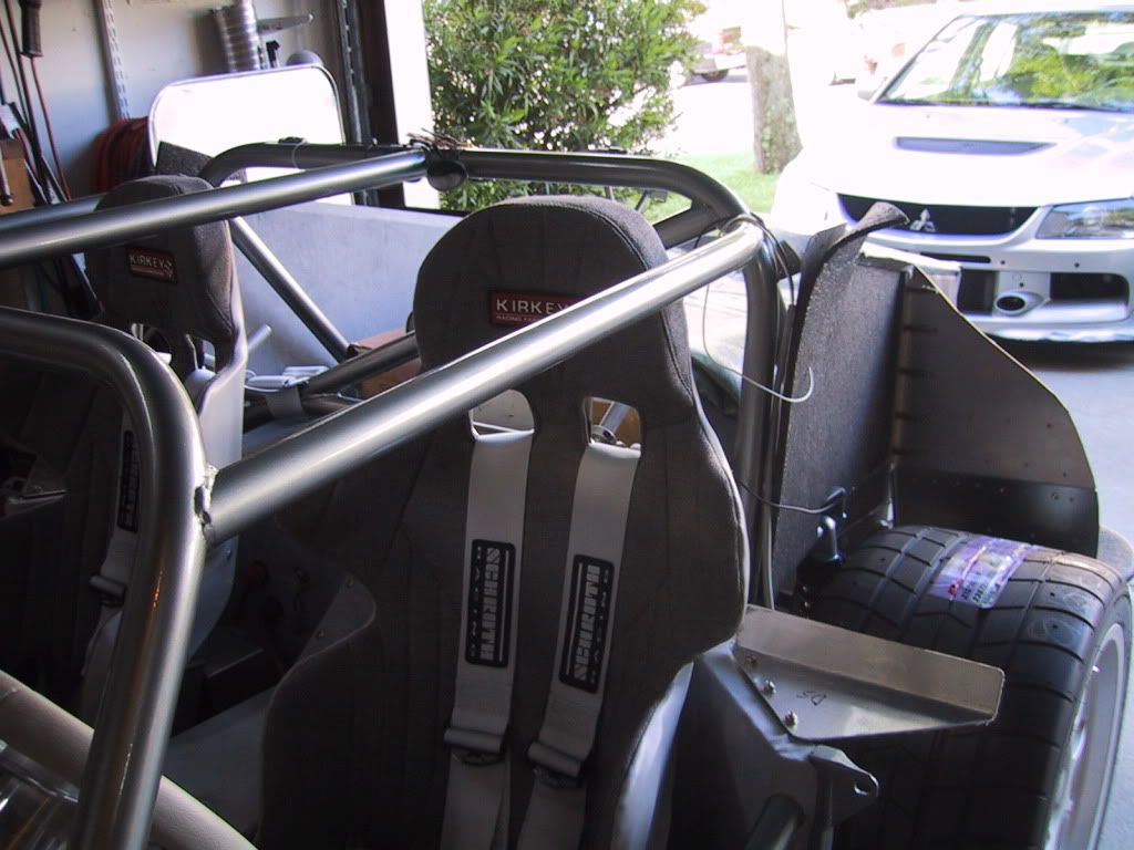
    Here is a picture of some recent progress on the frame mods. Everything is tacked in place for now and will be welded solid shortly. If you look closely you can see the Ballistic Fab connectors on the rear new cross tube. The connectors worked really well and will likely be used on the X bars across the doors.
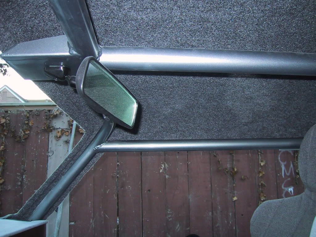
    For whatever reason, I couldn't resist the urge to install the additional roof tube at a slight angle. I put the Kirkey seats in before deciding on this and the head clearance is still better than the distance between the seats and the "outside" bars.
    Two tools which I used for the first time, and which worked really well, were a Starrett angle finder (made for carpenters, I think) and a JD Squared Notchmaster tubing notcher. The latter seems like it was well worth the extra money compared to the entry level notchers.
    The next steps are to fabricate and weld in a tie down loop behind where the differential mounts, weld in a Forte's driveshaft loop and finish the tubes from the footboxes to the "X" uprights. I got one cut today but was unable to tack it in place. From there I'll fill in a few open tube ends and install the door bars. As always, constructive criticism is welcome. Thanks for checking this out.
    Attached Images Attached Images

  8. #8

    Join Date
    May 2011
    Location
    Salt Lake City, UT
    Posts
    755
    Post Thanks / Like
    Here are a few recent progress pictures.
    Drive Shaft Loop.JPG

    The Forte's driveshaft loop is a well made part; the fit and finish are very good. I elected to weld it in because it was easier and faster. I chose to install one after recently seeing a rear u joint let go on a really tall full-size truck that had just passed me. It was quite a sight to see. Also, at the left you can see a 1 1/4" tube I added for mounting either the "tow eye" suggested by NASA rules, or a parachute.

    Left Front Frame.JPG

    I added these bars, as suggested by Hank L., by following David B.'s design on his MkIV thread. I thank Hank L. and David B. for sharing their knowledge of frame mods. This evening I also completed changing the 1" square tube to 2", and I'm considering tying the two together at an angle with a round tube. I will post pictures when the other side is done.

    Tie Down Loop.JPG

    Nothing all that special here; just a tie down loop that I added before I realized that the 1 1/4" square tube could serve the same purpose. Thanks for checking this out.

  9. #9
    Senior Member riptide motorsport's Avatar
    Join Date
    Feb 2011
    Location
    Fort Lauderdale Fl.
    Posts
    3,296
    Post Thanks / Like
    Lookin good!
    FFR Daytona Type 65 Coupe
    67 427 Cobra
    57' Belair
    72 Pinto Wagon ,306" 1/4 miler
    34 5 window coupe Ford
    2003 Mustang GT
    99' ZX9
    85 Goldwing

    All toys still in the Scuderia!


    Every Saint has a past..................every sinner a future

    Don't take yourself so seriously........no one else does.

    You never see a motorcycle parked outside a Psychiatrists office.

  10. #10

    Join Date
    May 2011
    Location
    Salt Lake City, UT
    Posts
    755
    Post Thanks / Like
    Here are some more progress photos. The 1" tubes from the dash area to the front suspension towers are now 2" x .120. This should stiffen the frame a little without the complexity of adding more tubing from the roll cage to the suspension towers. This will require some modifications to the footbox aluminum. This is not my original idea; Gordon Levy was generous in sharing his knowledge with me and I appreciate his advice.

    Driver Side.JPG

    I may add two more tubes connecting the new lower tubes to the new 2" square tubes at an upward angle from front to back. I am not sure if I would gain anything beyond what I have already done.

    Passenger Side.JPG

    I had to remove a fair amount of metal to fit the tube to this section of the frame. It looks like I will have to weld a stud into the frame for one of the attaching bolts if I want to use the Mustang pedal box, since the 2" tube prevents installing a bolt from the outside. I may go with Wilwood pedals and master cylinders in the end.
    Driver Side Footbox.JPG

    I went with a Type 65 for a lot of reasons, one of which was that I didn't want to do the frame/sheet metal work to make a muscle car handle like a sports car. Well, nevertheless, here I am with a carpet of metal shavings, mig wire and grinding wheel debris on my garage floor. Thanks for checking this out.

  11. #11

    Join Date
    May 2011
    Location
    Salt Lake City, UT
    Posts
    755
    Post Thanks / Like
    Attached are photos of protective tubing that I added in the gas tank/fuel cell area. As with the other frame mods, the round tubing is 1.5" x .120 DOM. The placement of these tubes was a compromise between 1) wanting to make them as low on the frame as possible; 2) making this a fairly easy mod to accomplish; and 3) making sure that both the stock Fox Mustang tank and the 22 gallon Fuel Safe cell that is typically used with Roadsters and Coupes will fit. The Mustang tank fits just fine, but by my measurements I would have to move the Fuel Safe cell forward by about 3/4" from where (I think) it would otherwise sit, and probably make some mounts to attach it. This is because the new rear tube intrudes into that area by about 3/4".

    If I had to do it again, I might weld the forward-facing tubes directly to the back of the frame rails, rather than widening the ends of the quad shock mounts and welding the tubes to that area. This would solve the (likely) 3/4" interference issue, but would provide a little less protection for the stock Mustang tank since the new tubes would be entirely above it. Anyway, here are the photos.

    Fuel Cell Protection 1.JPG
    Fuel Cell Protection 2.JPG
    Fuel Cell Protection 3.JPG

    I would prefer to post these as actual images in the posts, rather than attachments which can only be viewed upon login, but haven't figured out how to do it. If someone can help me with this via a private message, I would really appreciate it.

  12. #12

    Join Date
    May 2011
    Location
    Salt Lake City, UT
    Posts
    755
    Post Thanks / Like
    And here are some photos of the most recent additions to the front of the frame. I tied the newly replaced 2" x 2" tubes to the new 1.5" tubes with 1.5" tubing, at an angle, on each side. I left a bit of room to facilitate header installation. Also, if you look at the two photos immediately below you can see some tabs, with nuts welded on them, that I added to the footbox tubing so that aluminum plate can be bolted in for more footbox/side impact protection.

    Left Frame 1.JPG

    Left Frame 2.JPG

    In the photo below you can see a short piece of tube, maybe 4" long, that I added to tie the outer footbox tubing to the 2" square tubing. The objective was a little more side impact protection (although I have faith in the factory design and hope that my mods aren't taken otherwise). I'm not sure if it will do much for stiffness, but it can't hurt.

    Left Frame 3.JPG

    I added a similar tube to the passenger side as well, to keep both sides consistent in terms of how the footboxes are connected to the 2" square tubing. I have the new upright tube welded in so that it will be just inside of the footbox aluminum on this side. I am trying to keep footbox aluminum mods to a minimum.

    Right Frame 1.JPG

    Right Frame 2.JPG

    As always, thanks for checking this out and feel free to post any constructive criticism.

  13. #13
    Trick Tool Maker, Super Moderator Hankl's Avatar
    Join Date
    Feb 2011
    Location
    Northern CA
    Posts
    671
    Post Thanks / Like
    Blog Entries
    1
    Jacob,

    Nice work, great minds think alike!! On the fuel cell area, that is also a good way to set up a tow ring for the rear, as that is a requirement under the SCCA/NASA rules, you're already there!!

    (P.S. put gussets on the inside corners to help the flexing side to side)


    Hank
    “If you didn’t have enough time to do it right the first time. How come you always have time to go back and do it again?” FFR1000186CP

    Understeer is when you hit the wall with the front of the car and oversteer is when you hit the wall with the rear of the car.
    Horsepower is how fast you hit the wall and torque is how far you take the wall with you.

  14. #14
    Super Moderator vnmsss's Avatar
    Join Date
    Feb 2011
    Location
    California
    Posts
    649
    Post Thanks / Like
    Blog Entries
    13
    It's so cool to see the development of a competition-level coupe chassis and cage. I've had so many coupe owners and potential owners e-mail or PM over the last few years looking for the race spec on a cage and competition level safety systems....You guys are my heroes! Nice work everyone!!!!

    Karen
    Last edited by vnmsss; 09-08-2011 at 01:14 AM.
    #28 FFR Challenge Series
    #28 FFR Type-65 Coupe
    2011 Western Endurance Racing Championship
    2010 West Coast Champion
    Drive it.....Like you stole it!

  15. #15

    Join Date
    May 2011
    Location
    Salt Lake City, UT
    Posts
    755
    Post Thanks / Like
    Karen, Hank and Steven,
    Thanks for the generous compliments; they are very much appreciated, especially considering the sources. I'm humbly following in the footsteps of everyone who has done this before me, and am happy to see that folks are enjoying the posts. I will keep them coming to try to give back some of the massive amount I've learned here and on the other forum (both of which are allowing me to build a better car than I otherwise could).

    The next steps are door bars and figuring out whether the Wilwood pedals will interfere with my newly replaced 2" x 2" frame tubes to the shock towers. Bob (rj35pj) posted a thread today about that issue and was kind enough to discuss it with me at length this evening. The bottom line: it looks like I have a problem if I want to use Wilwood pedals (and I'm pretty sure that I do). I will get to the bottom of that and post what I find. Thanks again for the compliments.

  16. #16

    Join Date
    May 2011
    Location
    Salt Lake City, UT
    Posts
    755
    Post Thanks / Like
    To follow up on the post above, I confirmed that the Wilwood pedals do interfere with the 2" square tubes from the roll cage bulkhead to the front suspension towers. I have the fix figured out and partially implemented, but in the meantime here is an overview of what is required to install the 2" tubes in the first place, and to use the Mustang pedal box.
    First, I fully removed and replaced one tube before doing the other, just in case there was a lot of tension built up in the tubes. Acually, when I cut each of them, they compressed ever so slightly on the Sawzall blade, but not enough to stop it from reciprocating.

    To make it easier to fit the tubes, I clamped a piece of aluminum angle to the front suspension towers to act as a "shelf" for the new tubes to rest on as I fit them. I tacked them in place with the ends sitting on the "shelf", then removed it for final welding. I forgot to take a picture of that.

    Cutting the old tubes off of the door hinges and preparing that area for welding was the hardest part. It required a lot of careful, time-consuming work with a cutoff wheel, a die grinder, and a 5 inch grinder. On the driver's side, you will need to cut the door mount in half and remove the top piece with a cutoff wheel, as shown in the picture below (rewelded), because the 2" tube will not slide in from the inside. On the passenger side it is not a problem - it will slide in from the inside. Of course, you need to weld the door mount back on after the new 2" tube is in place! I used 3/16" plates clamped to each side to prevent distortion while welding.
    Rewelded Door Mount.JPG

    I had to use a 5" grinder and remove a little bit of material from the front suspension tower, where the pencil in this photo is pointed, to get the mig gun close enough to make a pass. The strength shouldn't be decreased enough to matter.
    Front Frame Clearance.JPG

    The 2" tubes are simply incompatible with a vacuum brake booster since even the original 1" tube needs to be cut on the driver's side. But, as far as I can tell from fitting up a regular master cylinder and studying photos of others' builds, a hydroboost unit would still fit, albeit tightly. But, you would want to confirm this for yourself if you make this change.

    To use the Mustang pedal box you will need to notch the lower left bolt hole area. I am not using it, but I feel some obligation to show what's needed to use the Mustang box. You will also need to weld a stud into the same hole because there isn't enough room to get a bolt, or even a nut, on the outside of the footbox. Here are the photos:

    Modified Pedal Box.JPG

    Pedal Box Stud.JPG

    To weld that stud at a 90 degree angle, I threaded a riv-nut from my driveshaft loop kit onto the stud and pressed it tight against the footbox front plate. I set the stud in about half way so I got a decent amount of heat built up by the end of the weld. It came out just fine.

    Also, you might need to take a little nick out of the Mustang clutch pedal to clear the new tube. And of course, some changes to the footbox aluminum are needed. As far as I can tell, this covers what one would need to modify to use the Mustang pedal box. To use the Wilwood pedals, as I've chosen to do, I had to make a MIND NUMBING array of changes, starting with relocating the steering shaft bearing 1" to the inside. I will cover those changes in forthcoming posts. Thanks for checking this out.
    Last edited by Jacob McCrea; 10-29-2011 at 11:12 PM. Reason: Typos

  17. #17
    Senior Member rj35pj's Avatar
    Join Date
    Mar 2011
    Location
    Marion, IN
    Posts
    301
    Post Thanks / Like
    Jacob,
    Nice work! You and some of the other guys doing the extra frame work make me think about mine....if I build another one....I may be calling you for advice. Keep the photos and info coming
    Bob

  18. #18

    Join Date
    May 2011
    Location
    Salt Lake City, UT
    Posts
    755
    Post Thanks / Like
    Thanks Bob. At the rate you are going you'll be building a second coupe before mine is done.

    Here are some photos of how the headers fit with the new tubing - plenty of room! I considered adding a cross-tube here to make a full "X" but I really don't want to add any more weight to the car.

    Left Header Clearance.JPG Right Header Clearance.JPG

    Also, this is hardly ground-breaking, but is useful enough that I thought I'd share it. I had my chop saw set at 90 degrees and had no interest in re-setting it for each angle cut, so I made this thing to clamp to the top of the saw. It is two pieces of 2" wide flat steel welded together via a door hinge from the hardware store. The stationary side clamps to the back of the chop saw with a Vise Grip, while the other is adjustable and, once set to the desired angle, clamps to the base with another Vise Grip. There is a piece of angle iron welded to the adjustable side so that it can be clamped to the base. The saw's existing work clamp still works pretty well at an angle. It saves some time that I'd otherwise spend adjusting the chop saw (or having my fingertip reattached when the piece being cut slips). Thanks for checking this out; I'll keep the photos coming.

    Chop Saw Angle.JPG

  19. #19

    Join Date
    May 2011
    Location
    Salt Lake City, UT
    Posts
    755
    Post Thanks / Like
    And here are some photos from making the Wilwood pedals work with my oversized square tubes from the front loop bulkhead to the front suspension towers. When I changed from 1" square tubes to 2" square tubes, the Mustang pedals still worked with minor mods, as described above.

    Using the Wilwood pedals is another story and the required changes honor the straight jacket. In short, the clutch pedal won't even move in the stock location because it is right against the 2" square tube. I needed to tilt the front of the pedal assembly forward by approx. 1/2", then move it back approx. 3/4", then move it to the inside by approx. 7/8", then move the adjustable pedal pads all the way to the outside so they don't get too close to the gas pedal.

    Sounds easy enough, sort of, but for the fact that the brake pedal then bangs into the steering shaft. So, I moved the lower steering shaft bearing to the inside by 1" - no small feat. I also moved the assembly back far enough that the clutch pedal would hit the 2" tube around the same time that the master cylinder ran out of travel. If the clutch won't disengage, I'll simply switch to a bigger master cylinder for the hydraulic clutch (3/4" was what was supplied by Forte's). It might make the pedal harder, but I'm not concerned.

    On top of all of that, I needed to take the bends out of Russ Thompson's pedal arm, move the pivoting attachment to the other side of the pedal arm, plug weld the throttle cable hole, and drill a new hole for the throttle cable approx. 1" to the inside. It was unpleasant to put that nice pedal arm in a vise.

    Setting up the Steering Shaft.JPG Circular Patch.JPG New Steering Hole Completed.JPG Fitting the Pedal Box.JPG

    In the first photo above you can see the copper plates that I used as a backing to put the "plug" in place and weld up the old steering hole before drilling a new one. Using copper as a backing to do plug welds is an old body man's trick because the copper doesn't stick to the weld. But, as I found out, at a certain point that's no longer 100% accurate and the two do start to stick. It seems to work fine up to 1/4" holes, but after that the copper was a little more likely to stick to the weld.

    With the steering shaft bearing moved, I had to fabricate new mounts for the pedal assembly. The driver's side was simply a piece of 3/16" x 2" cold rolled steel welded to the 2" tube, then drilled and tapped. I went with cold rolled because it is stronger and I wanted to tap the threads. I used the same steel on the other side, but had to bend it twice and weld it to the existing tube and front of the footbox, as shown below. The gusset is there to reduce flex. I know from bicycle racing that flex in the brake system robs a lot of stopping power. Granted, this is no bicycle, but I think the conept is sufficiently universal to warrant making the footbox mounts as stiff as possible.

    Finished - From Outside.JPG Installed - Inside View.JPG

    The fit for all of this was so tight that I had to tape thin paint sticks to the steering shaft and one of the 3/4" footbox tubes to make sure that I had enough room when everything was either welded solid or bolted in. It took a lot of thought to make this work and hopefully the added stiffness and braking will be worth the considerable effort.

    I elected to use Wilwood pedals after studying an excellent thread on the other forum about "good brakes on a budget." It's a really interesting read and I would suggest it to anyone who is figuring out what brakes to buy. I have to add that I need to run a hydraulic clutch because a Wilwood manual clutch setup would occupy the same space as a "forward bar" that I need to run through the top of the footbox and out to the front suspension towers to meet SCCA rules (at least as I read them). If I wanted to run Wilwood pedals and a cable-operated clutch, I would have to re-configure where I'd run the forward bars. Frankly, I'm not sure that I could do that with the available space. In hindsight, I might have used 1.5" x .120 DOM tubing in place of the 2" square tubing and just dealt with the other problems that would have been created by that course of action. But what's done is done and the round tubes would have created their own set of issues. I will post a few more pics shortly. Thanks for checking this out.
    Last edited by Jacob McCrea; 10-29-2011 at 11:16 PM. Reason: A few more details and clarity

  20. #20
    Senior Member xlr8or's Avatar
    Join Date
    Feb 2011
    Location
    San Diego CA
    Posts
    318
    Post Thanks / Like
    Nice work.
    It's never too early to start beefing up your obituary.

  21. #21

    Join Date
    May 2011
    Location
    Salt Lake City, UT
    Posts
    755
    Post Thanks / Like
    Thanks for the compliments. Here are a few more photos from making the Wilwood pedals fit with the frame modifications.
    It was a little chilly in the garage so I pre-heated the metal just a little. It helps to prevent the start of the weld bead from being too cold, and therefore weak. I also think it is good to burn off any traces of moisture on the surface, but that's just my own unsupported opinion.
    Little Bit of Heat.JPG

    I made and used this paper pattern to double-check my measurements for making the new hole for the lower steering shaft bearing. Nice and simple!
    Paper Template.JPG

    The black square tube is an alternative inner pedal box mount that I tried, but it interfered with the gas pedal, so I went with an alternative design using the 2" x 3/16" cold rolled flat steel.
    First Attempt at Inner Mount.JPG

    If you look closely you can see where a 3/4" x 3/4" cross-tube was removed in order to move the pedals back.
    Cross Tube Removed.JPG

    Nothing special here, just drilling and tapping one of the holes.
    Drill and Tap.JPG

    The new steering bearing hole.
    Back Side of Footbox.JPG

  22. #22
    FFR Rookie Craftsman
    Join Date
    Jul 2011
    Location
    Bugtussell, AR
    Posts
    37
    Post Thanks / Like
    Howdy Jacob,

    Nice work!

    With all your frame mods, will you be able to use any of the factory aluminum panels?

    My Spyder has a highly modified frame and none of the factory panels will fit and I'm in the progress of making new panels.

    Keep up the great work!

    Paul
    FFR 4859GT 414W (stroked 351W, 4.0" stroke, 4.060" bore). Tremec TKO 5spd. IRS w/3.55 and Torsen diff. 13" dual-piston front disc brakes (Mustang Cxxxra parts), 12" rear disc brakes (Corvette parts). 2003 Mustang Coxxa wheels, 275/40 front, 315/35 rear.

    Possibly the only person in the world that is currently building a Spyder GT.

  23. #23

    Join Date
    May 2011
    Location
    Salt Lake City, UT
    Posts
    755
    Post Thanks / Like
    Thanks for the compliment, Paul. It looks like your Spyder is moving along very nicely. Those headers are unbelievable!

    I think I'll need to make a new panel for the front of the driver's footbox, but that's more the result of the lack of a master cylinder sticking out of it than anything else. I think (and we'll see if I'm right) that everything else can be trimmed and tweaked to fit. The top of the passenger's footbox will need to be lowered approx. 1/2 inch in the front because the 2" square tube runs at a little different angle. Using square tubing, rather than round, made attaching the passenger footbox easier, but the square tubing does not comply with SCCA rules for tubing in that area, so I'll need to add a DOM tube about 5" above it if I want an SCCA-compliant cage, at least as I read the rules. Also, I think I'll build the footboxes to accept a modular engine, even though I'm using a 331, since I plan to own this car until my last day.

    Anyway, here are a few more frame mod photos. These were added to the outside of the 2x2 outside framerails to give me more area to mount the interior aluminum panel that runs from the door sill to the frame. The factory panel comes in at an angle; I want it to go straight down so that I have more room to attach Nascar-style door bars and the aluminum panel. It's 1/8" x 1" cold rolled steel. In the photos, they are not welded in. Thanks for checking this out.

    New Edge for Aluminum 3.JPG

    New Edge for Aluminum 2.JPG

    New Edge for Aluminum 1.JPG

  24. #24

    Join Date
    May 2011
    Location
    Salt Lake City, UT
    Posts
    755
    Post Thanks / Like
    I know everyone likes pictures, so here are a few more from recent progress. The one immediately below is a pedal stop that I added so that the clutch pedal doesn't crash into the 2x2 tube at the very end of its travel. I mounted the pedal box so that the clutch pedal hit the frame at the same time that the master cylinder ran out of travel, but I still needed to physically stop the pedal from hitting the frame. It's 3/16" cold rolled steel, shaped to fit, and probably stronger than necessary, but I wasn't sure how well 1/8" steel would tap. I guess I could have put nuts on each side of the bolt, but what's done is done.

    Clutch Pedal Stop.JPG

    Here is the dead pedal I welded in - again, 3/16" cold rolled steel. The shiny pads are replacement pedal pads from Wilwood. They were less than $9 each, so it didn't make much sense for me to fab something.

    Dead Pedal 1.JPG

    Dead Pedal 2.JPG

    I recently came up with a few ideas for taking off some of the weight that I've been adding. Hopefully I'll have more photos before too long. Thanks for checking this out.

  25. #25
    Senior Member riptide motorsport's Avatar
    Join Date
    Feb 2011
    Location
    Fort Lauderdale Fl.
    Posts
    3,296
    Post Thanks / Like
    Just excellent work.
    FFR Daytona Type 65 Coupe
    67 427 Cobra
    57' Belair
    72 Pinto Wagon ,306" 1/4 miler
    34 5 window coupe Ford
    2003 Mustang GT
    99' ZX9
    85 Goldwing

    All toys still in the Scuderia!


    Every Saint has a past..................every sinner a future

    Don't take yourself so seriously........no one else does.

    You never see a motorcycle parked outside a Psychiatrists office.

  26. #26

    Join Date
    Feb 2011
    Location
    Colorado Springs
    Posts
    1,393
    Post Thanks / Like
    Way cool, and fascinating. I have one suggestion, and a couple of questions.

    After playing around with it, I'v found that the dead pedal works best just slightly behind the clutch pedal, closer to me. It's comfortable, and any easy/quick transition from one pedal to another. But maybe that's just me.

    I was fascinated to how see you used the software to figure out where to put the additional bars. That's way beyond my skills. Fitting some of the new braces is probably beyond my skills, too. Because I am ignorant in this area, it got me to wondering. You added all the braces to make the chassis stiffer, and that adds weight. Do you think the car will be faster? or slower? Or will the two balance out, and make the car more precise and easier to drive?
    .boB "Iron Man"
    NASA Rocky Mountain, TTU #42, HPDE Instructor
    BDR 1642: Coyote, 6 Speed Auto, Edelbrock Supercharger
    Member: www.MileHiCobraClub.com
    www.RacingTheExocet.com

  27. #27
    Tech Support, FFR Brian Z's Avatar
    Join Date
    Feb 2011
    Location
    Wareham MA
    Posts
    410
    Post Thanks / Like
    Jacob,

    Have you tested your turning radius with the addition of this tube?

    It looks like it would affect your turning radius at full lock. I am just curious. It looks like it would add alot of strength to the chassis!
    Last edited by Brian Z; 11-11-2011 at 10:04 AM.
    Brian Zakrzewski
    FFR Tech & Sales

  28. #28

    Join Date
    May 2011
    Location
    Salt Lake City, UT
    Posts
    755
    Post Thanks / Like
    Thanks for the input and compliments, guys; they are much appreciated.

    Bob, I may have the dead pedal back too far. I imagine I could make something that bolts to the existing dead pedal if that's the case. I'm 5' 10 1/2," with longer legs for that height. We'll see how it shakes out.
    As for the ideas, I've just been following the designs that David B. posted on his MKIV build thread, as well as suggestions from Gordon L. and Hank L. I know computers and software like most people know cars - I can turn it on and use it, but have only a dim understanding of how it works! So, I can't take credit for any computer analysis - that belongs to David B.

    Fitting the tubes was tricky, especially at an angle. It required a combination of taking my time, thinking through what I was doing, and constantly checking the fit to see where material had to be removed. I did more trial and error than someone who does this for a living. A good notcher - a JD Squared Notchmaster, was very helpful. It's also worth mentioning that the Notchmaster works on flat stock (like my dead pedal), while the entry level notchers apparently only allow you to notch tubing.

    As for the weight, I'm really not sure how it will pan out. Hopefully the added stiffness, which may or may not even be needed, will be worth the weight penalty. I know from assembling racing bicycles that you can start out with a 4lb carbon fiber frame and end up with a 20 pound bike if you don't select the parts with care, and this is no different. The car will be a street-legal track car, so some weight will be omitted - heater, A/C, carpet, etc. I think I'm getting to the saturation point with weight and am thinking about remaking the driveshaft loop, and perhaps a few other parts, out of aluminum.

    Brian, I considered whether those lower bars would limit my turning radius and I imagine that they will. My understanding is that I can add "rack limiters" to the steering rack to address that. I don't recall seeing adjustable bump-stops on any spindles, so I don't think I can rely on that. We'll see. It's certainly a situation where I'm "assuming the risk."

    I'll post pictures upon more progress. Thanks for checking it out.
    Last edited by Jacob McCrea; 02-12-2012 at 12:25 PM. Reason: Typo

  29. #29
    Super Moderator vnmsss's Avatar
    Join Date
    Feb 2011
    Location
    California
    Posts
    649
    Post Thanks / Like
    Blog Entries
    13
    Very nice work Jacob! Really appreciate the pics and narrative description. Your design, fabrication and technological skills are noteworthy....Team Thunder Valley Racing is very pleased to welcome your efforts into the "Coupe for the track" building community....We're sure gonna have some serious track cars out there next year...Can't wait for all of us to run together in the future! (I know Daytona Dan is ready now!!) We'll be out your way soon Dan! ;.)

    Karen
    #28 FFR Challenge Series
    #28 FFR Type-65 Coupe
    2011 Western Endurance Racing Championship
    2010 West Coast Champion
    Drive it.....Like you stole it!

  30. #30

    Join Date
    May 2011
    Location
    Salt Lake City, UT
    Posts
    755
    Post Thanks / Like
    Thanks for the compliments and warm welcome, Karen. I'm pleased to be part of this tremendously talented community, to say the very least.

    By the way, here is a little item I fabbed up last week. I noticed that when I pulled up on the master cylinders with my hands there was a little flex in the pedal box, so I made this brace to go from the top of the pedal box to the front of the footbox. It is 3/16" cold rolled steel and should reduce that last little bit of flex in the pedal box and mounts, while only adding a pound or so. I may make another out of aluminum at some point. Conceptually at least, I don't see it as any different than braided brake lines - the goal being to prevent wasting my foot's pressure on something other than moving the brake pads. When I get the car together I'll drive it with and without, and see if there's a difference. I don't imagine it will make a big difference given how strong the existing mounts are, but (for all I know) it might be more noticeable if thinner mounting brackets are used on the pedal box. As always, constructive criticism is welcomed, and thanks for checking this out.

    Pedal Box Brace 2.JPG

    Pedal Box Brace 1.JPG

  31. #31

    Join Date
    May 2011
    Location
    Salt Lake City, UT
    Posts
    755
    Post Thanks / Like
    I recently had the time to add the "front hoop to front suspension" bars required by S.C.C.A. rule 9.4(C)(2). This rule provides that "[o]ne tube must extend, from each front down tube, foreward to the firewall or through the firewall except in vehicles in Improved Touring, Showroom Stock, Spec Miata, and Touring. This tube, one on each side, must connect to the chassis at a point not more than 12 inches forward of the front axle centerline."

    Here are some of the photos. You can see the metal pieces that I clamped in place to set up "limiting points" for fitting the tubes. In doing so, I was able to make sure that I was putting the tube in the same spot each time that I test fit it and decided where to remove additional material.
    Forward Bars 1.JPG
    Here is the initial hole that I drilled for the bar to pass through; I had to ream it out quite a bit at the top to allow enough movement to properly fit the tube.
    Forward Bars 10.JPG
    Here is a good shot of the angles and clamps I used to jig up the front of the driver's side tube.
    Forward Bars 9.JPG
    Here is the passenger side tube in place, but before welding. It is not parallel with the square tube below it, but going forward it gets closer by maybe 1/2" over the length of the tube.
    Forward Bars 7.JPG
    Forward Bars 6.JPG
    This is the final fit on the two joints, but the edges still need to be chamfered so that the weld penerates all the way through the tube, rather than just sitting on the top of the tube.
    Forward Bars 5.JPG
    Forward Bars 4.JPG
    I picked up one of these Pipemaster tools from Van Sant Enterprises and it was pretty useful. I would not use them to make the very last cut on a joint, but they do a great job of getting you "in the ballpark."
    Forward Bars 3.JPG
    Forward Bars 2.JPG
    The driver's side connection, before being chamfered.
    Forward Bars 11.JPG
    Thanks for checking this out; as always, any comments are welcomed.

  32. #32

    Join Date
    May 2011
    Location
    Salt Lake City, UT
    Posts
    755
    Post Thanks / Like
    And here are a few more photos. In the first photo you can see how the tube fits through the front of the footbox.
    Forward Bars 12.JPG
    The final fit, before chamfering.
    Forward Bars 13.JPG
    It would have been easier to install straight bars, but for aesthetic reasons, ease of access and to give as much space as possible in the driver's footbox for mounting other items, I elected to make them run parallel to the square tubes. The bends are 19 degrees, although I gave the driver's side a little nudge with the tubing bender during final fitting, so it may be 20 degrees. I arrived at 19 degrees by measuring the angle at which the square bars below the new tubes intersect the bulkhead below the dash, which is about 19.5 degrees. The original square 1" tubes run at a slightly different angle. Also, for what it's worth, I started the bend with 10 1/4" of tube sticking out of the die, which was the perfect length.
    Forward Bars 14.JPG
    The welder in the background is a Miller 211, using .035 wire and a 75/25 gas mix. It works pretty well.
    Forward Bars 15.JPG
    Here is the "ready to weld" tube. I have been cleaning the tubes with PPG DX 440 before welding, and I clean them as well as I would to apply paint. You can use many other things, but DX 440 is what I had on hand.
    Forward Bars 8.JPG
    Here are the welded connections at the front suspension towers. I still need to hit them with a wire wheel.
    Forward Bars 16.JPG
    Forward Bars 17.JPG
    Last edited by Jacob McCrea; 02-13-2012 at 05:31 PM. Reason: Typo

  33. #33
    Trick Tool Maker, Super Moderator Hankl's Avatar
    Join Date
    Feb 2011
    Location
    Northern CA
    Posts
    671
    Post Thanks / Like
    Blog Entries
    1
    Jake,

    Nice work, check Karens blog out to see what we did this weekend.


    Hank
    “If you didn’t have enough time to do it right the first time. How come you always have time to go back and do it again?” FFR1000186CP

    Understeer is when you hit the wall with the front of the car and oversteer is when you hit the wall with the rear of the car.
    Horsepower is how fast you hit the wall and torque is how far you take the wall with you.

  34. #34

    Join Date
    May 2011
    Location
    Salt Lake City, UT
    Posts
    755
    Post Thanks / Like
    I finally decided that if I'm in for a dime, I'm in for a dollar, so I cut off the mounts for the Mustang tank and set up the frame to only work with the Factory Five-type fuel cell. When I installed the fuel cell protection tubes I followed a design that I had some pictures of, and it had the rear protection tube inside the back of the structure, rather than outside. It didn't seem like it would make much difference at the time, and I knew of no better design, so I simply ensured that I had plenty of room for the FFR cell dimensions (34" x 17.5" x 9.5") and welded it in. What I did not realize until I saw the Spec Coupe design is that the FFR-style cell fits perfectly within the existing 3/4" square cross tubes; all you need to do is weld in some mounts. So, because I had the protection tube intruding into that space by about 3/4", I had to move the cell mounts forward and cut out one of the square cross-tubes which the cell would otherwise hang from. What I ended up with was a design which hangs the back of the cell from the rear cell protection tube, while the front hangs from a 1.5" x .120 DOM crossmember that I welded in to tie the frame rails together a little tighter.

    I will likely split the trunk floor in two right in front of the fuel cell and make the rear panel removable so that I can access (and remove) the fuel cell from the trunk. I'll probably bond in a piece of aluminum angle, running side to side, to attach the trunk floor to it, since I had to cut the existing square tube out to make room for what is something of a design oversight on my part. On the upside, the cell now hangs from some seriously strong tubing. I plan to build the rest of the brackets for hanging the fuel cell from 1/4" x 2" aluminum (bolting them to the existing mounts), and make the surrounding lower cage from aluminum as well (following the Spec Coupe design). My guess is that even at 1/4" thick, the aluminum has a point at which it will fatigue and fail, so I'll keep any eye on it when this thing finally hits the roads.

    While I committed to buying the cell, I didn't want to "pay the freight" just yet, so I mocked up the mounts with a wooden box I built to the cell dimensions. Anyway, here are the photos:

    Fuel Cell Mock-up 4.JPG

    Fuel Cell Mock-up 3.JPG

    Fuel Cell Mock-up 5.JPG

    Fuel Cell Mock-up 2.JPG

    Fuel Cell Mock-up 1.JPG

  35. #35
    Senior Member rj35pj's Avatar
    Join Date
    Mar 2011
    Location
    Marion, IN
    Posts
    301
    Post Thanks / Like
    As always, super work, it looks great.

  36. #36
    Senior Member CHOTIS BILL's Avatar
    Join Date
    May 2011
    Posts
    427
    Post Thanks / Like
    Blog Entries
    1
    Has anyone ever check the tonsional stiffness of a coupe frame before and after modifications?

    Bill Lomenick
    Last edited by CHOTIS BILL; 03-13-2013 at 07:47 AM.
    Chotis Bill

  37. #37

    Join Date
    May 2011
    Location
    Salt Lake City, UT
    Posts
    755
    Post Thanks / Like
    Bob, thanks for the kind words.

    Bill, I'm not aware of any actual tests being done. But, Gordon Levy told me that changing the 1" square tubes from the front hoop to the front suspension towers to 2" x .120 will yield about a 200% increase in stiffness. I would be interested in your thoughts on whether these frame mods appear to be worthwhile, effective, etc. Also, welcome to the forum (sorry it is so late).

  38. #38
    Trick Tool Maker, Super Moderator Hankl's Avatar
    Join Date
    Feb 2011
    Location
    Northern CA
    Posts
    671
    Post Thanks / Like
    Blog Entries
    1
    You're INSANE!!!


    Hank
    “If you didn’t have enough time to do it right the first time. How come you always have time to go back and do it again?” FFR1000186CP

    Understeer is when you hit the wall with the front of the car and oversteer is when you hit the wall with the rear of the car.
    Horsepower is how fast you hit the wall and torque is how far you take the wall with you.

  39. #39
    Senior Member
    Join Date
    Feb 2011
    Location
    Cumming, GA
    Posts
    232
    Post Thanks / Like
    Quote Originally Posted by Hankl View Post
    You're INSANE!!!


    Hank
    You need to issue a stronger jacket to this one

  40. #40
    Senior Member
    Join Date
    Feb 2011
    Location
    Gorham, ME
    Posts
    253
    Post Thanks / Like
    My only question is: What are you waiting to get hit by? a freight locomotive??

    Bill

Page 1 of 6 123 ... LastLast

Posting Permissions

  • You may not post new threads
  • You may not post replies
  • You may not post attachments
  • You may not edit your posts
  •  

Stewart Transport

Visit our community sponsor