I found a paper that includes pull-out tests for six light truck ball joints.
http://www.hindawi.com/journals/tswj/2014/971679/
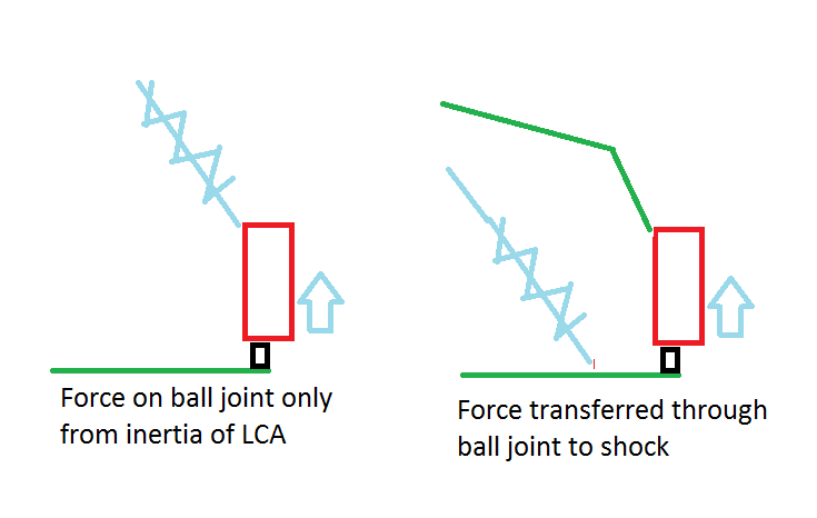
The failure force ranged between 43 and 45 kilonewtons, which is a range of 9666 pounds to 10116 pounds. With 350 pound/inch springs that means you'd have to compress the springs by 27 inches to generate enough force to pull the ball out of the housing.
That's a lot more travel than the 818 suspension has, so as long as you don't bottom out, the joint probably won't fail.
On the other hand, it would be nice to have a margin of safety. If you go with a factor of three, then compressing the springs by 9 inches reaches a conservative upper limit. That would still bottom out the the 818. But considering that bottoming out would put a lot more force on the joint than the spring does, I'd be a little worried that it wouldn't take too many potholes to bust a ball joint.
I assume the strength of the joints probably decreases with age and wear. So at the very least, I think I'll order a new set of quality joints before I hit the road.
I don't know the stiffness of the 818R springs. I'm sure they are a lot stiffer, which would put a lot more stress on the joints for a given compression, but hopefully they will spend most of their time on smooth tracks where they won't likely bottom out.


 Thanks:
  Likes:


 Reply With Quote