Visit our community sponsor

Thanks:
29

Likes:
38
-
Senior Member

Panel Mockup Complete
It’s been a while since I’ve posted any updates. I’ve been working but pretty routine stuff and not too photogenic. But I’ve now completed most of the panel fitting, drilling and mockup. Thought I’d go ahead and post. This is all about to come back apart and I’ll be taking most of the raw pieces out for powder coat. Most of the panels will be the same silver/grey as the Anniversary chassis and a few white to match the ones already provided by Factory Five. I’ve changed and/or modified a few, so will get them done to match. I’ve got a few panels permanently mounted, but most are just cleco’d for now.
For the most part, I followed the recommended guidelines of two inch spacing for panel to panel, and three inch spacing for panel to chassis. When over wider chassis members, I did stagger them so they look a little closer. Having some of the panels already powder coated meant taking special care with them to not scratch, mark, etc. I just used a bunch of blue masking tape when laying out holes, drilling, etc. Reinforces the practice to drill and fit before powder coat whenever possible. Few other hints for first time builders: Take the time to lay out the holes straight, evenly spaced, etc. Lots of them are hidden when you’re done. But a lot of them aren’t, and it really makes a difference IMO in the quality look of the final product. Also take the time to think ahead of where you’re going to fit the tool to pull the rivet. Most are wide open. But check before you drill. Don’t put holes where you can’t get a tool on them. Also think about which side you’re going to pull the rivet from. I strongly prefer that any exposed rivet, even underside, in the wheel wells, etc. the head is showing not the crumpled business side. For sure this is the case in the obvious areas like the engine compartment. But in my overly obsessive opinion, I try to do the same everywhere. Just plain looks better and more professional. Finally, while the panels are perfectly cut and mostly fit really well, take your time to get them just right. A bend may need to be adjusted slightly, you may need to trim slightly to clear a weld bead, etc. If it doesn’t seem like it fits though, check the manual and check your work. I didn’t have to do any significant rework to any piece.
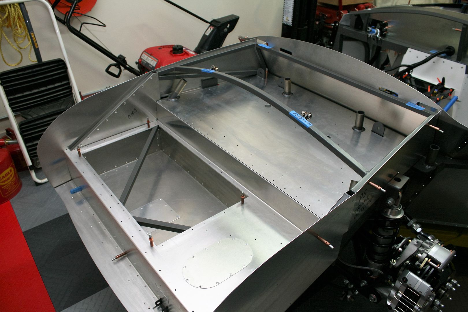
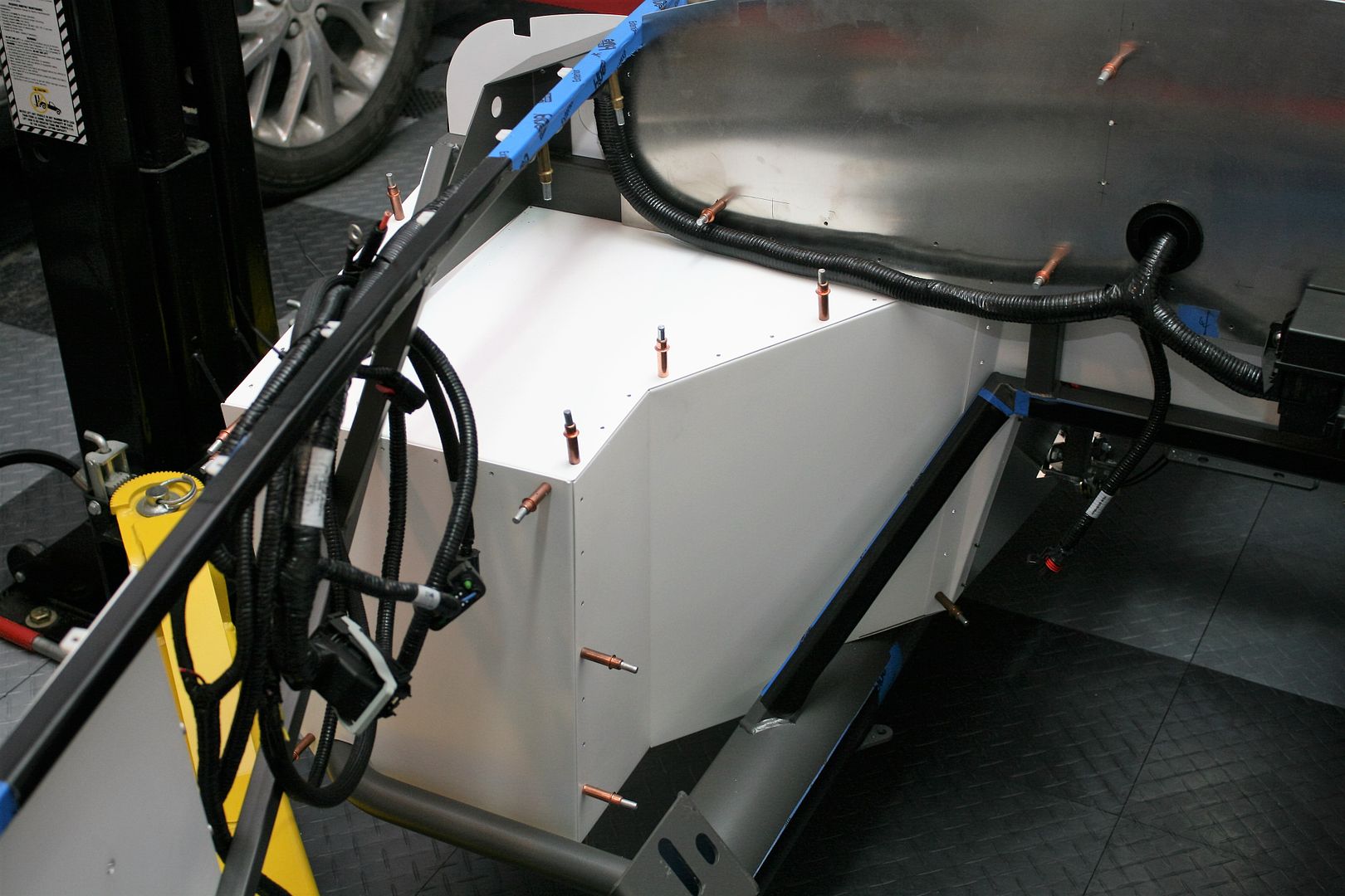
Here are some pics and details. Like I said before, mostly pretty routine stuff. This is the trunk compartment and the Russ Thompson dropped floor. I am leaving in the FF cross braces. Many guys move them below the dropped floor, which is fine. But I don’t weld plus the area will meet my needs with the braces there. Also note I permanently mounted the tank access panels. Probably many won’t agree with this. But I haven’t had to use one of those yet. Plus I played around a little getting the pump assembly out through the access hole. Not easy! It’s hard enough just getting it out of the tank itself. So I just mounted them and will carpet over. With a lift and a floor jack, I can drop the tank in minutes if necessary. For me that was the easier solution. Hopefully I don’t live to regret that decision, but it’s done. I'm also going to quickly make up some fill pieces for the upper side trunk walls. Not necessary, but makes the carpet work much easier and looks good even though not very visible.
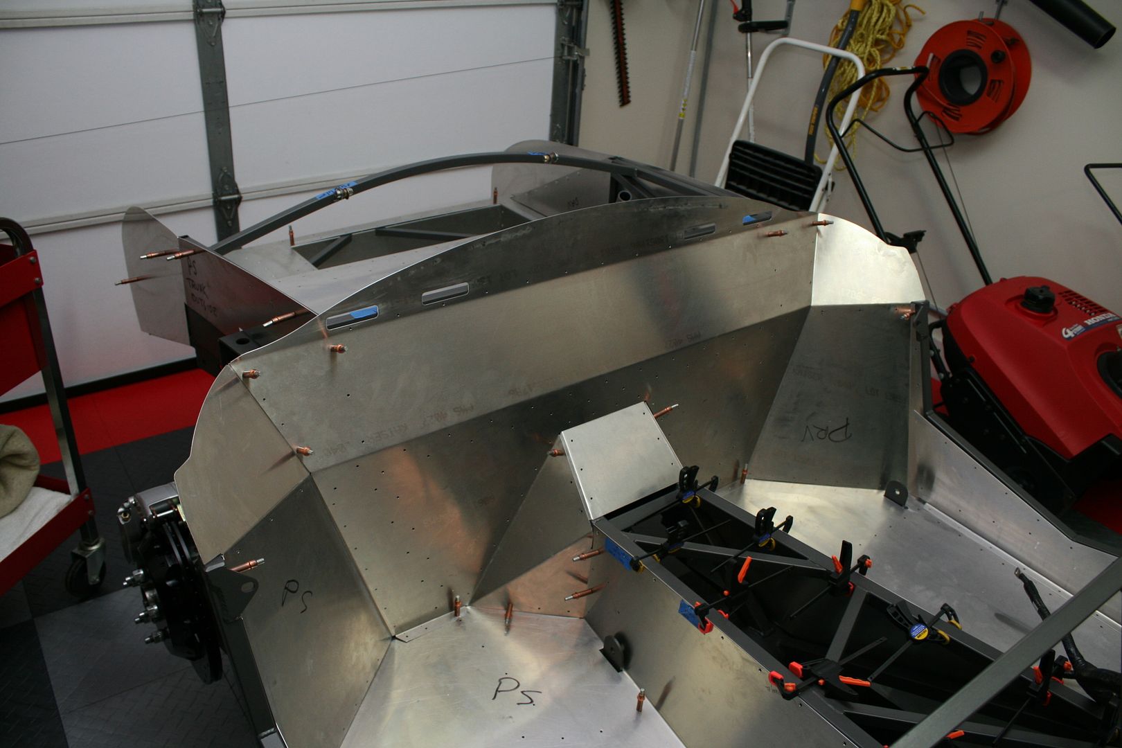
Rear cockpit wall. Nothing too exciting here. I did find the corner tunnel pieces fit better this time than my last Mk4. Maybe something changed, or maybe I just did it right this time. Installing them with the overlaps exactly as in the build manual makes a big difference. Also, just a reminder, install all the trunk panels before installing the rear cockpit wall. Otherwise you’re not going to have too much fun with the rivets along the back edge of the trunk floor and sides.
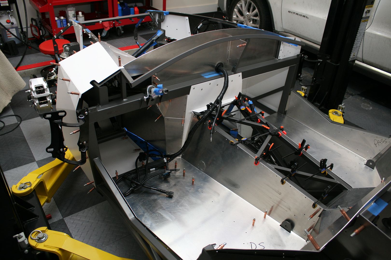
Driver’s side footbox. Again, nothing too exciting. I’m going to do a removable trans tunnel cover. Lots of discussion about whether this is really necessary, and I’ve never done one before or found it necessary. But I’m planning to cover it with something other than carpet. So it just makes sense to go ahead and make it removable. As a result, I drilled for rivets along the top edge. They’ll be flush mounts so the cover can slide past them.
Passenger side footbox from the engine compartment. These are the Factory Five provided white panels. All fit well.
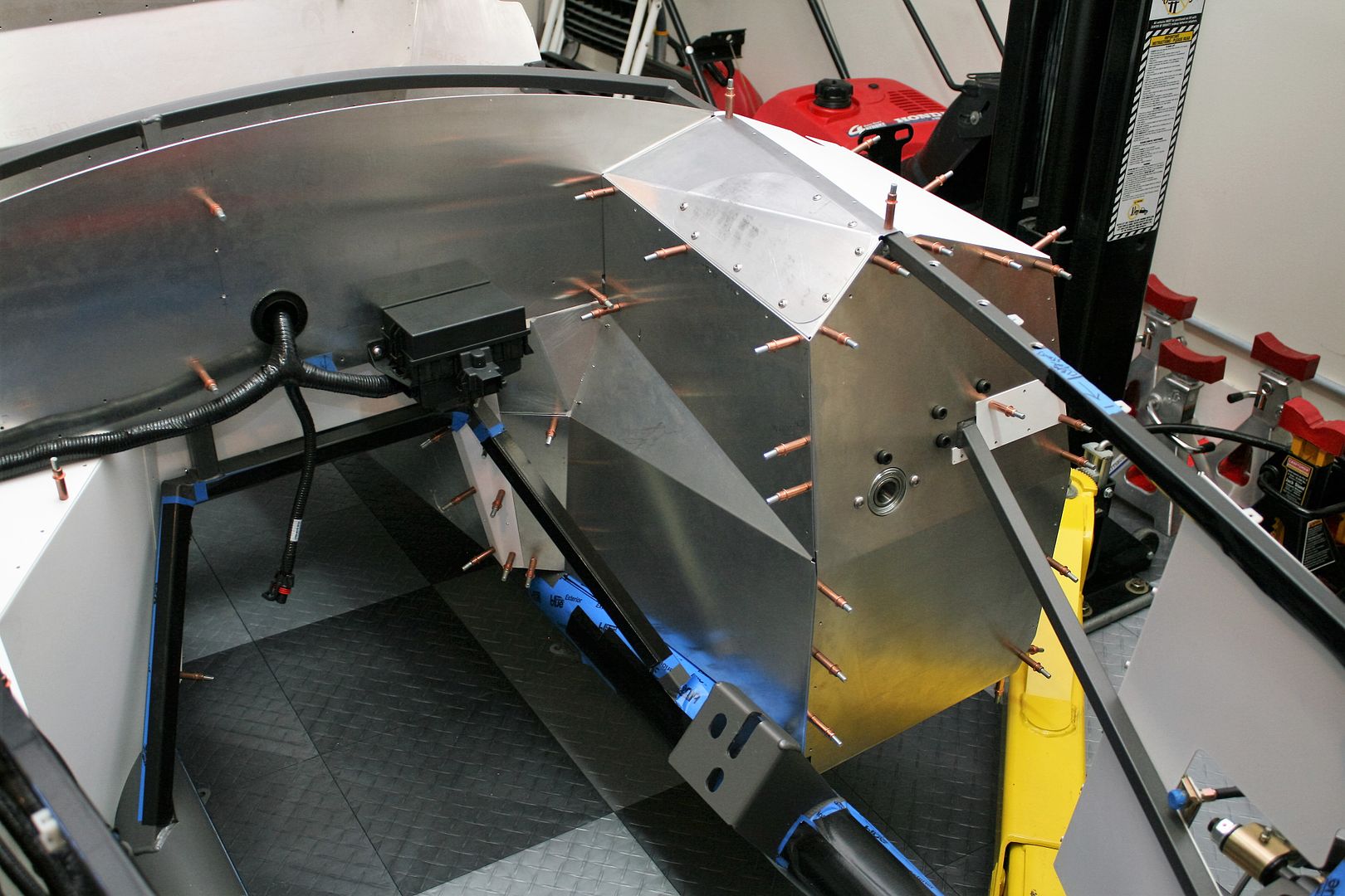
Driver’s side footbox from the engine compartment. Several things here. The inside wall, inside top and cover, and small fill piece are 2bking’s designed Coyote modded panels and supplied to me by another very generous forum member. I mentioned these before. I was able to get them to fit quite nicely. The firewall is also his layout, which I fabbed out of .090 inch aluminum. The front panel is also a piece I made. Factory Five powder coated the Mustang footbox panel instead of the Wilwood footbox panel, which a couple other Anniversary kit buyers also found. Upon further review, I found that if I made a couple minor tweaks to the front panel, the other modded panels fit a little better. That was all the excuse I needed. So I made a new one, and without the clutch or wire harness holes, and also shrunk down the steering column hole since I have the bearing mounted on the inside. Looks nice and clean. A lot of messing around for something that is basically unseen once the build is done. But I like it. I’ll need to punch a couple holes for the front harness and brake lines when the time comes and I determine the exact locations.
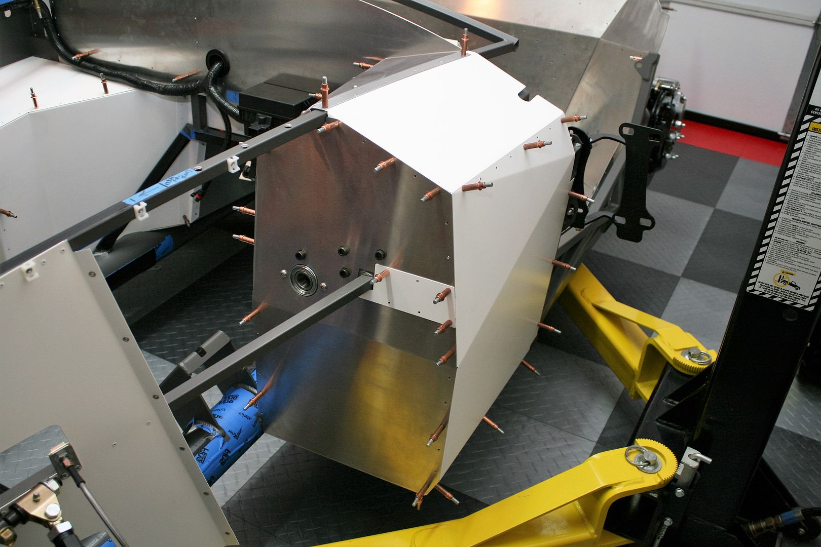
Driver’s side footbox from the outside. The outside side and top are set to go, but I won’t mount them permanently until everything else is done. Basically right before the body is finally installed.
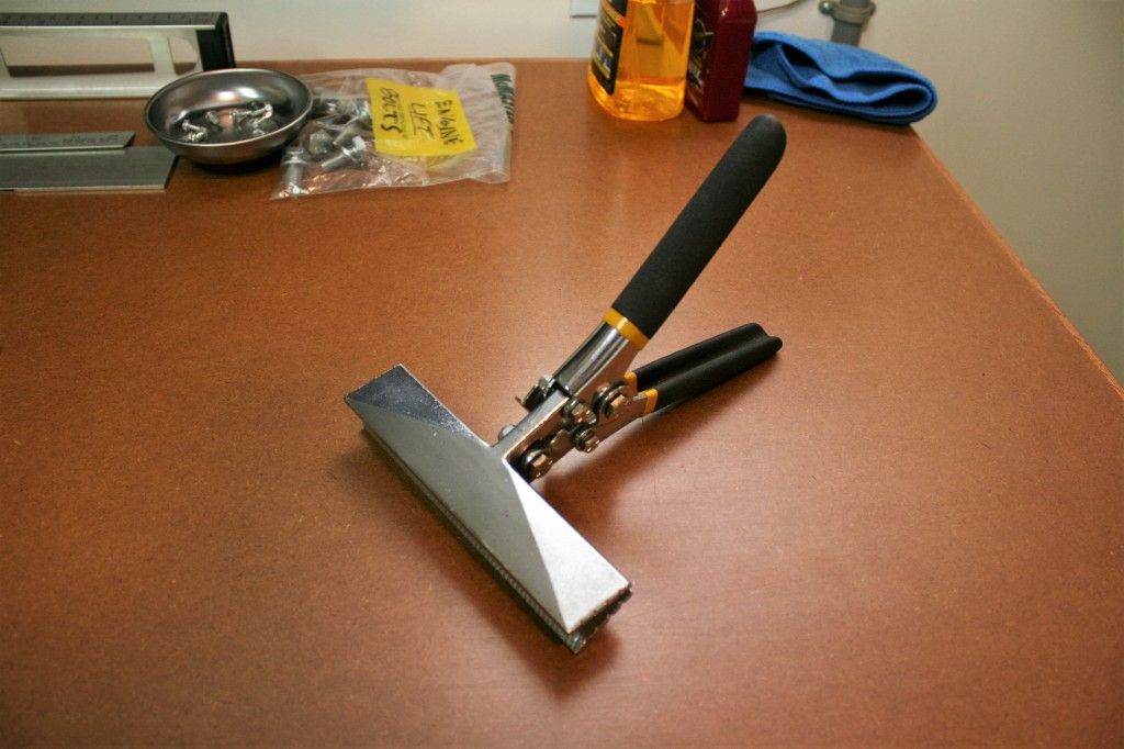
One more tip. If you don’t own this tool from Harbor Freight, I would suggest getting one. Best $15 dollars you’ll spend. Works really great to adjust panels and bends as needed. Their item #98728.
Once I get all the parts to the coater, I’m going to start electrical, fuel lines, and brake lines. First up I think will be the instrument panel. So I’ll get that covered, the gauges installed, and start wiring. Then on from there.
Last edited by edwardb; 01-22-2016 at 07:21 AM.
Build 1: Mk3 Roadster #5125. Sold 11/08/2014.
Build 2: Mk4 Roadster #7750. Sold 04/10/2017.
Build Thread
Build 3: Mk4 Roadster 20th Anniversary #8674. Sold 09/07/2020.
Build Thread and
Video.
Build 4: Gen 3 Type 65 Coupe #59. Gen 3 Coyote. Legal 03/04/2020.
Build Thread and
Video
Build 5: 35 Hot Rod Truck #138. LS3 and 4L65E auto. Rcvd 01/05/2021. Legal 04/20/2023.
Build Thread. Sold 11/9/2023.
-
Senior Member


Originally Posted by
edwardb

Quick question. I see a few people put the the steering pushing on the inside of the driver side pedal box instead of the outside. Any particular reason other than a cleaner look? I see in the manual it shows on the outside. Just curious if it was for power steering or some other reason.
Thanks
-
Senior Member
Originally Posted by
Duke
Quick question. I see a few people put the the steering pushing on the inside of the driver side pedal box instead of the outside. Any particular reason other than a cleaner look? I see in the manual it shows on the outside. Just curious if it was for power steering or some other reason.
Thanks
You are correct. The manual shows the lower steering shaft bearing on the outside of the driver's footbox. I tried to put it there but it just didn't fit due to the fixed length of the lower steering column and the location of the adapter on my PS rack. The only solution was to move it inside. That provided just enough additional space. I never measured or compared, but the steering shaft out of the Breeze Unisteer PS rack looked at bit longer than racks I've used before. I assumed that was the reason, but never took it any further than that.
As a side benefit, it does look a little cleaner on the inside. In this case since I made a new DS footbox front panel, and I already knew the bearing would be on the inside, I just cut a circle instead of the outline of the bearing holder. That makes it look even cleaner. But even for a neat freak like me, that wasn't my motivation for moving it. ")
It doesn't apply to this build, but sometimes it's necessary to move the bearing inside due to vacuum power brakes. The commonly used vacuum booster interferes with the bearing on the outside, and moving it inside is the common solution. You may have seen this on other builds.
Last edited by edwardb; 02-19-2016 at 11:52 PM.
Build 1: Mk3 Roadster #5125. Sold 11/08/2014.
Build 2: Mk4 Roadster #7750. Sold 04/10/2017.
Build Thread
Build 3: Mk4 Roadster 20th Anniversary #8674. Sold 09/07/2020.
Build Thread and
Video.
Build 4: Gen 3 Type 65 Coupe #59. Gen 3 Coyote. Legal 03/04/2020.
Build Thread and
Video
Build 5: 35 Hot Rod Truck #138. LS3 and 4L65E auto. Rcvd 01/05/2021. Legal 04/20/2023.
Build Thread. Sold 11/9/2023.
-
edwardb,
As you mentioned tackling the electrical next, I thought my posing this question may be helpful to others. I'm not certain you would address this as I didnt see it discussed in your previous build. It pertains to the Russ Thomson self canceling directionals mod. I saw in your last build that you used his mod and I plan on using in my current anniversary build. But, as mentioned, I didnt find where you discussed the wiring. I believe he has been selling this unit for some time now, but I'm wondering whether the use of additional diodes, relays and junction boxes, per his electrical schematic are necessary. The complete kit is equipped with a turn signal toggle, a high/low beam toggle and the Ron Francis wiring contains a flasher and relays, etc. So...and this is where I'm automotive electrically challenged...am I not merely swapping one switch for another? Therefore, can I just connect his 5 wires directly to the Ron Francis labeled wiring for those respective features?
-
Senior Member
Originally Posted by
ThickCobra
edwardb,
As you mentioned tackling the electrical next, I thought my posing this question may be helpful to others. I'm not certain you would address this as I didnt see it discussed in your previous build. It pertains to the Russ Thomson self canceling directionals mod. I saw in your last build that you used his mod and I plan on using in my current anniversary build. But, as mentioned, I didnt find where you discussed the wiring. I believe he has been selling this unit for some time now, but I'm wondering whether the use of additional diodes, relays and junction boxes, per his electrical schematic are necessary. The complete kit is equipped with a turn signal toggle, a high/low beam toggle and the Ron Francis wiring contains a flasher and relays, etc. So...and this is where I'm automotive electrically challenged...am I not merely swapping one switch for another? Therefore, can I just connect his 5 wires directly to the Ron Francis labeled wiring for those respective features?
Yes, I'll be starting the wiring very soon, and will post some details I guess. The short answer to your question though is "yes" you can use the Russ Francis turn signal switching as a substitute for the toggle switch shown in the RF schematic, but "no" on the way the RF schematic shows doing the high/low beam switching. The diodes come into play depending on how you want dash indicators to work. Since some of the circuitry between the hazards and turns signals is shared, depending on how you wire the indicator lights, diode(s) may be necessary to prevent backfeeding. They're very simple to add, so don't make decisions about that alone. The pushbutton on the end of the stalk can be whatever you want. Horn, high beams, whatever. It's just a two wire momentary switch. The schematics show a couple of ways to switch high/low beam using this button with a relay. There are also electronic switching options using the button, which is what I'll be doing. This can be a complex subject and there are lots of threads on the subject, mainly on the other forum. Hopefully this helps a little.
Last edited by edwardb; 02-20-2016 at 11:09 AM.
Build 1: Mk3 Roadster #5125. Sold 11/08/2014.
Build 2: Mk4 Roadster #7750. Sold 04/10/2017.
Build Thread
Build 3: Mk4 Roadster 20th Anniversary #8674. Sold 09/07/2020.
Build Thread and
Video.
Build 4: Gen 3 Type 65 Coupe #59. Gen 3 Coyote. Legal 03/04/2020.
Build Thread and
Video
Build 5: 35 Hot Rod Truck #138. LS3 and 4L65E auto. Rcvd 01/05/2021. Legal 04/20/2023.
Build Thread. Sold 11/9/2023.
-


Drivers side footbox from the engine compartment. Several things here. The inside wall, inside top and cover, and small fill piece are 2bkings designed Coyote modded panels and supplied to me by another very generous forum member. I mentioned these before. I was able to get them to fit quite nicely. The firewall is also his layout, which I fabbed out of .090 inch aluminum. The front panel is also a piece I made. Factory Five powder coated the Mustang footbox panel instead of the Wilwood footbox panel, which a couple other Anniversary kit buyers also found. Upon further review, I found that if I made a couple minor tweaks to the front panel, the other modded panels fit a little better. That was all the excuse I needed. So I made a new one, and without the clutch or wire harness holes, and also shrunk down the steering column hole since I have the bearing mounted on the inside. Looks nice and clean. A lot of messing around for something that is basically unseen once the build is done. But I like it. Ill need to punch a couple holes for the front harness and brake lines when the time comes and I determine the exact locations.
I noticed that you added the threaded interest to make the top cover of the DS foot box removable. Did you omit the inserts on the top rear of the cover because they will not be accessible when the body is on?
-Steve
-
Senior Member
Originally Posted by
Straversi
I noticed that you added the threaded interest to make the top cover of the DS foot box removable. Did you omit the inserts on the top rear of the cover because they will not be accessible when the body is on?
-Steve
Yes, the upper rear of the cover isn't quite as accessible once the body is on. I decided it stayed in place and sealed fine without fasteners in that area. I have several thick layers of Lizard Skin on the back side of the cover, masked to fit exactly into the opening. Acts sort of like a gasket. This pic later in the build is a similar view with the body on and the access cover removed. You can see how those would be harder to reach. Not impossible, but I just chose not to put anything there.
Last edited by edwardb; 11-30-2016 at 08:27 AM.
Build 1: Mk3 Roadster #5125. Sold 11/08/2014.
Build 2: Mk4 Roadster #7750. Sold 04/10/2017.
Build Thread
Build 3: Mk4 Roadster 20th Anniversary #8674. Sold 09/07/2020.
Build Thread and
Video.
Build 4: Gen 3 Type 65 Coupe #59. Gen 3 Coyote. Legal 03/04/2020.
Build Thread and
Video
Build 5: 35 Hot Rod Truck #138. LS3 and 4L65E auto. Rcvd 01/05/2021. Legal 04/20/2023.
Build Thread. Sold 11/9/2023.
-
Senior Member
Final Assembly Continues
Marching my way toward the Dec 19 paint date. A lot of the details I’m describing are re-runs from my last builds. Especially #7750. But I’ll post anyway since I know a number are following this thread.
Finished gapping the doors. I’m happy with how they fit except for the driver door front lower corner. Maybe the Mk5 that will finally get that fixed. Been around for at least two Mk’s now. Still have to install the door latches, but moved to the final gap on the hood. Temporarily taped a number of bumpers around the inside edge of the body, using varying thicknesses to get the hood level with the body. After 3-4 times on and off the hinges, marking and trimming each time, I’m happy with how it fits. Nice even gap all around. Also rounded the edge slightly, but didn’t go crazy with it. The profile match of the hood to the body is probably the best of my builds to date. Nice.
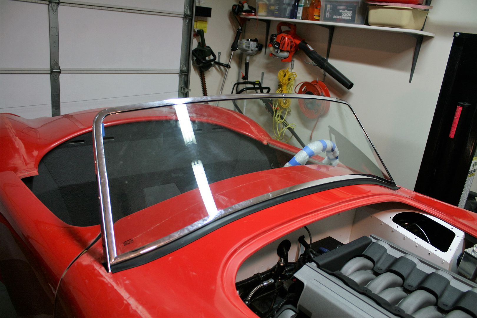
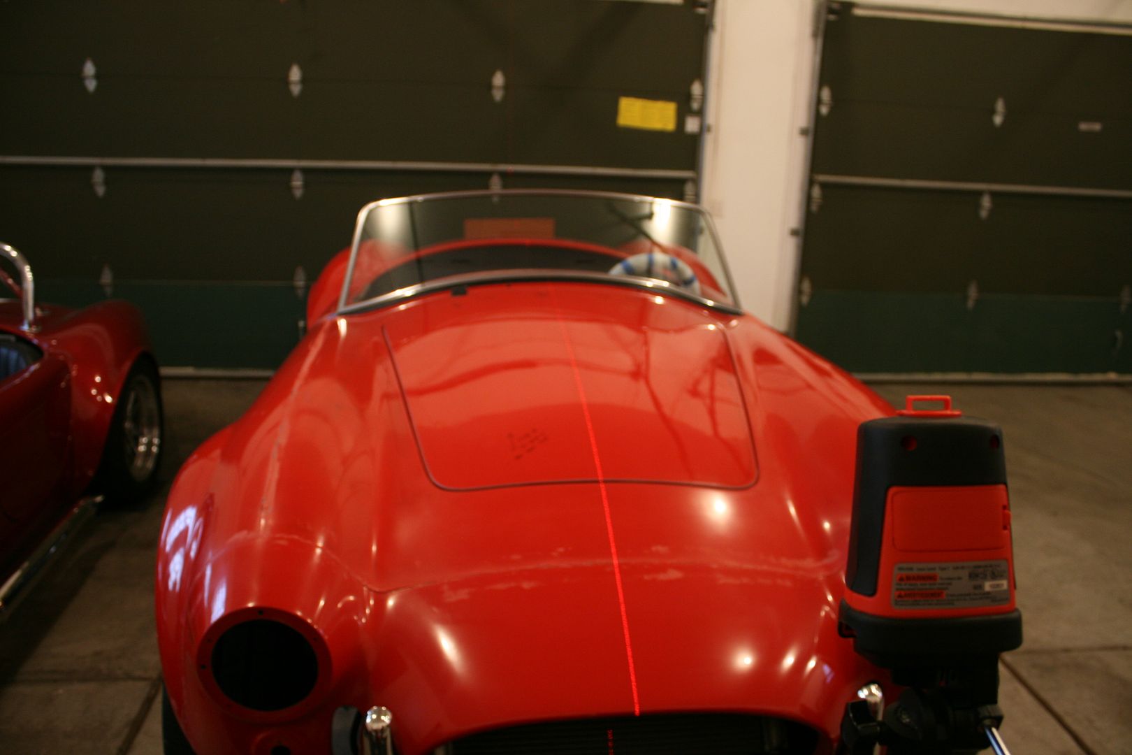
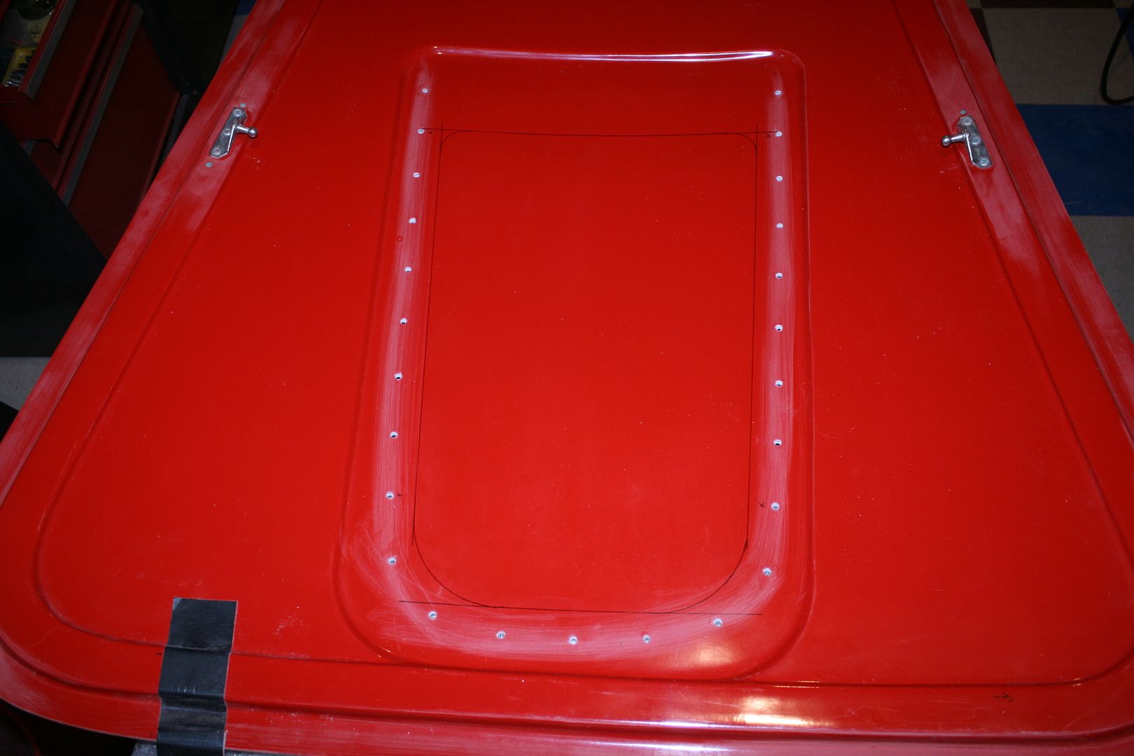
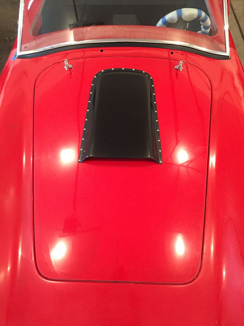
Hood scoop and hood latches were next. I already had the ABS scoop prepped as shown in a previous update. First up is to find the center of the hood and determine the location for the scoop. I like to use a laser level on a tripod. I set it up so it puts down a line from the oil cooler opening all the way over to the trunk lid. Doing this you find the body isn’t completely symmetrical. But with the line across the hood and checking with a tape measure, you can find the best compromise. Since I’ll be doing stripes, it’s even more important to get the scoop in exactly the right place.
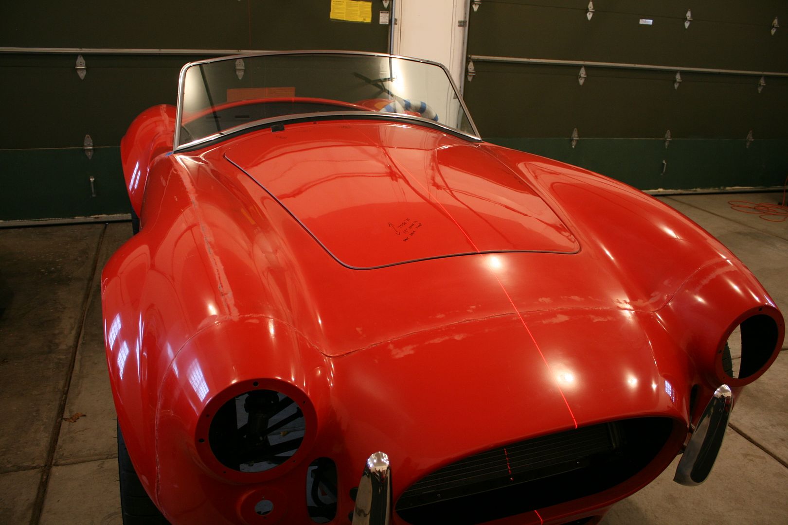
With the centerline on the hood using a Sharpie, now to cut the hole and mount the scoop. Here is where I strongly suggest deviating from the FF instructions. I’ve read several threads where guys have cut the hole in their hood using the provided dimensions and then mounted the scoop. With sometimes bad surprises. Really not good. Instead, find the location for the scoop, drill all the mounting holes. Then use the mounting holes to determine where to cut. Aside from preventing any huge disasters, it looks better IMO to have the underside opening closely follow the outline of the mounting bolts.
First position the scoop the proper distance from the back of the hood, the rear center hole exactly on the hood center line, and the front corners the same exact distance from the center line. These visual cues really come into play with the stripes. Drill the holes a few at a time on each side adding bolts as you go, paying close attention that it’s staying flat and in the right location.
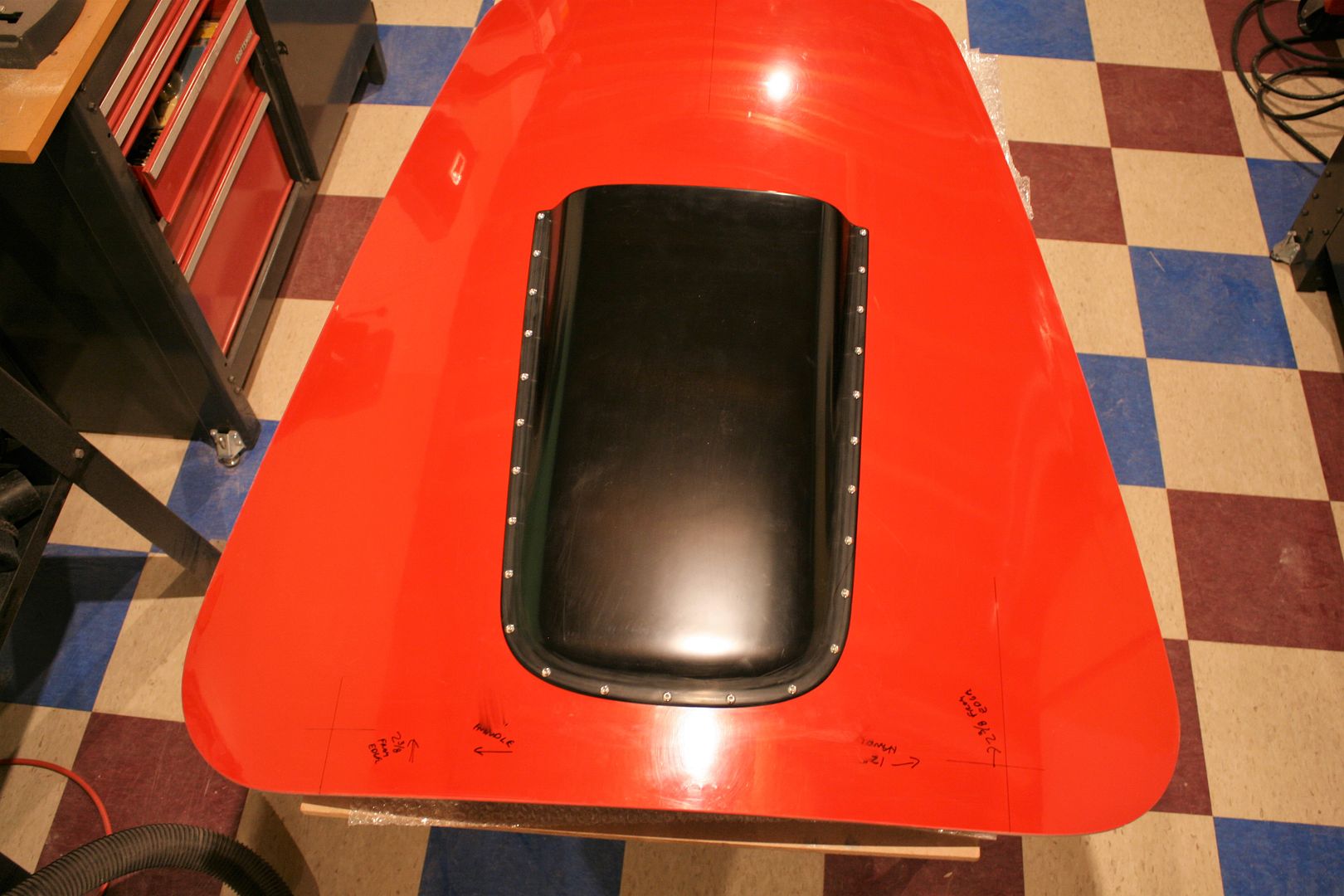
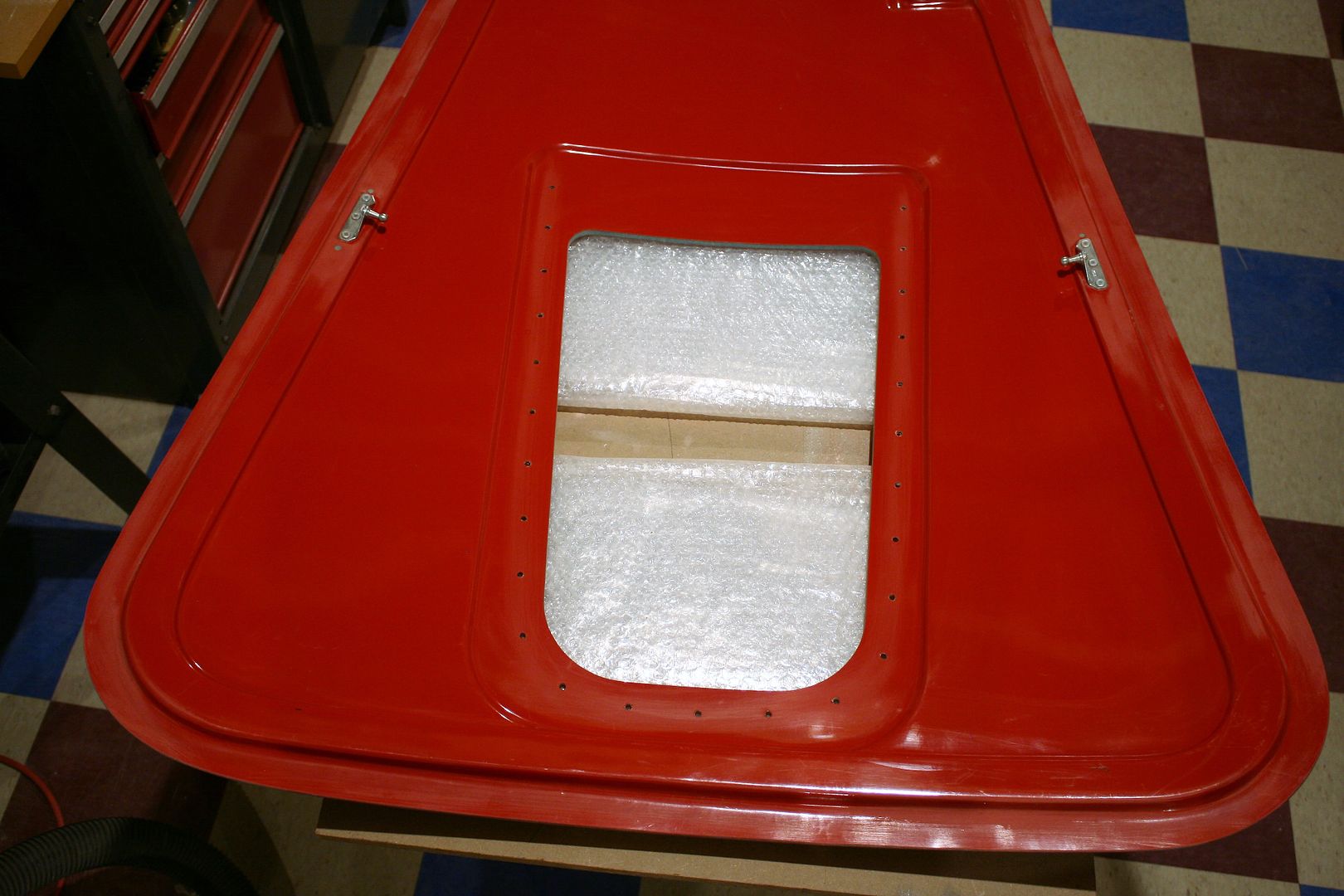
When done, remove the scoop and flip it over. Now lay out the cut based on the hole pattern. I put the cutout about 3/4-inch away from the holes, and roughly followed the curve at the back and a radius on the front corners.
Now cut and trim to the line. The instructions say to use a jig saw. I tried this a bit on my last build and even with the finest and sharpest blade I had, still chipped the gel coat. So switched to a Dremel with a cut-off wheel, which is what I did here. Then cleaned up the edges with drum sanders in my hand drill. Same as a lot of the body work. Once the edges were clean and straight, pushed HSRF down into the gap between the outer and inner hood layers. Took a couple passes to get it clean and straight. Hint: I see some guys using clamps or whatever to pull the top and bottom together. Suggest not doing that. Just let the two sides lay naturally and fill. It’s going to look better without any waves or curves.
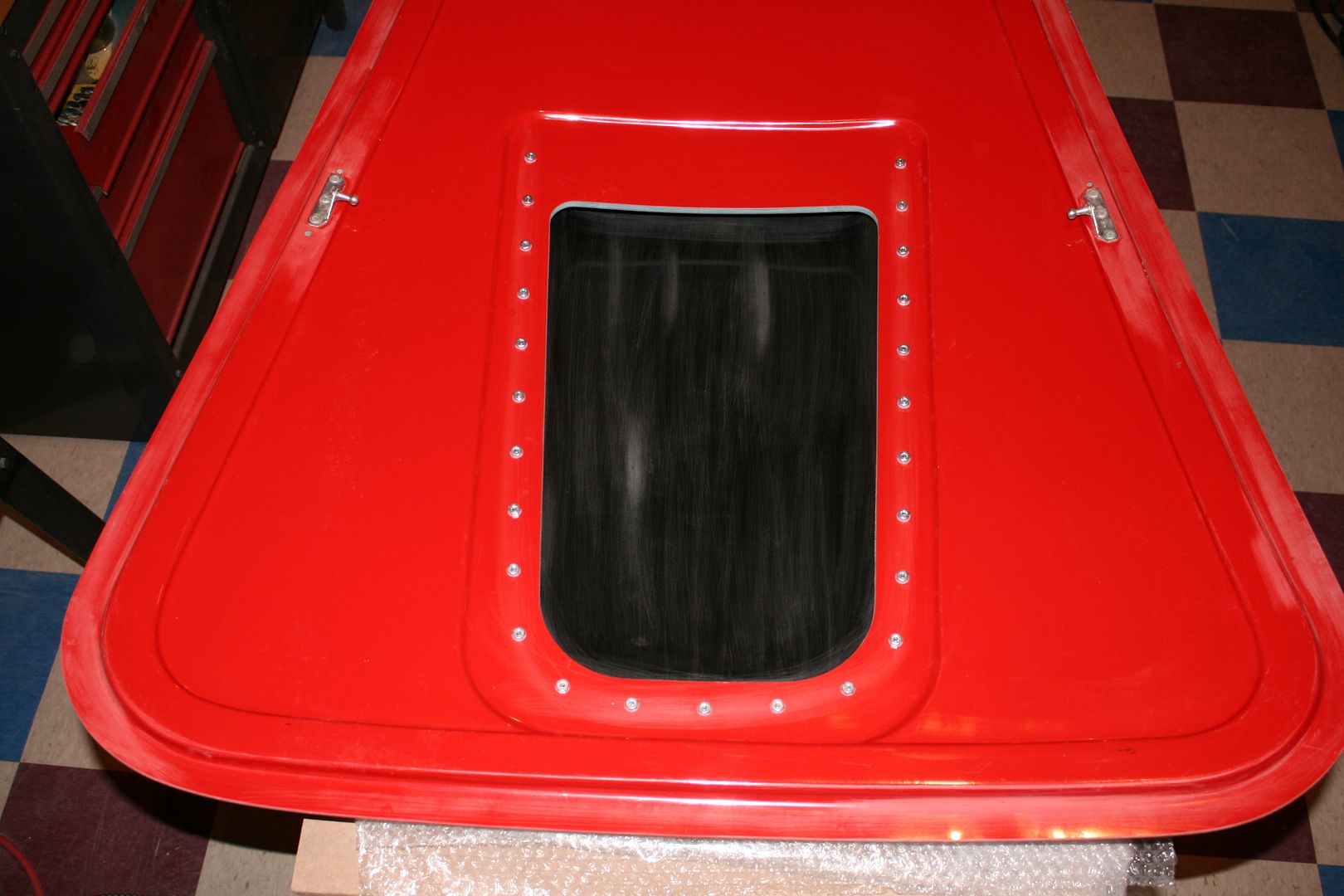
Bolted on the scoop and it’s done for now. I’m using 10-32 SS button head screws like many others and also my last build. Nylon washers on the inside. I’ll replace these regular nuts with SS cap nuts at final assembly.
Last edited by edwardb; 12-03-2016 at 01:57 PM.
Build 1: Mk3 Roadster #5125. Sold 11/08/2014.
Build 2: Mk4 Roadster #7750. Sold 04/10/2017.
Build Thread
Build 3: Mk4 Roadster 20th Anniversary #8674. Sold 09/07/2020.
Build Thread and
Video.
Build 4: Gen 3 Type 65 Coupe #59. Gen 3 Coyote. Legal 03/04/2020.
Build Thread and
Video
Build 5: 35 Hot Rod Truck #138. LS3 and 4L65E auto. Rcvd 01/05/2021. Legal 04/20/2023.
Build Thread. Sold 11/9/2023.
-
Senior Member
Final Assembly Continues (continued)
Next up are the hood latches. I mount them 12 inches each side of the center line. I dont remember what the instructions say. But this dimension is from some build threads a number of years ago. They need to be far enough out to make sure the corner of the hood is pulled down. Im not a fan of the provided self-tapping screws holding the handles into the top layer of the hood. To be honest, Im not a fan of self-tapping screws for much of anything. I always prefer machine bolts into metal threads of some kind. Especially in this case because these handles get lots of use lifting and lowering the hood. Some guys put bolts all the way through with washers and nuts on the back of the hood. Certainly strong enough. But the best location for the handle isnt exactly centered over the rib on the underside, so they end up a little close to one edge. Plus the hardware is exposed. Instead, I like to bond a nut plate underneath the top layer of the hood. These are the same McMaster 98001A125 10-32 nut plates Ive used elsewhere on the build. First cut the necessary holes and slots at the handle locations. Then bond the nut plates with HSRF under the mounting locations. Works really well.
The other thing I like to do with the hood handle is to support where the shaft comes out of the rib on the back of the hood with a bushing, as seen in the above pic. Instead of just having it clear through the raw fiberglass. Does two things. Looks a lot more finished. But more importantly gives cantilever like support to the whole handle assembly and shaft. Noticeably improves how the handle feels with no wobble. To install, I had the handles bolted in place with a clearance hole on the back side. Then put a little HSRF on the flange of the bushings and pushed into place over the latch shaft. When the HSRF set, removed the handles and added more HSRF in the inside. They're not going anywhere and line up perfectly. This is how it looks on the inside of the hood. Will get painted over and look nice and clean.
The hood is done and back on the car.
A little more work to install the brackets for the catches on the hood opening. Then the trunk lid.
Build 1: Mk3 Roadster #5125. Sold 11/08/2014.
Build 2: Mk4 Roadster #7750. Sold 04/10/2017.
Build Thread
Build 3: Mk4 Roadster 20th Anniversary #8674. Sold 09/07/2020.
Build Thread and
Video.
Build 4: Gen 3 Type 65 Coupe #59. Gen 3 Coyote. Legal 03/04/2020.
Build Thread and
Video
Build 5: 35 Hot Rod Truck #138. LS3 and 4L65E auto. Rcvd 01/05/2021. Legal 04/20/2023.
Build Thread. Sold 11/9/2023.
-
Senior Member
Another Final Assembly Update
One week until delivery for paint, and just a few things left on my list. I have the hood, trunk, and doors now officially done and fitted. Good thing. It’s been too cold outside so I’ve been doing some sanding in the basement and tired of cleaning up the dust. Thankfully that’s now done. I’m happy with how the gaps all turned out and how everything fits. I tried to tighten the gaps just a bit from #7750. Those turned out OK, but figured I could improve on them a little. I set the gaps on the new build unfinished the same as #7750 is finished. Once filled and painted, should be a bit closer and what I am shooting for. I put a pretty large radius on the underside front edges of the doors and trunk lid. This will help to prevent any interference when opening and closing. Not necessary to do anything special on the hood as the geometry of the hinges lifts it out of the opening with room to spare. The build looks like this as of late yesterday:
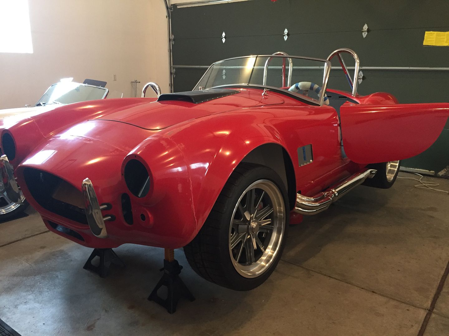
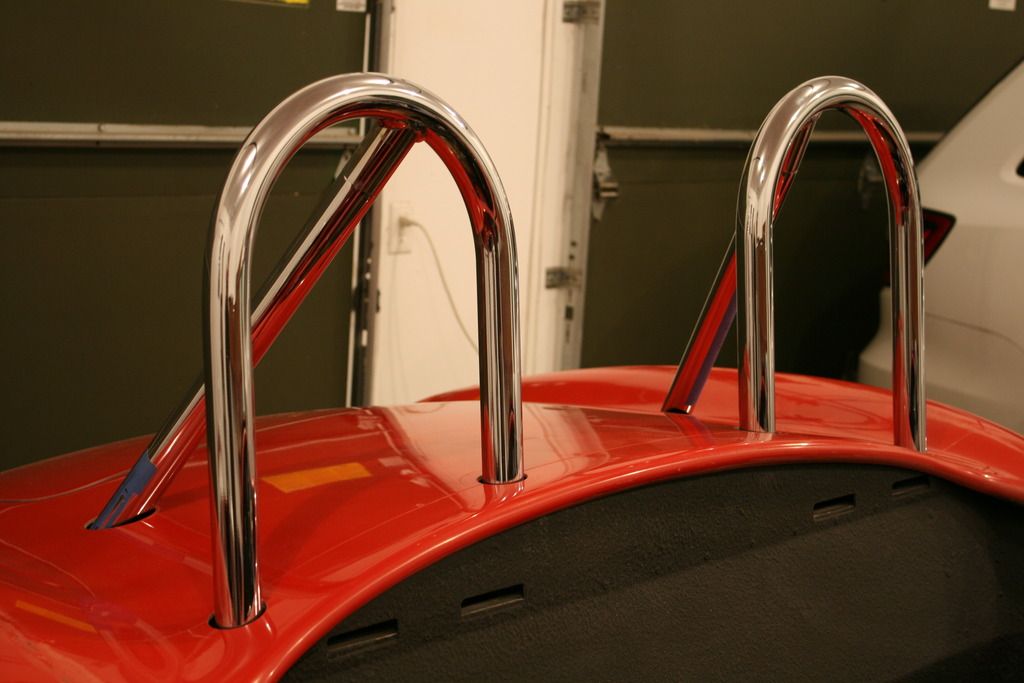
Much of what I’m doing now is pretty routine. But I’ll outline a couple of special things I did. As can be seen in the picture above, I’m going with dual roll bars. Nothing too noteworthy here. These are the chromed Mk4 rolls bars from Factory Five. One came with the kit, the other I added. I know dual roll bars are not faithful to the originals (and some really don’t like them) but caved to the many questions I’ve received in the past about why I don’t care about my passenger. Ok, I do care for my passengers, but that's not the real reason. The real reason is someday I may get enough nerve to do some track time and most places won’t allow an instructor without the second roll bar. They installed pretty easily. The factory cutouts on the DS were pretty close. Just needed a little tweaking. The marks for the PS were in the ballpark, but I just took it slow and easy until they fit through with a little clearance. I’ve got Tangent blind attachments in each. I had previously fit the roll bars to the mounts and got all the holes drilled before mounting the body. Way easier then. Made this final step pretty easy.
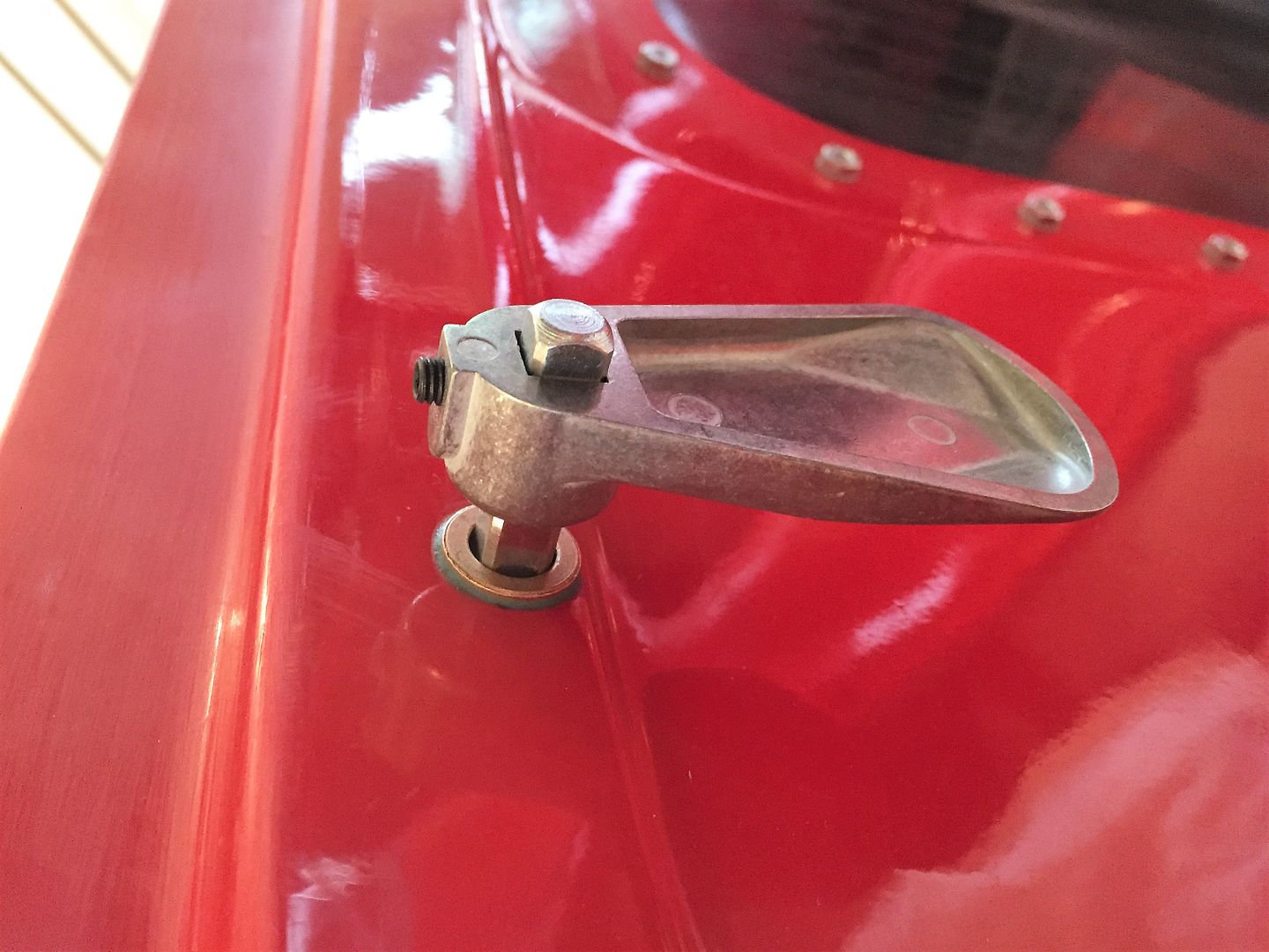
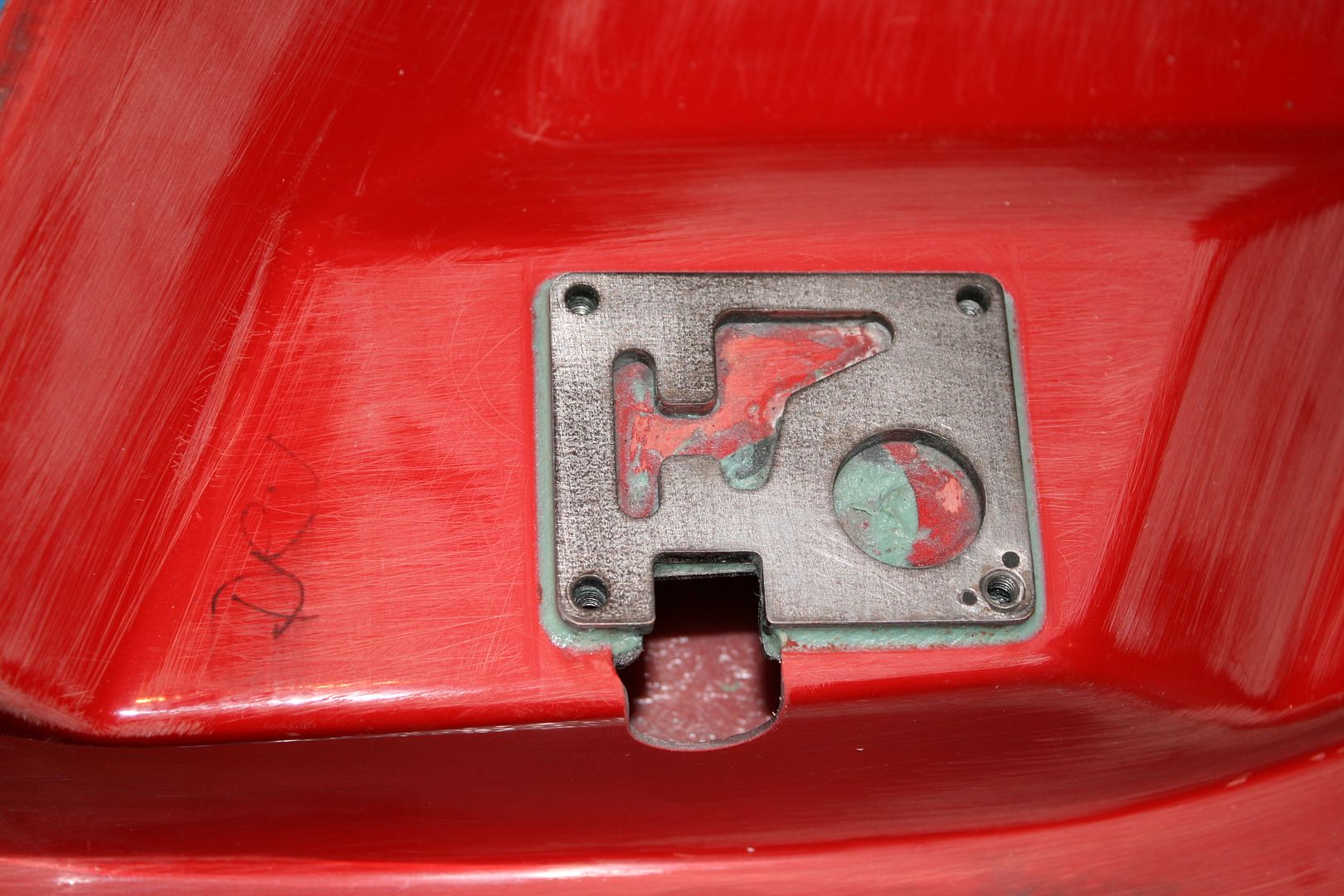
I showed the hood latches in the last update. The remaining step was to add the aluminum catches on the underside of the hood opening. The kit provides a couple of pieces that work OK. But some years ago I saw an idea in another build thread about cutting a profile into the catches that matches the top profile of the hood latch. Gives them a nice snap when they’re turned into place and they stay centered. I’ve done that on each of my builds. Takes a bit larger piece of aluminum angle stock. I used 1 by 1 inch angle, 2 inches long. Mounted them on the underside of the hood opening just behind the inside of the hood opening lip. Then determined where the latch would hit at that point, and cut the profile as pictured. It works really well. Thank you to whoever had that idea. The other thing I do is bolt them on now, burying the head of the bolts in the hood lip with a layer of HSRF. Then the bolts will be hidden when painted.
Next up was the trunk lid. Much like what I already showed with the hood hinge attachments, I like to bond the trunk hinge attachments in place with HSRF and the provided hardware and then paint over. Looks a lot cleaner and more finished. So after fitting the trunk lid and adjusting the hinges, bonded the attachments to the underside of the lid. Note the adjustment of these pieces is only side-to-side. So once they’re in the right location and the lid centered, they don’t need to be adjusted any further. It’s safe to lock them down. The actual hinges allow all the further adjustment necessary. Once bonded in place, I fill the slots with HSRF as well and add a little filet around the edges. Look nice once painted.
Last edited by edwardb; 12-11-2016 at 07:41 AM.
Build 1: Mk3 Roadster #5125. Sold 11/08/2014.
Build 2: Mk4 Roadster #7750. Sold 04/10/2017.
Build Thread
Build 3: Mk4 Roadster 20th Anniversary #8674. Sold 09/07/2020.
Build Thread and
Video.
Build 4: Gen 3 Type 65 Coupe #59. Gen 3 Coyote. Legal 03/04/2020.
Build Thread and
Video
Build 5: 35 Hot Rod Truck #138. LS3 and 4L65E auto. Rcvd 01/05/2021. Legal 04/20/2023.
Build Thread. Sold 11/9/2023.
-
Senior Member
Another Final Assembly Update (continued)
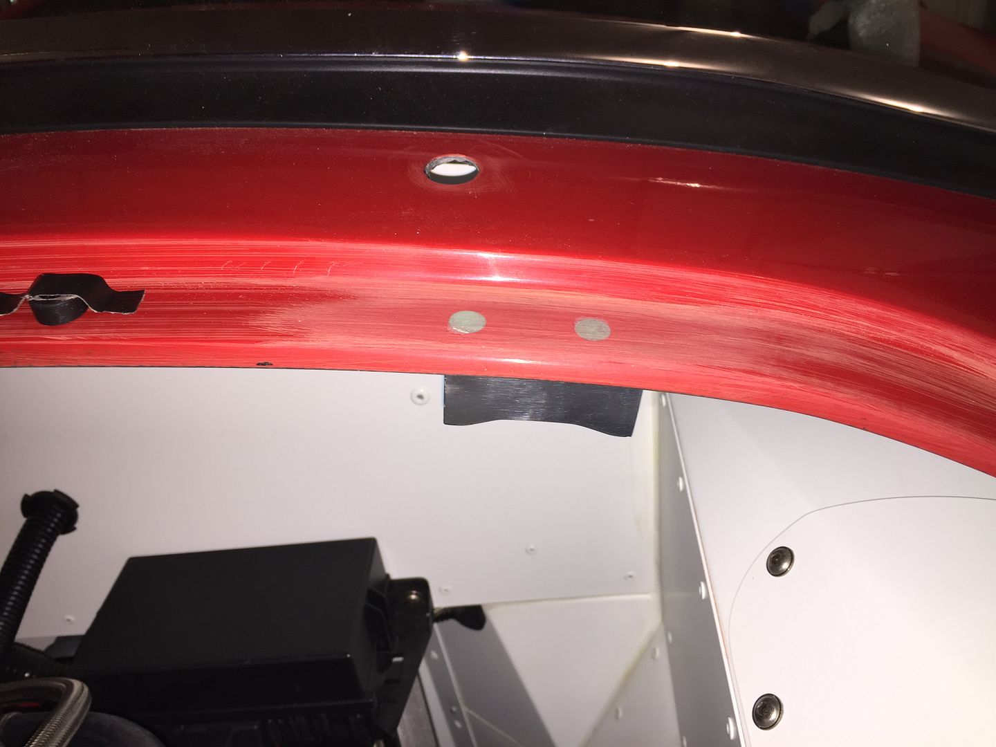
With the trunk lid trimmed and fitted, the hinges installed and adjusted, I installed the handle and catch rod in the stock locations. All worked well and the trunk pulled into the opening perfectly. Nice. Another decision for the trunk lid is some kind of prop rod to hold it open. Well, unless you like dropping it on your fingers or (worse yet) your head. I’ve tried it. Don’t do it. I’ve used Mike Everson’s gas shocks on my last two builds. The Mk3 design with external trunk hinges went between the front trunk opening and the underside of the lid. Those worked well, but took up a little space in the trunk. The Mk4 design with internal trunk hinges presses on the hinges from the rear cockpit wall. Many use these and are very happy with them. But I was never particularly happy with how they work in #7750. They cause the lid to be pushed slightly above the opening, and no matter how low I adjust the hinges, I can't get it quite right. Note that build is a fairly early Mk4 with the round style hinges. Maybe the newer style square hinges in this build would be better. But I decided not to use gas struts and instead went with the old school style latching prop from **********. Found a few threads that described where and how to install, and pretty much followed that. Another option would be a manual prop rod like from Breeze or others, but I wanted something a little more automatic.
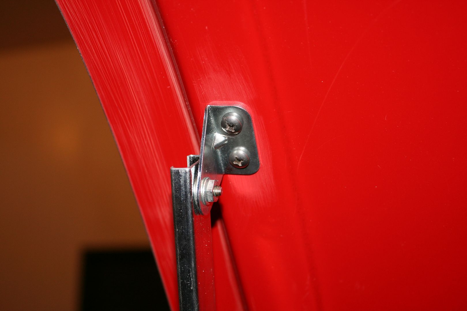
I drilled out the rivet on the lower mounting bracket and put it on the other side so it was oriented toward the trunk lip. I replaced the rivet with a 1/4-inch shoulder bolt from (where else) McMaster. Liked it so much I replaced the rivet on the top bracket as well. I adjusted the angle of the lower bracket a bit until the arm hit the right spot on the lid. The material bends pretty easily in a bench vise. Then bolted the bracket to the lip of the trunk opening. These also are bonded in with HSRF and will get painted over. Note the bumpers taped in place are just temporary. I'll install bulb seal around the trunk opening after paint, fitted around this attachment point.
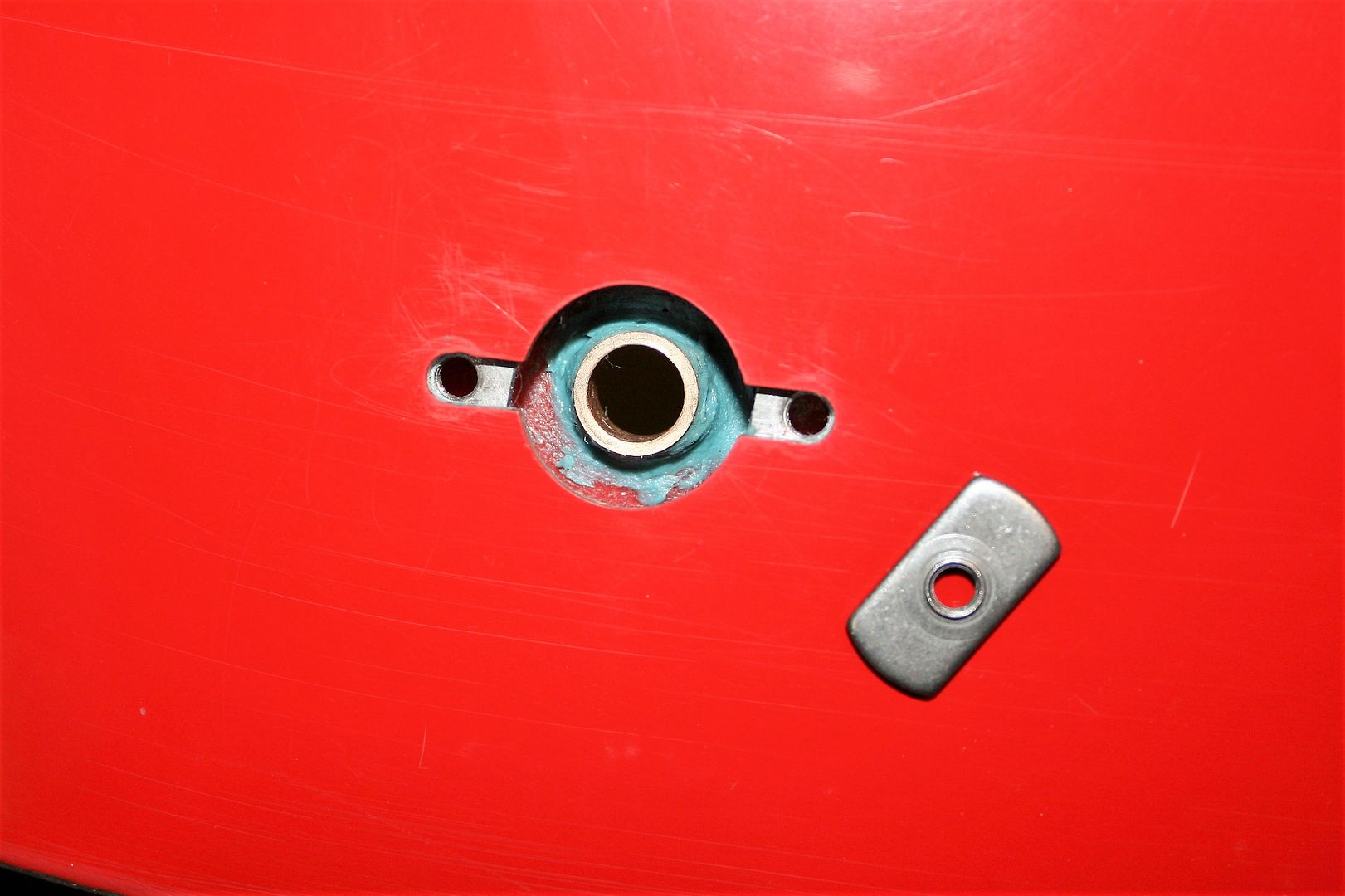
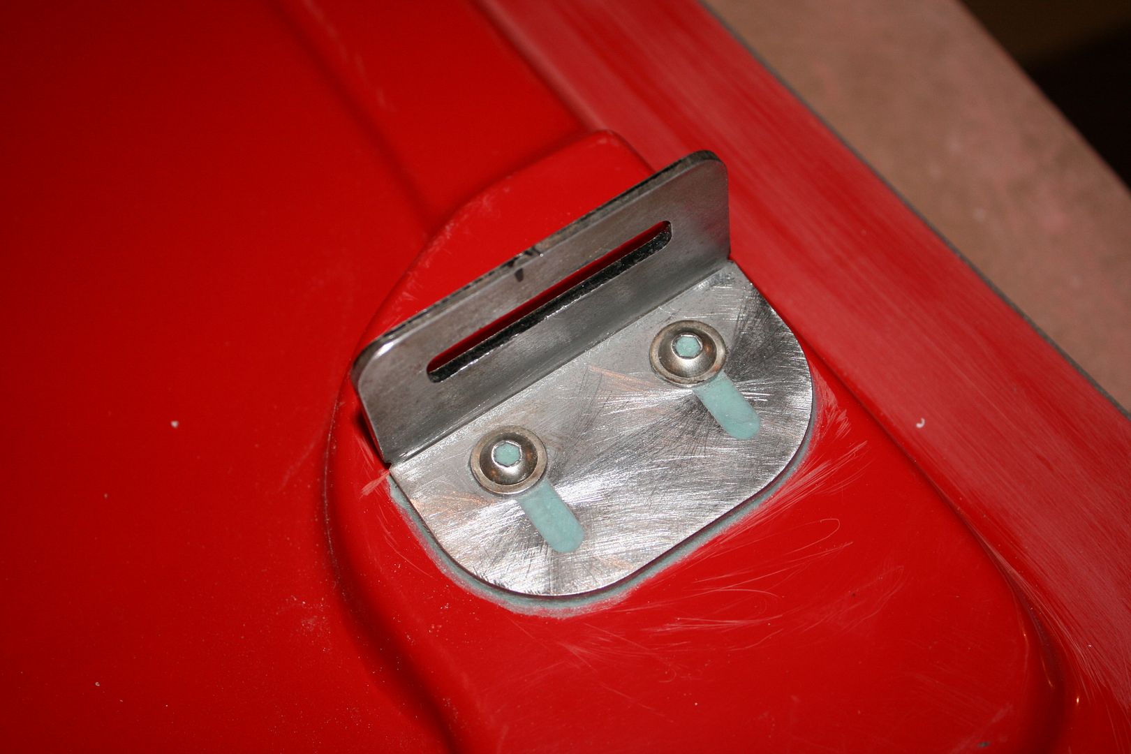
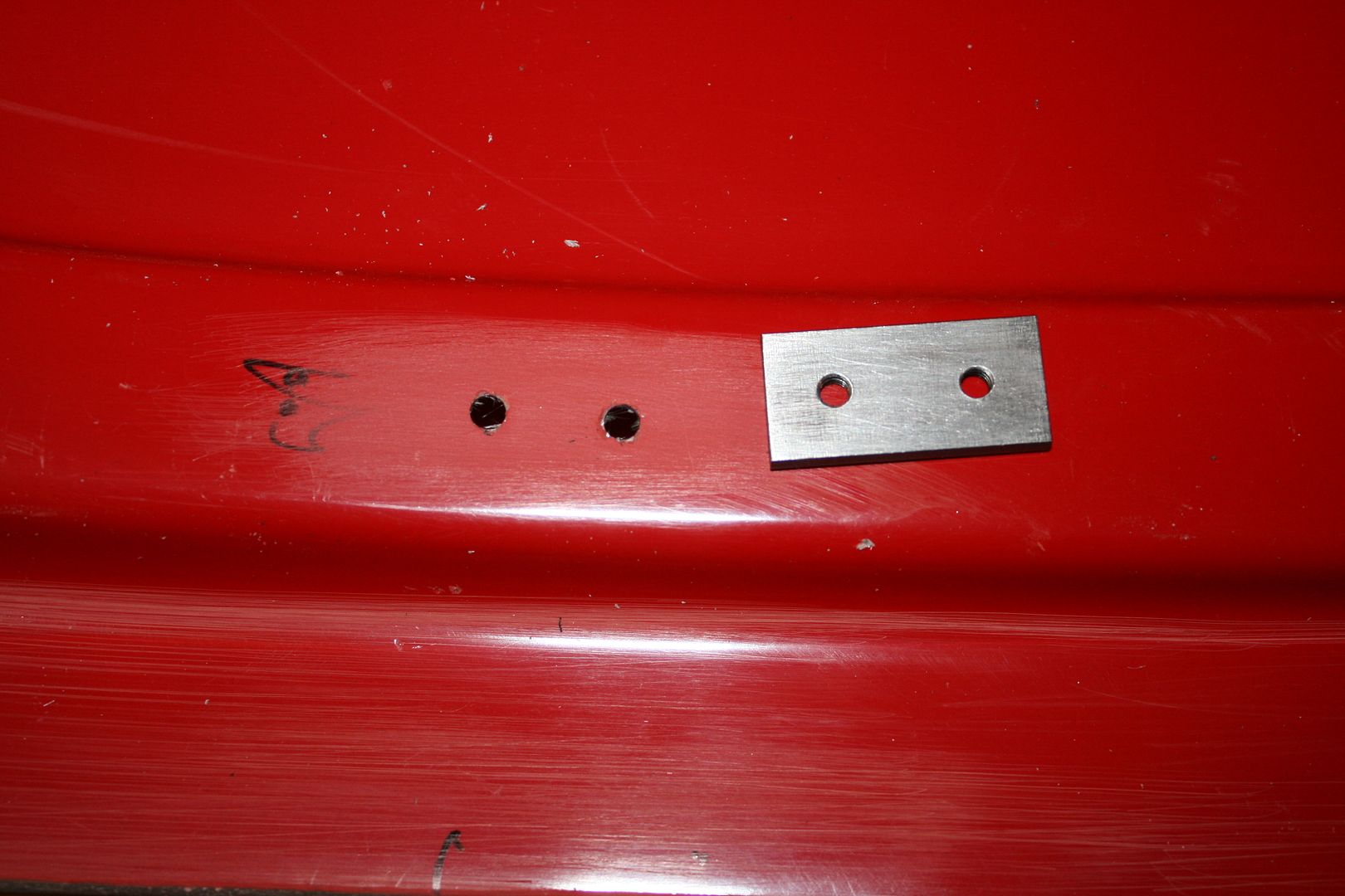
For the attachment point on the lid, I didn’t think just putting self-tapping screws into the lid liner would be strong enough. So I made a little plate from mild steel with two 10-32 tapped holes.
Took a little practicing, but found I could fish it into the right place through the center access hole using a piece of wire and some double back tape. Put some HSRF on it, and put it in place permanently on the underside of the liner. Should be nice and strong.
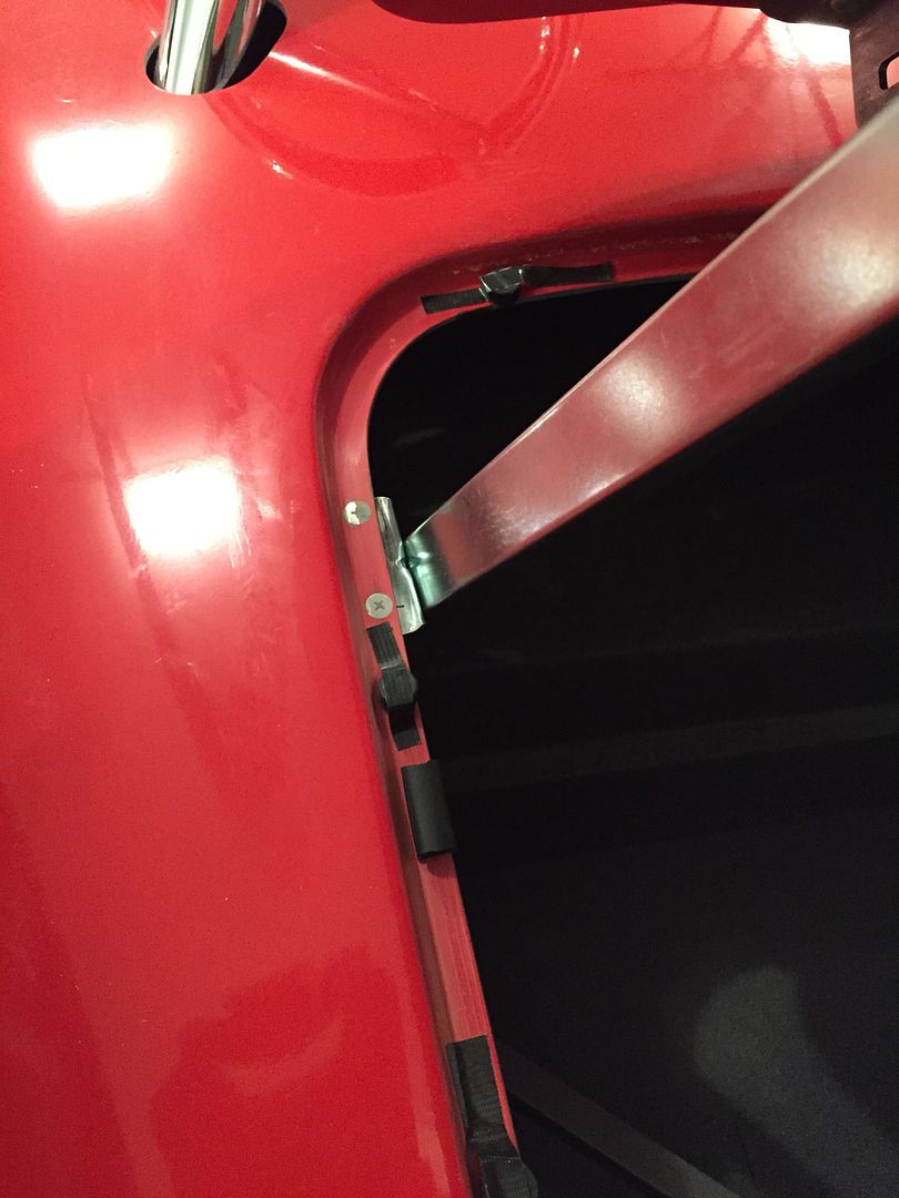
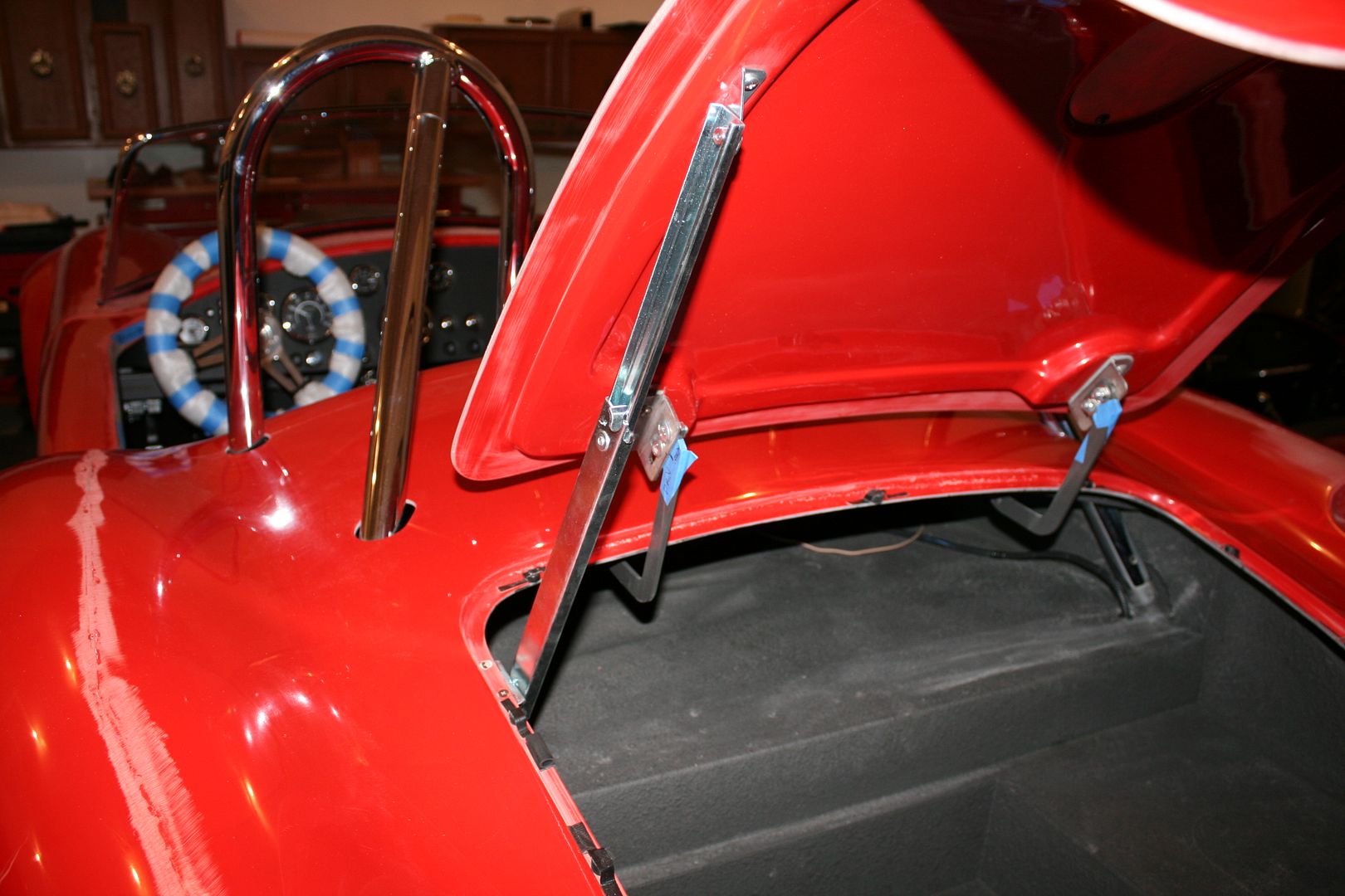
Here’s the prop rod completely installed. I’m happy with how it turned out. It works as expected.
Finally, did the door latches. This is pretty routine. I bonded the spacers to the doors with HSRF. (Catch a theme here?) They too will get painted in place. I installed nutserts in the metal liner that's under the glass skin. So the door latches will be nice and solid. I did the same thing on #7750 and went fine. This time around though on both doors the lower outside hole (RH bottom in this pic) ended up directly over where the underside metal bends and turns down. So I installed a blind mounting nut (or T-nut as we used to call them) on the underside of the spacer. It’s all buried in the HSRF and the spacer isn’t going anywhere with the bond plus the other three through bolts. But added some time to what was supposed to be a simple task.
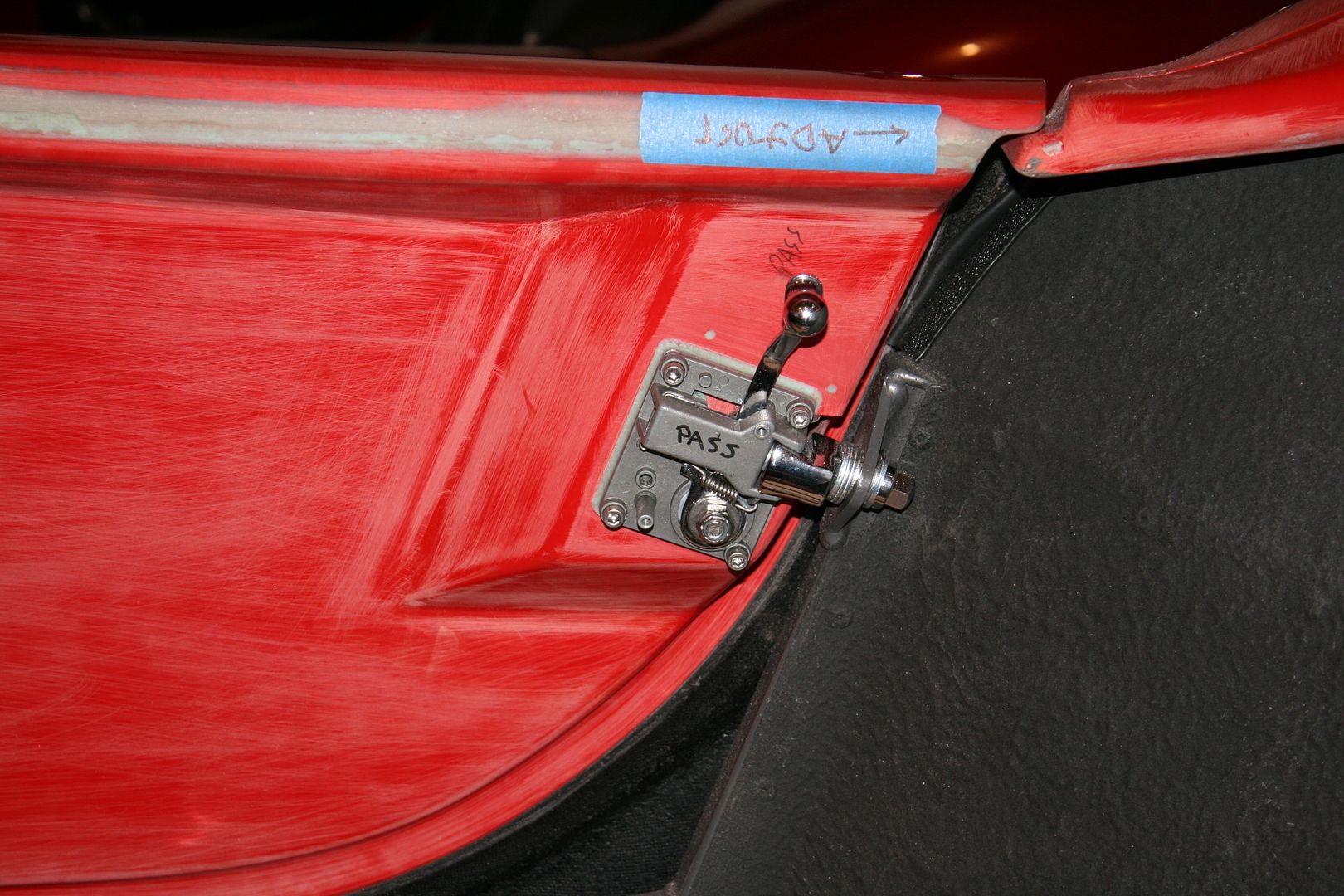
This is one of the door latches installed. I’ll replace the stacked washers with a spacer during final assembly after paint and everything is finally adjusted. I post this picture mainly to pass on a tip about how to easily install these latches. For my first build I really struggled first installing the catch and then trying to align the latch on the door. Then I read on the forum (Jeff Kleiner maybe?) to (1) Clip the latch in the catch, (2) Loosely bolt the catch in the door frame, using washers as needed, (3) Then close the fitted door against the latch base, adjusting the catch until it sits flat in the right location. Mark this location on the door, and attach to the door. Works great.
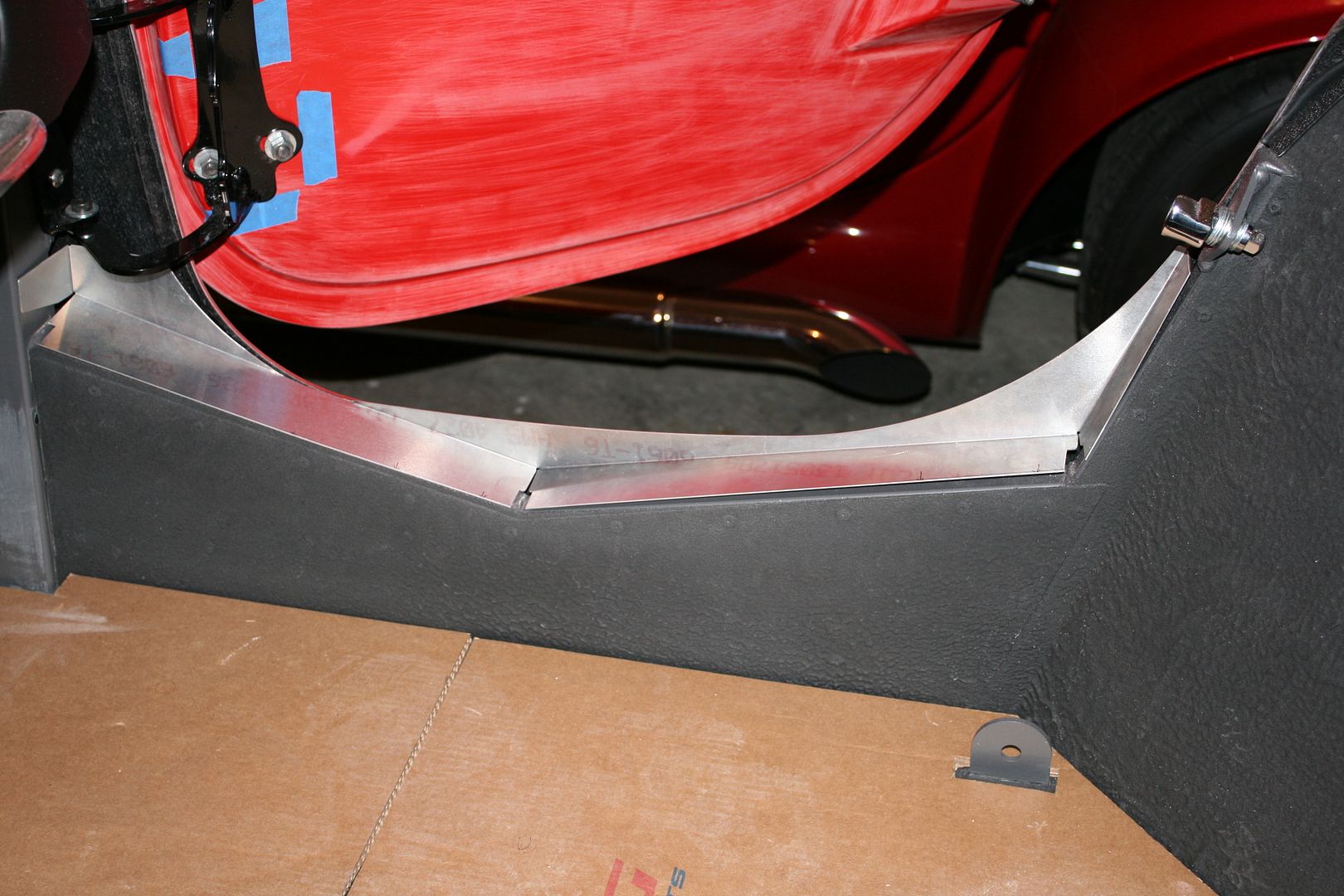
Last picture and again nothing too earthshaking. Here I’m fitting and installing the sill pieces. The significance though is my box of aluminum parts is now officially empty. That’s it. Last pieces.
Today a good buddy dropped over to check out my build, plus see our new place and return some borrowed tools. I hadn’t started the Coyote for quite a few weeks. But of course I had to start it for him. It started instantly like always it seems and sounds great. I’m just so impressed with it, now that I’m past the challenge of getting it installed. Can’t wait to really drive it. On a side note we also found out the CO detector in my garage works as designed. The piercing alarm sound reminded us to open the garage door.
My next update should be dropping the build at the painter. Whoo-hoo!
Last edited by edwardb; 12-11-2016 at 07:48 AM.
Build 1: Mk3 Roadster #5125. Sold 11/08/2014.
Build 2: Mk4 Roadster #7750. Sold 04/10/2017.
Build Thread
Build 3: Mk4 Roadster 20th Anniversary #8674. Sold 09/07/2020.
Build Thread and
Video.
Build 4: Gen 3 Type 65 Coupe #59. Gen 3 Coyote. Legal 03/04/2020.
Build Thread and
Video
Build 5: 35 Hot Rod Truck #138. LS3 and 4L65E auto. Rcvd 01/05/2021. Legal 04/20/2023.
Build Thread. Sold 11/9/2023.
-
Well Used Member

Originally Posted by
edwardb
I showed the hood latches in the last update. The remaining step was to add the aluminum catches on the underside of the hood opening. The kit provides a couple of pieces that work OK. But some years ago I saw an idea in another build thread about cutting a profile into the catches that matches the top profile of the hood latch. Gives them a nice snap when theyre turned into place and they stay centered. Ive done that on each of my builds. Takes a bit larger piece of aluminum angle stock. I used 1 by 1 inch angle, 2 inches long. Mounted them on the underside of the hood opening just behind the inside of the hood opening lip. Then determined where the latch would hit at that point, and cut the profile as pictured. It works really well. Thank you to whoever had that idea. The other thing I do is bolt them on now, burying the head of the bolts in the hood lip with a layer of HSRF. Then the bolts will be hidden when painted.
Question for you Paul. On the hood latch catch bracket, did you HSRF only the machine screws into the body lip, and just bolt on the angle bracket? Or did you HSRF the entire bracket to the underside hood opening lip? The problem I'm running into is it's not really a smooth, 90 degree surface under the opening lip. The Bracket wants to roll under the lip opening. Seems it would be more secure if the bracket was sitting on a better surface, like a fresh bed of HSRF.
If Brute Force doesn't work, you're not using enough of it.
Basic Stuff: MK4 Complete Kit #8439, Wilwood's, 17" Halibrands. Extra Stuff: Stainless brake and fuel lines, Breeze cooling, Battery mount, SS Roll Bar. Old Fart Stuff: Heater, Seat Heaters, Footbox Fresh Air, Stereo, Keyless ignition, Power Steering, Hyd Clutch.
Young & Dumb Stuff: 427w Dart, TKO600, 3 link Moser M9/Ford 9", 3.5:1, Eaton TruTrac Posi. Graduation Thread
-
Member

Drivers side footbox. Again, nothing too exciting. Im going to do a removable trans tunnel cover. Lots of discussion about whether this is really necessary, and Ive never done one before or found it necessary. But Im planning to cover it with something other than carpet. So it just makes sense to go ahead and make it removable. As a result, I drilled for rivets along the top edge. Theyll be flush mounts so the cover can slide past them.
Paul
I am knee deep in fitting panels and noticed that you drilled the top of the floor pans at the trans tunnel. In your post you say that you are doing a removable trans tunnel cover, I will be doing this as well. You also state that you will be using flush mount rivets in that area. Did this work out for you and meet your high standards my friend? Also where did you get the flush mount rivets?
Thanks and have a great day
Jimmy
-
Senior Member
Originally Posted by
Scubasommer
Paul -- I am knee deep in fitting panels and noticed that you drilled the top of the floor pans at the trans tunnel. In your post you say that you are doing a removable trans tunnel cover, I will be doing this as well. You also state that you will be using flush mount rivets in that area. Did this work out for you and meet your high standards my friend? Also where did you get the flush mount rivets?
Thanks and have a great day
Jimmy
Flush rivets worked great there. Not having the head of the rivet above the surface allows the trans cover to fit nicely. I used these from McMaster: https://www.mcmaster.com/97530a097. In addition to the usual drilled rivet holes, a small countersink is also required to let them set flush. These wide range style rivets are nice as well.
Thanks for the compliment and you're welcome. 
Build 1: Mk3 Roadster #5125. Sold 11/08/2014.
Build 2: Mk4 Roadster #7750. Sold 04/10/2017.
Build Thread
Build 3: Mk4 Roadster 20th Anniversary #8674. Sold 09/07/2020.
Build Thread and
Video.
Build 4: Gen 3 Type 65 Coupe #59. Gen 3 Coyote. Legal 03/04/2020.
Build Thread and
Video
Build 5: 35 Hot Rod Truck #138. LS3 and 4L65E auto. Rcvd 01/05/2021. Legal 04/20/2023.
Build Thread. Sold 11/9/2023.
 Posting Permissions
- You may not post new threads
- You may not post replies
- You may not post attachments
- You may not edit your posts
-
Forum Rules

Visit our community sponsor


 Reply With Quote


