Forte's

Visit our community sponsor

Thanks Thanks:  0
Likes Likes:  1
Page 1 of 3 123 LastLast
Results 1 to 40 of 94

Thread: Russ Thompson Turn Signal wiring

Hybrid View

Previous Post Previous Post   Next Post Next Post
  1. #1
    Senior Member Jdav's Avatar
    Join Date
    Sep 2016
    Location
    ATL GA
    Posts
    443
    Post Thanks / Like

    Russ Thompson Turn Signal wiring

    I am wiring up the Russ Thompson Turn Signal and using the momentary stalk button to activate hi beam/low beam & Flash to pass with a Ron Francis harness.
    I've looked through all of the diagrams provided and others I have found, but still unsure. Especially when it comes to what wires are feeding each relay.
    Would appreciate confirmation from you guys that I am doing this right:

    Feed:
    Connect the RF gray TURN FLASHER FD wire to the Russ Thompson common larger Black wire

    Left Turn:
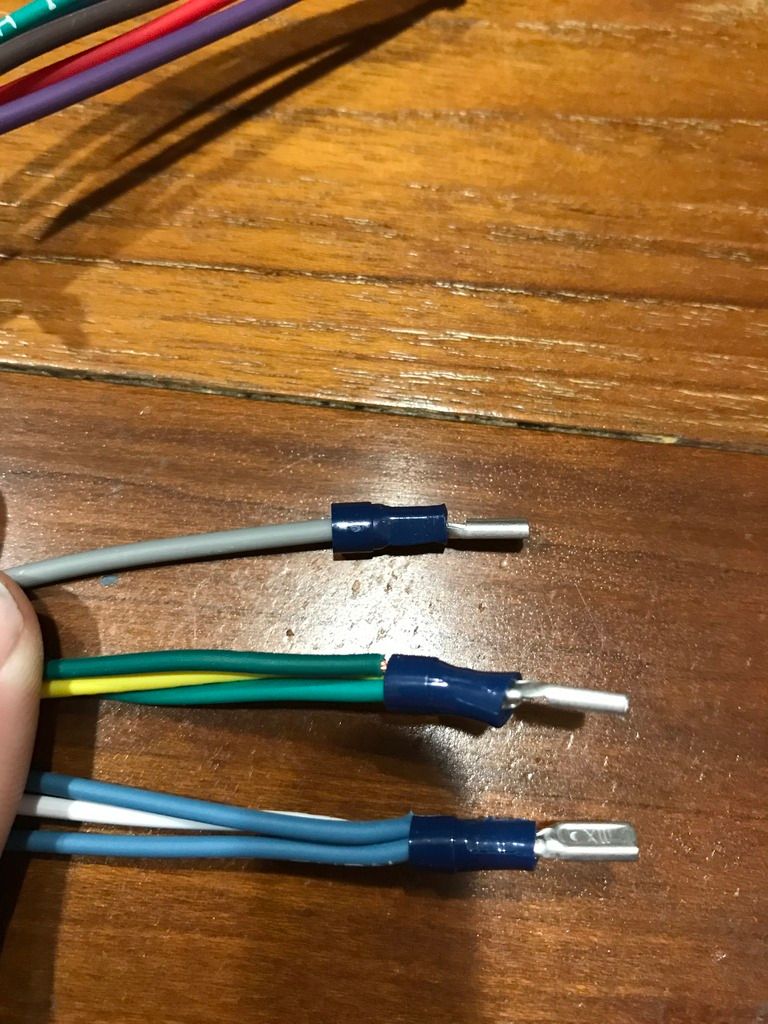
    Connect the RF green/yellow/green (LEFT FRONT TURN/LEFT REAR TURN/LEFT DASH IND LIGHT) bundle to the Russ Thompson Black-white wire

    Right Turn:
    Connect the RF blue/white/blue (RIGHT FRONT TURN/RIGHT REAR TURN/RIGHT DASH IND LIGHT) bundle to the Russ Thompson Black-green wire


    Flasher on/off toggle switch:
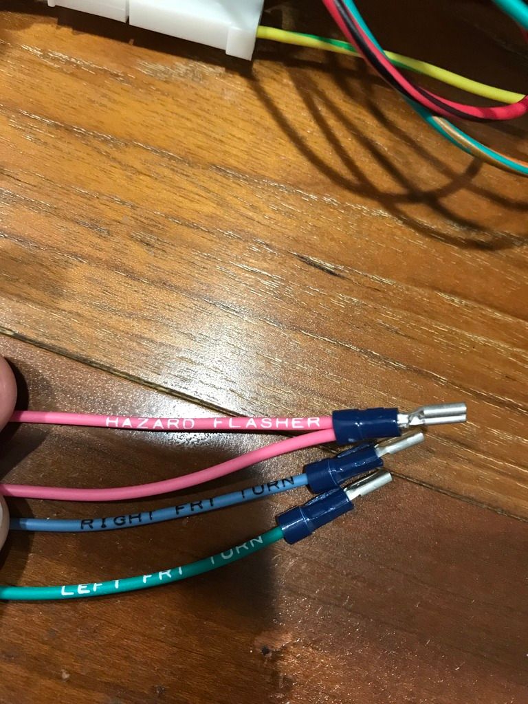
    Connect the RF pink HAZARD FLASHER wire to one spade of the switch
    Add diodes to each then join and connect the RF blue RIGHT FRT TURN and green LEFT FRT TURN wires to the other spade of the switch
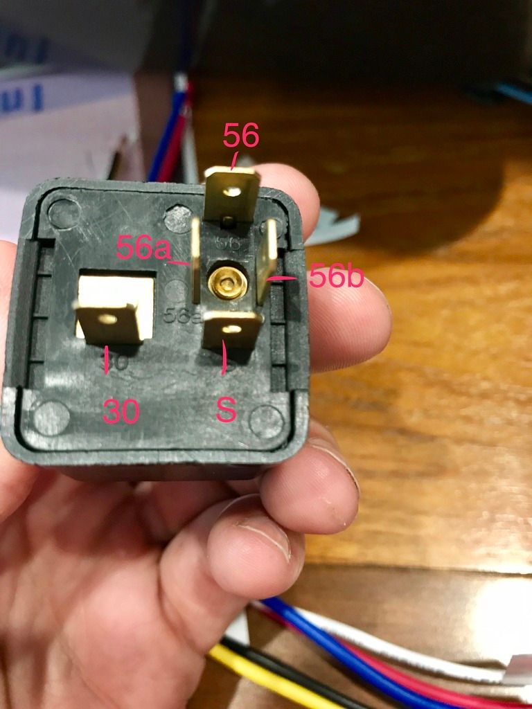

    VW Relay:
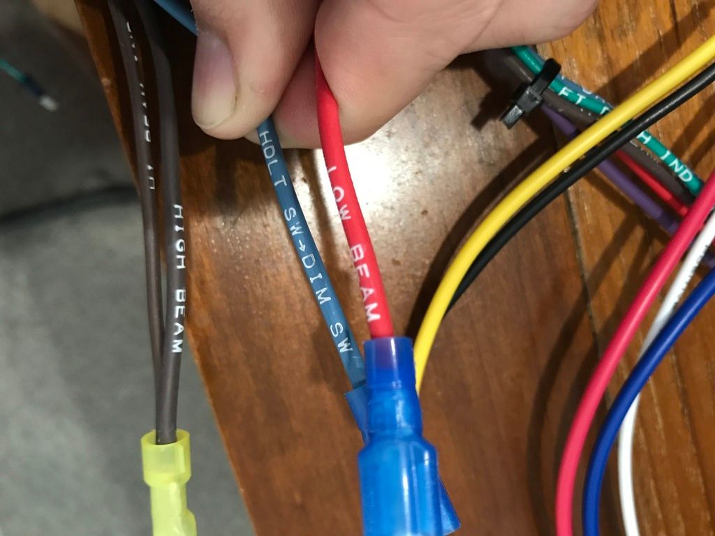
    Split out and connect the RF brown HI BEAM IND wire to 56a
    Connect the RF red LOW BEAM wire to 56b
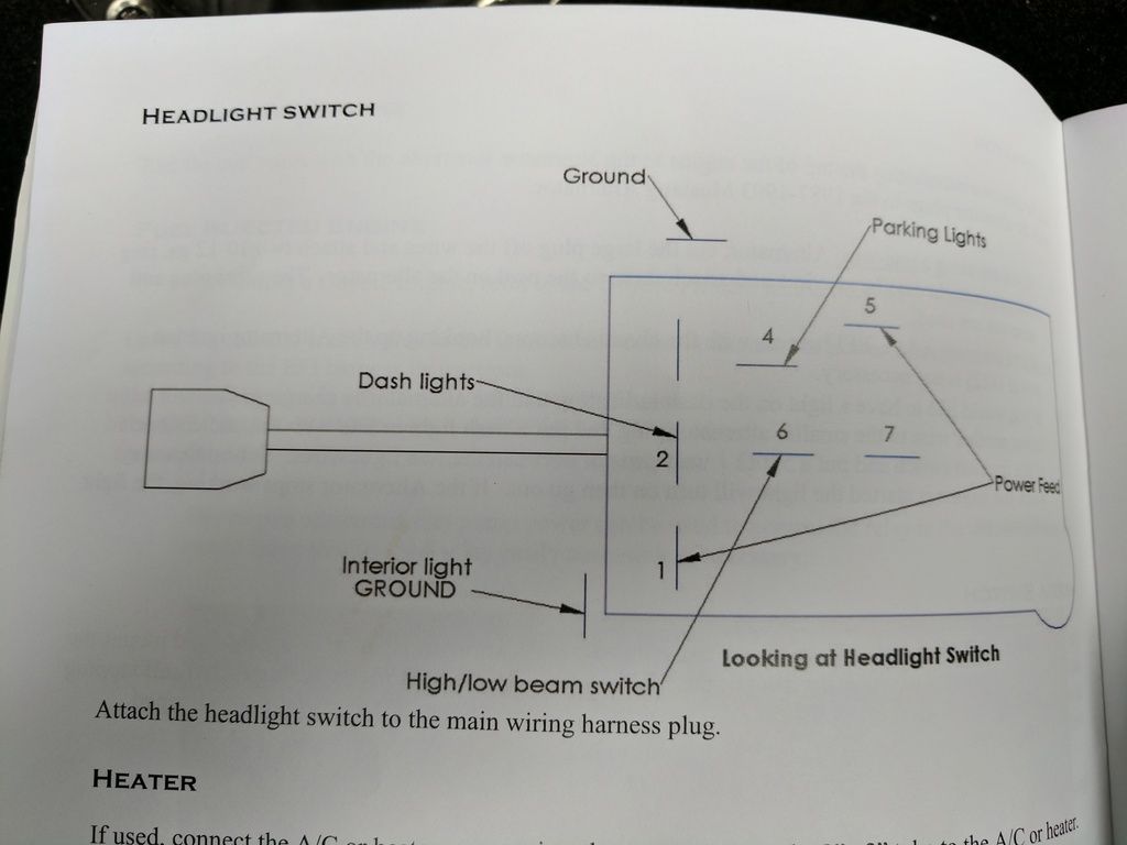
    Connect the RF blue HDLT SW>DIM SW to both 56 and 30
    Run a new wire from S to a diode, merge with a wire from 85 of Bosch relay and connect to one of the Russ Thompson smaller black wires


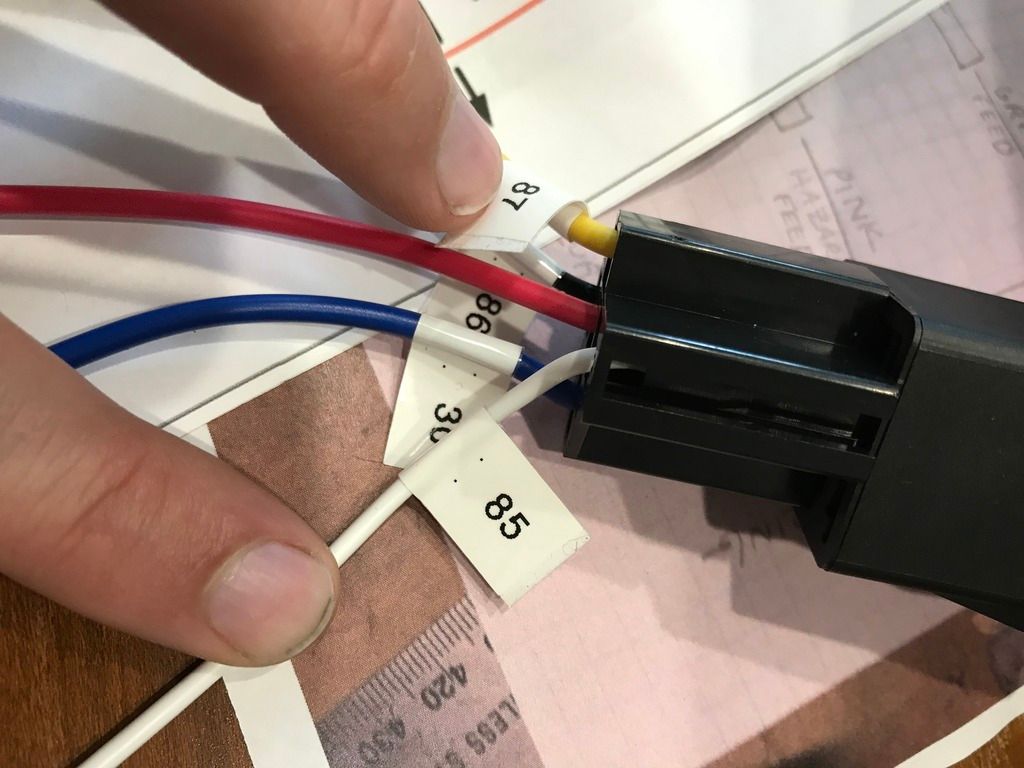
    Bosch Relay (i am also using a relay plug):
    Connect the other split of the RF brown HI BEAM IND wire to 30
    Merge a wire with the one coming from S of the VW relay and connect to one of the Russ Thompson smaller black wires
    Connect RF brown HIGH BEAM wire to both 86 and 87
    87a is not used


    Russ Thompson:
    Ground the other small black wire
    Last edited by Jdav; 05-21-2017 at 10:12 AM.
    MK4 #9028 - Coyote - TKO600
    Delivery: 1/30/17 First Start: 7/23/17 Legal: 10/5/17 Graduated: 10/15/18
    Build thread: http://thefactoryfiveforum.com/showt...8-Build-Thread

  2. #2
    Senior Member NICK C's Avatar
    Join Date
    Jul 2011
    Location
    Lawton, Oklahoma
    Posts
    299
    Post Thanks / Like
    Sounds good to me. I'm in the process myself and am trying to get confident in the procedure. Nick

  3. #3
    Senior Member lahrs37's Avatar
    Join Date
    Jul 2014
    Location
    Philadelphia
    Posts
    377
    Post Thanks / Like
    I am going to lurk as I am doing the same right now and am definitely not sure what I am doing!
    5.0 HO from a '93 Mustang, SVE heads, Trickflow stage 1 cam, Trickflow Street Burner intake manifold, T-5 w/mid shift, IRS
    Delivery 9-10-16, First Start 12-28-16, First Go-Kart 2-18-17
    Build thread: http://thefactoryfiveforum.com/showt...MK4-8951-Build

  4. #4
    Senior Member RickP's Avatar
    Join Date
    Feb 2016
    Location
    Boyertown, PA
    Posts
    683
    Post Thanks / Like
    The RT turn signal wiring can be daunting at first. In fact I wired it once to get it working, then re-wired it to clean it up. Your assumptions are correct. If your wiring a flash to pass and using the FFR supplied headlight switch, use this schematic


    The verbiage on the bottom of the schematic (can't see it in this image) is accurate and addresses your questions exactly.

    I ended up wiring the entire circuit using distribution blocks depicted and just Velcro'd them to the back of the firewall (if you have room). I can't recall exactly what positions the headlight switch needs to be in to operate the flash to pass vs. high beam but the RF harness makes it real easy to wire it. There is a plug that connects from the FR harness to the back of the switch.

  5. #5
    Senior Member Jdav's Avatar
    Join Date
    Sep 2016
    Location
    ATL GA
    Posts
    443
    Post Thanks / Like
    Quote Originally Posted by RickP View Post
    The RT turn signal wiring can be daunting at first. In fact I wired it once to get it working, then re-wired it to clean it up. Your assumptions are correct. If your wiring a flash to pass and using the FFR supplied headlight switch, use this schematic


    The verbiage on the bottom of the schematic (can't see it in this image) is accurate and addresses your questions exactly.

    I ended up wiring the entire circuit using distribution blocks depicted and just Velcro'd them to the back of the firewall (if you have room). I can't recall exactly what positions the headlight switch needs to be in to operate the flash to pass vs. high beam but the RF harness makes it real easy to wire it. There is a plug that connects from the FR harness to the back of the switch.
    Thanks RickP
    I saw that one, but didn't really understand how those distribution blocks were set up. Are the inputs directly across from each other connected but the ones above and below isolated?

    Any strong reason against just using butt connections with heat shrink?
    MK4 #9028 - Coyote - TKO600
    Delivery: 1/30/17 First Start: 7/23/17 Legal: 10/5/17 Graduated: 10/15/18
    Build thread: http://thefactoryfiveforum.com/showt...8-Build-Thread

  6. #6
    Senior Member edwardb's Avatar
    Join Date
    Feb 2011
    Location
    Lake Orion, Michigan
    Posts
    10,577
    Post Thanks / Like
    Quote Originally Posted by Jdav View Post
    I saw that one, but didn't really understand how those distribution blocks were set up. Are the inputs directly across from each other connected but the ones above and below isolated?
    Yes.
    Build 1: Mk3 Roadster #5125. Sold 11/08/2014. Build 2: Mk4 Roadster #7750. Sold 04/10/2017. Build Thread
    Build 3: Mk4 Roadster 20th Anniversary #8674. Sold 09/07/2020. Build Thread and Video. Build 4: Gen 3 Type 65 Coupe #59. Gen 3 Coyote. Legal 03/04/2020. Build Thread and Video
    Build 5: 35 Hot Rod Truck #138. LS3 and 4L65E auto. Rcvd 01/05/2021. Legal 04/20/2023. Build Thread. Sold 11/9/2023.

  7. #7
    Senior Member RickP's Avatar
    Join Date
    Feb 2016
    Location
    Boyertown, PA
    Posts
    683
    Post Thanks / Like
    Quote Originally Posted by Jdav View Post
    Any strong reason against just using butt connections with heat shrink?
    Great debate going on in another thread currently regarding connectors etc. Everyone has an opinion on what's best.

    http://thefactoryfiveforum.com/showt...-advice-please

    For me personally, I did not use any type of butt connector. I soldered those type of connections and heat shrinked them. Just my own personal preference. Del City is a great source (EdwardB turned me on to this source quite some time ago) for any type of electrical component such as heat shrink, terminals, terminal blocks, distribution blocks etc.

    And yes, to echo EdwardB's response to your other question on the terminal block. Whatever you feed going in one side, its the same going out on the other side. The terminals are connected from side to side underneath. With a simple jumper from terminal to another terminal (set), you eliminate the need to splice a wire. If you took the terminal (distribution) blocks out of the schematic RT provides, you would end up splicing a lot of wires together. Not a good way to go and over complicates an already complicated circuit.

    Last, regarding jumpers. I made my own but they do make little metal jumpers. I didn't see any on Del City website specifically for their terminal blocks, but this is what I'm talking about. .

    https://www.digikey.com/product-deta...244-ND/2424514

    Maybe Paul has a better source?

  8. #8
    Senior Member lahrs37's Avatar
    Join Date
    Jul 2014
    Location
    Philadelphia
    Posts
    377
    Post Thanks / Like
    Wait, I think I answered my question. It is left alone, right?
    5.0 HO from a '93 Mustang, SVE heads, Trickflow stage 1 cam, Trickflow Street Burner intake manifold, T-5 w/mid shift, IRS
    Delivery 9-10-16, First Start 12-28-16, First Go-Kart 2-18-17
    Build thread: http://thefactoryfiveforum.com/showt...MK4-8951-Build

  9. #9
    Senior Member RickP's Avatar
    Join Date
    Feb 2016
    Location
    Boyertown, PA
    Posts
    683
    Post Thanks / Like
    Quote Originally Posted by lahrs37 View Post
    Wait, I think I answered my question. It is left alone, right?
    Laurence, are you using the Ron Francis harness? If you are, Ron provides a plug for it.

  10. #10
    Junior Member
    Join Date
    Jul 2017
    Posts
    5
    Post Thanks / Like
    Quote Originally Posted by Jdav View Post
    Thanks RickP
    I saw that one, but didn't really understand how those distribution blocks were set up. Are the inputs directly across from each other connected but the ones above and below isolated?

    Any strong reason against just using butt connections with heat shrink?
    Hello,
    I've been following along here because we are at the same point in our build. A simple question: Looking at the Russ Thompson schematic, as shown in the post by "Rick P"... if you look at the circuit for the Left Turn signal we see a green wire (presumably carrying 12V) going to the distribution block, and from that point a wire going directly to the Turn Signal Indicator, and then to ground. A second wire from that point on the distribution block goes to the Russ Thompson assembly...but it appears to me that we already have a complete circuit to the Turn Indicator and then to ground...so, not sure why that light isn't constantly on.. I'm sure I'm missing something basic, here and hope someone can clarify-
    Thanks!

  11. #11
    Senior Member
    Join Date
    Jan 2014
    Location
    Conesus, NY
    Posts
    176
    Post Thanks / Like
    Quote Originally Posted by RickP View Post
    The RT turn signal wiring can be daunting at first. In fact I wired it once to get it working, then re-wired it to clean it up. Your assumptions are correct. If your wiring a flash to pass and using the FFR supplied headlight switch, use this schematic


    The verbiage on the bottom of the schematic (can't see it in this image) is accurate and addresses your questions exactly.

    I ended up wiring the entire circuit using distribution blocks depicted and just Velcro'd them to the back of the firewall (if you have room). I can't recall exactly what positions the headlight switch needs to be in to operate the flash to pass vs. high beam but the RF harness makes it real easy to wire it. There is a plug that connects from the FR harness to the back of the switch.
    This is the diagram I used and it all worked great!! I also used distribution blocks and jumper wires.
    Chuck Krueger
    MK4 Kit - Picked up 4/5/14, Complete Kit, 3-Link, Wilwood upgrade, Coyote, TKO 500, First Start 7/25/15
    2000 C5
    2003 C5 Z06
    2007 C5 Z06

  12. #12

    Join Date
    Feb 2016
    Location
    Accord NY
    Posts
    504
    Post Thanks / Like
    Appreciate the diagram. I hate to ask but what are distribution blocks? I have looked at your diagram many times. I am definitely electrically challenged and find this is the tuffest part. Do I need distribution blocks? Also, on the digram I don’t see the six pin hazard switch that I have anywhere on th diagram.

  13. #13
    Senior Member lahrs37's Avatar
    Join Date
    Jul 2014
    Location
    Philadelphia
    Posts
    377
    Post Thanks / Like
    I have that diagram, but I can't figure out how the supplied FFR headlight switch plays into it.
    5.0 HO from a '93 Mustang, SVE heads, Trickflow stage 1 cam, Trickflow Street Burner intake manifold, T-5 w/mid shift, IRS
    Delivery 9-10-16, First Start 12-28-16, First Go-Kart 2-18-17
    Build thread: http://thefactoryfiveforum.com/showt...MK4-8951-Build

  14. #14
    Senior Member
    Join Date
    Aug 2016
    Location
    Grand Rapids, MI
    Posts
    473
    Post Thanks / Like
    Leave the headlight seitch alone. As with most British cars I wired the momentary switch through a relay to work the horns. This also cleans up the dash a bit. Some have also used it as a flash to pass and wired it through a relay in conjunction to the high beam switch. As with all the functions of the turn signal kit you need to run it through a realay as the contacts with in it can't handle the current draw of what they are activating.

  15. #15
    Senior Member lahrs37's Avatar
    Join Date
    Jul 2014
    Location
    Philadelphia
    Posts
    377
    Post Thanks / Like
    Well I managed to make it so only the brights work and the left turn signal is stuck on. Interestingly the right signal works as it is supposed to. No running lights at all and the hazards don't operate. I flipped the diodes just in case I installed them backwards, and rechecked the wires coming from the RT mechanism. Finally I just had to walk away. Hopefully when I come back with fresh eyes I will see something dumb and obvious!
    5.0 HO from a '93 Mustang, SVE heads, Trickflow stage 1 cam, Trickflow Street Burner intake manifold, T-5 w/mid shift, IRS
    Delivery 9-10-16, First Start 12-28-16, First Go-Kart 2-18-17
    Build thread: http://thefactoryfiveforum.com/showt...MK4-8951-Build

  16. #16
    Senior Member lahrs37's Avatar
    Join Date
    Jul 2014
    Location
    Philadelphia
    Posts
    377
    Post Thanks / Like
    What wire is "To headlight switch feed 2" in the RT diagram? There doesn't seem to be a corresponding wire on the RF side.
    5.0 HO from a '93 Mustang, SVE heads, Trickflow stage 1 cam, Trickflow Street Burner intake manifold, T-5 w/mid shift, IRS
    Delivery 9-10-16, First Start 12-28-16, First Go-Kart 2-18-17
    Build thread: http://thefactoryfiveforum.com/showt...MK4-8951-Build

  17. #17
    Senior Member Jdav's Avatar
    Join Date
    Sep 2016
    Location
    ATL GA
    Posts
    443
    Post Thanks / Like
    Quote Originally Posted by lahrs37 View Post
    What wire is "To headlight switch feed 2" in the RT diagram? There doesn't seem to be a corresponding wire on the RF side.
    Lawrence, did you ever confirm what wire this was?
    MK4 #9028 - Coyote - TKO600
    Delivery: 1/30/17 First Start: 7/23/17 Legal: 10/5/17 Graduated: 10/15/18
    Build thread: http://thefactoryfiveforum.com/showt...8-Build-Thread

  18. #18
    Senior Member edwardb's Avatar
    Join Date
    Feb 2011
    Location
    Lake Orion, Michigan
    Posts
    10,577
    Post Thanks / Like
    Quote Originally Posted by lahrs37 View Post
    What wire is "To headlight switch feed 2" in the RT diagram? There doesn't seem to be a corresponding wire on the RF side.
    Quote Originally Posted by Jdav View Post
    Lawrence, did you ever confirm what wire this was?
    You won't find that wire in the RF harness. You need to add it. The added jumper wire provides the "always on" power for the flash to pass function.
    Build 1: Mk3 Roadster #5125. Sold 11/08/2014. Build 2: Mk4 Roadster #7750. Sold 04/10/2017. Build Thread
    Build 3: Mk4 Roadster 20th Anniversary #8674. Sold 09/07/2020. Build Thread and Video. Build 4: Gen 3 Type 65 Coupe #59. Gen 3 Coyote. Legal 03/04/2020. Build Thread and Video
    Build 5: 35 Hot Rod Truck #138. LS3 and 4L65E auto. Rcvd 01/05/2021. Legal 04/20/2023. Build Thread. Sold 11/9/2023.

  19. #19
    Senior Member Jdav's Avatar
    Join Date
    Sep 2016
    Location
    ATL GA
    Posts
    443
    Post Thanks / Like
    Quote Originally Posted by edwardb View Post
    You won't find that wire in the RF harness. You need to add it. The added jumper wire provides the "always on" power for the flash to pass function.
    Where do you jump it from?
    MK4 #9028 - Coyote - TKO600
    Delivery: 1/30/17 First Start: 7/23/17 Legal: 10/5/17 Graduated: 10/15/18
    Build thread: http://thefactoryfiveforum.com/showt...8-Build-Thread

  20. #20
    Senior Member edwardb's Avatar
    Join Date
    Feb 2011
    Location
    Lake Orion, Michigan
    Posts
    10,577
    Post Thanks / Like
    Quote Originally Posted by Jdav View Post
    Where do you jump it from?
    It's shown on the wiring diagram first shown in post #4. "Headlight switch 2" is a terminal on the headlight switch. Added jumper goes from there to the indicated terminal block on the wiring diagram.
    Build 1: Mk3 Roadster #5125. Sold 11/08/2014. Build 2: Mk4 Roadster #7750. Sold 04/10/2017. Build Thread
    Build 3: Mk4 Roadster 20th Anniversary #8674. Sold 09/07/2020. Build Thread and Video. Build 4: Gen 3 Type 65 Coupe #59. Gen 3 Coyote. Legal 03/04/2020. Build Thread and Video
    Build 5: 35 Hot Rod Truck #138. LS3 and 4L65E auto. Rcvd 01/05/2021. Legal 04/20/2023. Build Thread. Sold 11/9/2023.

  21. #21
    Senior Member lahrs37's Avatar
    Join Date
    Jul 2014
    Location
    Philadelphia
    Posts
    377
    Post Thanks / Like
    Quote Originally Posted by Jdav View Post
    Lawrence, did you ever confirm what wire this was?
    edwardb explained it perfectly. I ended up simplifying my set up and got rid of the whole flash to pass thing. The dimmer switch ends up doing the same thing, so I mounted that close to the wheel. I would chime in about the turn signal wires and the hazard, but I ended up making a few mistakes and redoing a few things. I don't think I used the turn signal wires. Not sure about the extra hazard wire...
    5.0 HO from a '93 Mustang, SVE heads, Trickflow stage 1 cam, Trickflow Street Burner intake manifold, T-5 w/mid shift, IRS
    Delivery 9-10-16, First Start 12-28-16, First Go-Kart 2-18-17
    Build thread: http://thefactoryfiveforum.com/showt...MK4-8951-Build

  22. #22
    Senior Member edwardb's Avatar
    Join Date
    Feb 2011
    Location
    Lake Orion, Michigan
    Posts
    10,577
    Post Thanks / Like
    Ducky2009 covered it. You just need an added hot wire from the headlight circuit to power the relay and light them when the headlight switch is off. There shouldn't be any extra wires. Everything is accounted for in the RF schematic plus the referenced schematic in post #4. As I recall, the indicator light wires are specifically marked as such.

    Quote Originally Posted by lahrs37 View Post
    edwardb explained it perfectly. I ended up simplifying my set up and got rid of the whole flash to pass thing. The dimmer switch ends up doing the same thing, so I mounted that close to the wheel.
    Not sure I understand this. Flash to pass means pushing the high beam switch with the lights off flashes the high beams on/off. A particularly annoying thing I don't appreciate when people do it to me BTW. Not the same thing as switching back and forth between low and high beam when the lights are already on.
    Build 1: Mk3 Roadster #5125. Sold 11/08/2014. Build 2: Mk4 Roadster #7750. Sold 04/10/2017. Build Thread
    Build 3: Mk4 Roadster 20th Anniversary #8674. Sold 09/07/2020. Build Thread and Video. Build 4: Gen 3 Type 65 Coupe #59. Gen 3 Coyote. Legal 03/04/2020. Build Thread and Video
    Build 5: 35 Hot Rod Truck #138. LS3 and 4L65E auto. Rcvd 01/05/2021. Legal 04/20/2023. Build Thread. Sold 11/9/2023.

  23. #23
    Senior Member Jdav's Avatar
    Join Date
    Sep 2016
    Location
    ATL GA
    Posts
    443
    Post Thanks / Like
    Quote Originally Posted by edwardb View Post
    Ducky2009 covered it. You just need an added hot wire from the headlight circuit to power the relay and light them when the headlight switch is off. There shouldn't be any extra wires. Everything is accounted for in the RF schematic plus the referenced schematic in post #4. As I recall, the indicator light wires are specifically marked as such.
    OK, so cut the additional hot (red) wire from the headlight switch and split it into 2 (one remaining run to wherever it is run to in the harness and the second, new one to my terminal block)?

    Re: extra wires, from the RF harness, I have these bundles of wires that are for right front turn/right rear turn/right turn indicator (BLUE/WHITE/BLUE) and left front turn/left rear turn/left turn indicator (GREEN/YELLOW/GREEN) that i was gong to connect to the terminal block as shown.


    But then I also have a separate single wire for Left Front Turn and Right Front Turn that I cant find in the schematic
    MK4 #9028 - Coyote - TKO600
    Delivery: 1/30/17 First Start: 7/23/17 Legal: 10/5/17 Graduated: 10/15/18
    Build thread: http://thefactoryfiveforum.com/showt...8-Build-Thread

  24. #24
    Senior Member lahrs37's Avatar
    Join Date
    Jul 2014
    Location
    Philadelphia
    Posts
    377
    Post Thanks / Like
    Quote Originally Posted by edwardb View Post
    Ducky2009 covered it. You just need an added hot wire from the headlight circuit to power the relay and light them when the headlight switch is off. There shouldn't be any extra wires. Everything is accounted for in the RF schematic plus the referenced schematic in post #4. As I recall, the indicator light wires are specifically marked as such.


    Not sure I understand this. Flash to pass means pushing the high beam switch with the lights off flashes the high beams on/off. A particularly annoying thing I don't appreciate when people do it to me BTW. Not the same thing as switching back and forth between low and high beam when the lights are already on.
    Yes, you are totally correct! In Philly, because the roads are so little there are many times on "2 way roads" that only one person can fit so we flash our lights to indicate the other person goes. Because of the whole no-roof thing I can simply wave people on, so that isn't an issue.
    5.0 HO from a '93 Mustang, SVE heads, Trickflow stage 1 cam, Trickflow Street Burner intake manifold, T-5 w/mid shift, IRS
    Delivery 9-10-16, First Start 12-28-16, First Go-Kart 2-18-17
    Build thread: http://thefactoryfiveforum.com/showt...MK4-8951-Build

  25. #25
    Papa's Avatar
    Join Date
    Dec 2016
    Location
    Mexico, MO
    Posts
    5,609
    Post Thanks / Like
    Quote Originally Posted by Not sure I understand this. Flash to pass means pushing the high beam switch with the [U
    lights off[/U] flashes the high beams on/off.
    Flash to pass is a helpful feature in my neck of the woods to warn on-coming drivers of deer or antelope near the road. In Germany when driving on the autobahn, if you see lights flashing in your rearview mirror, you better get over to the right lane or risk being run over by someone driving much faster than you.

    A driver's favorite sign:
    autobahn-end-of-restrictions-sign.jpg
    My Build Thread: http://thefactoryfiveforum.com/showt...ter-Build-9754
    (Most viewed Roadster build thread on this forum!)

    Delivered: 6/17/2017
    First Start: 12/30/2017
    Completed: 12/7/2019
    Legal: 1/30/2020

    Member of the Mile-Hi Cobra Club
    Dave's Cobra YouTube Channel: https://www.youtube.com/channel/UCbk...npK1UZHj4R-bYQ
    Agora 1:8 Scale Cobra Build: https://thefactoryfiveforum.com/show...l-Build-Thread

  26. #26
    Senior Member BEAR-AvHistory's Avatar
    Join Date
    May 2015
    Location
    Raleigh NC, OIB NC
    Posts
    1,601
    Post Thanks / Like
    For those of us that are wiring challenged there are spring loaded self centering "on off on" switches with long stems available to use as turn signal controllers.
    Kevin
    MKIV #8234
    Coyote '14/TKO-600/3-Link 3:55 Rear
    I love the smell of 100 octane in the morning.
    NITTO NT01 275X40X17ZR - 315X35ZRX17
    Delivered 2/7/14 - Plate "COYOTE NC1965" 3/25/15

  27. #27
    Senior Member lahrs37's Avatar
    Join Date
    Jul 2014
    Location
    Philadelphia
    Posts
    377
    Post Thanks / Like
    Quick update (should I start a new thread?) I went to start troubleshooting today and noticed the headlights no longer came on at all. Then I noticed the VW relay was smoking. I quickly disconnected it and burned the #$_& out of my fingers in the process. I checked​ my fuses and I have blown several. Obviously I am not fit to be doing this. I am going to go get new fuses and see how I can simplify this circuit. I really don't need flash to pass - that can just be a dead button. Probably better than setting my car on fire...
    Last edited by lahrs37; 05-30-2017 at 04:06 PM.
    5.0 HO from a '93 Mustang, SVE heads, Trickflow stage 1 cam, Trickflow Street Burner intake manifold, T-5 w/mid shift, IRS
    Delivery 9-10-16, First Start 12-28-16, First Go-Kart 2-18-17
    Build thread: http://thefactoryfiveforum.com/showt...MK4-8951-Build

  28. #28
    Senior Member phileas_fogg's Avatar
    Join Date
    Jun 2015
    Location
    Fairfax Station VA
    Posts
    1,236
    Post Thanks / Like
    You can do this. But remember that blown fuses indicate a problem and are not a problem themselves. Cliche advice, but it's good advice: one circuit at a time, figure out what's going wrong that caused the fuse to blow. Make one change & test it before making any other changes. When you're tired of chasing electrons, work on something else. It's not like you don't have other stuff you can do!


    John
    MK IV Roadster #8631
    Ford 302, Holley Terminator EFI, T5z, 3.55 Rear End, IRS, 17” Halibrand Replicas (9” front, 10.5” rear), Nitto 555 G2’s (275/40ZR17 front, 315/35ZR17 rear), Fast Freddie’s Power Steering, F5 Wilwood Brakes, FFMetal’s Firewall Forward, Forte’s Hydraulic Clutch & Throttle Linkage
    https://www.ffcars.com/threads/phile.../#post-4776313

  29. #29
    Senior Member lahrs37's Avatar
    Join Date
    Jul 2014
    Location
    Philadelphia
    Posts
    377
    Post Thanks / Like
    Quote Originally Posted by phileas_fogg View Post
    You can do this. But remember that blown fuses indicate a problem and are not a problem themselves. Cliche advice, but it's good advice: one circuit at a time, figure out what's going wrong that caused the fuse to blow. Make one change & test it before making any other changes. When you're tired of chasing electrons, work on something else. It's not like you don't have other stuff you can do!


    John
    That is great advice John. I traced the problem to the unused Hot Rod section of the RF harness. I had clipped it and wrapped it, but hadn't isolated the individual wires. Progress!
    5.0 HO from a '93 Mustang, SVE heads, Trickflow stage 1 cam, Trickflow Street Burner intake manifold, T-5 w/mid shift, IRS
    Delivery 9-10-16, First Start 12-28-16, First Go-Kart 2-18-17
    Build thread: http://thefactoryfiveforum.com/showt...MK4-8951-Build

  30. #30
    David aka Ducky2009 Ducky2009's Avatar
    Join Date
    Dec 2016
    Location
    Lilburn, GA
    Posts
    775
    Post Thanks / Like
    Jdav, Lahr37, On the light harness plug, both red wires are hot with ignition off (master switch on). You can use either one to feed the Bosch relay, terminals 86 & 87, but make sure you use the same wire size as the feed to the switch...... You are using this feed to flash the lights.

    The solo wires, left and right turn go to the dash (speedo) turn-indicator lights. You do not need diodes on the turn indicator lights (per the RT instructions) because each light in an individual (isolated) light bulb. The double turn signal wires and the double pink hazard flasher wires go to the hazard flasher switch (center connectors). Because the switch is a double pole, single throw, again, you do not need diodes. If you connect the turn wires to the bottom terminals of the switch, the hazard lights will work when the switch is flipped up.

    NOTE: The diode between the VW and Bosch relays is needed. I wired per RT instructions (less four diodes) and everything works, including flash to pass. If you have questions, email me.
    Last edited by Ducky2009; 06-05-2017 at 01:11 AM.
    MK4 Build #9035 Delivered 2/17/17, First Start & Go-Kart 6/2/17, Licensed 9/1/17
    Paint - Lightning Blue Metallic, No Hood Scoop, No Stripes
    Gen 2 Coyote Engine & TKO-600. Solid Axle, 8.8-3.55, Power Steering, Power Brakes, Dual Roll Bars
    Heater and Glove Box, Drop Trunk, Wipers, Radio, FFR Vintage Gauges, Custom Dash
    Build Thread: http://thefactoryfiveforum.com/showt...MK4-Build-9035

  31. #31
    David aka Ducky2009 Ducky2009's Avatar
    Join Date
    Dec 2016
    Location
    Lilburn, GA
    Posts
    775
    Post Thanks / Like
    Quote Originally Posted by Ducky2009 View Post
    Jdav, Lahr37, The solo wires, left and right turn go to the dash (speedo) turn-indicator lights....
    I miss spoke here. The turn indicator (dash indicator lights) are marked as such. The single and multi wires go to the RT turn signal switch and hazard switch as described before.
    MK4 Build #9035 Delivered 2/17/17, First Start & Go-Kart 6/2/17, Licensed 9/1/17
    Paint - Lightning Blue Metallic, No Hood Scoop, No Stripes
    Gen 2 Coyote Engine & TKO-600. Solid Axle, 8.8-3.55, Power Steering, Power Brakes, Dual Roll Bars
    Heater and Glove Box, Drop Trunk, Wipers, Radio, FFR Vintage Gauges, Custom Dash
    Build Thread: http://thefactoryfiveforum.com/showt...MK4-Build-9035

  32. #32
    Senior Member Jdav's Avatar
    Join Date
    Sep 2016
    Location
    ATL GA
    Posts
    443
    Post Thanks / Like
    Quote Originally Posted by Ducky2009 View Post
    I miss spoke here. The turn indicator (dash indicator lights) are marked as such. The single and multi wires go to the RT turn signal switch and hazard switch as described before.
    So even though the single wires are marked as FRT, they actually connect to the rear as well?
    Meaning I could connect the single wires to my terminal instead of making the run highlighted in red in the attached?
    2014-02-17RTschematic_zps9e735dd2[1].jpg
    MK4 #9028 - Coyote - TKO600
    Delivery: 1/30/17 First Start: 7/23/17 Legal: 10/5/17 Graduated: 10/15/18
    Build thread: http://thefactoryfiveforum.com/showt...8-Build-Thread

  33. #33
    David aka Ducky2009 Ducky2009's Avatar
    Join Date
    Dec 2016
    Location
    Lilburn, GA
    Posts
    775
    Post Thanks / Like
    Quote Originally Posted by Jdav View Post
    So even though the single wires are marked as FRT, they actually connect to the rear as well?
    Meaning I could connect the single wires to my terminal instead of making the run highlighted in red in the attached?
    2014-02-17RTschematic_zps9e735dd2[1].jpg
    Yes. The single blue wire (FRT) is one-in-the-same of the blue wires in the multi wire connection. The attached wiring schematics from RT is easier to understand IMO. If you unwrap the turn signal harness wires it will be much easier to see/understand.
    ALSO: Because the turn indicator lights are two separate bulbs (instead of one in the RT instructions) you don't need diodes (2) on the indicator lights. Also, because the hazard switch is a single throw, double pole switch (isolating each side of the switch) you don't need diodes (2) for the hazard switch. Only one diode between the VW and Bosch relays is needed.

    RT Turn Signal Wiring.jpg
    Last edited by Ducky2009; 06-06-2017 at 08:40 AM.
    MK4 Build #9035 Delivered 2/17/17, First Start & Go-Kart 6/2/17, Licensed 9/1/17
    Paint - Lightning Blue Metallic, No Hood Scoop, No Stripes
    Gen 2 Coyote Engine & TKO-600. Solid Axle, 8.8-3.55, Power Steering, Power Brakes, Dual Roll Bars
    Heater and Glove Box, Drop Trunk, Wipers, Radio, FFR Vintage Gauges, Custom Dash
    Build Thread: http://thefactoryfiveforum.com/showt...MK4-Build-9035

  34. #34
    Junior Member
    Join Date
    Aug 2018
    Posts
    2
    Post Thanks / Like
    I'm wiring up the Russ Thompson turn signal as shown in the wiring diagram in this post. There's one wire I'm confused about. There's a wire going to "headlight switch feed 2". What's the purpose of this? I powered up the system and everything works including the turn signals, the hazards and the high beam button on the steering column. Is this to allow me to flash my high beams without the lights being on?
    Attached Images Attached Images

  35. #35
    Senior Member edwardb's Avatar
    Join Date
    Feb 2011
    Location
    Lake Orion, Michigan
    Posts
    10,577
    Post Thanks / Like
    Yes to the first part. That works. Not sure I can explain about the extra wires. Any chance these are are from the Hot Rod harness? That's an extra leg that's also in the harness that can be left as is or many of us just prune it off.
    Build 1: Mk3 Roadster #5125. Sold 11/08/2014. Build 2: Mk4 Roadster #7750. Sold 04/10/2017. Build Thread
    Build 3: Mk4 Roadster 20th Anniversary #8674. Sold 09/07/2020. Build Thread and Video. Build 4: Gen 3 Type 65 Coupe #59. Gen 3 Coyote. Legal 03/04/2020. Build Thread and Video
    Build 5: 35 Hot Rod Truck #138. LS3 and 4L65E auto. Rcvd 01/05/2021. Legal 04/20/2023. Build Thread. Sold 11/9/2023.

  36. #36
    Senior Member Jdav's Avatar
    Join Date
    Sep 2016
    Location
    ATL GA
    Posts
    443
    Post Thanks / Like
    Quote Originally Posted by edwardb View Post
    Yes to the first part. That works. Not sure I can explain about the extra wires. Any chance these are are from the Hot Rod harness? That's an extra leg that's also in the harness that can be left as is or many of us just prune it off.
    I pruned off the leg that was labeled "Hot Rod", these are in the leg that all of the other lighting wiring is in. I guess I'll just cap them and wire tie them out of the way.

    Thanks for all of your help on this. I'm sure I sound like an idiot at times, but I'd rather get confirmation from the experts and do it right the first time than guess and have to re-work.
    MK4 #9028 - Coyote - TKO600
    Delivery: 1/30/17 First Start: 7/23/17 Legal: 10/5/17 Graduated: 10/15/18
    Build thread: http://thefactoryfiveforum.com/showt...8-Build-Thread

  37. #37
    David aka Ducky2009 Ducky2009's Avatar
    Join Date
    Dec 2016
    Location
    Lilburn, GA
    Posts
    775
    Post Thanks / Like

    Fuel Pump - How to wire Coyote harness to Roadster harness and keep inertia switch

    Joel,
    Here's the info I promised you. Wiring per the Coyote Fitment - Roadster manual (page 74) will eliminate the inertia switch. The attached pic is from an older manual, but it too is wrong. See pic for how to wire and keep inertia switch in operation.


    Fuel Pump Wiring.png
    Last edited by Ducky2009; 06-06-2017 at 06:35 PM.
    MK4 Build #9035 Delivered 2/17/17, First Start & Go-Kart 6/2/17, Licensed 9/1/17
    Paint - Lightning Blue Metallic, No Hood Scoop, No Stripes
    Gen 2 Coyote Engine & TKO-600. Solid Axle, 8.8-3.55, Power Steering, Power Brakes, Dual Roll Bars
    Heater and Glove Box, Drop Trunk, Wipers, Radio, FFR Vintage Gauges, Custom Dash
    Build Thread: http://thefactoryfiveforum.com/showt...MK4-Build-9035

  38. #38
    Senior Member Jdav's Avatar
    Join Date
    Sep 2016
    Location
    ATL GA
    Posts
    443
    Post Thanks / Like
    I'm about to button this up, but want to confirm that using this method, I do not use the DPST switch for the hazard lights, but a SPST
    MK4 #9028 - Coyote - TKO600
    Delivery: 1/30/17 First Start: 7/23/17 Legal: 10/5/17 Graduated: 10/15/18
    Build thread: http://thefactoryfiveforum.com/showt...8-Build-Thread

  39. #39
    Senior Member edwardb's Avatar
    Join Date
    Feb 2011
    Location
    Lake Orion, Michigan
    Posts
    10,577
    Post Thanks / Like
    Quote Originally Posted by Jdav View Post
    I'm about to button this up, but want to confirm that using this method, I do not use the DPST switch for the hazard lights, but a SPST
    Yes. Wired per post #4, a SPST is used for the hazards. Closing the two wires completes the circuits for the pink hazard feed to supply +12V to the turns signals on all four corners. The diodes prevent the hazard circuit from backfeeding into the turn signal circuit.
    Build 1: Mk3 Roadster #5125. Sold 11/08/2014. Build 2: Mk4 Roadster #7750. Sold 04/10/2017. Build Thread
    Build 3: Mk4 Roadster 20th Anniversary #8674. Sold 09/07/2020. Build Thread and Video. Build 4: Gen 3 Type 65 Coupe #59. Gen 3 Coyote. Legal 03/04/2020. Build Thread and Video
    Build 5: 35 Hot Rod Truck #138. LS3 and 4L65E auto. Rcvd 01/05/2021. Legal 04/20/2023. Build Thread. Sold 11/9/2023.

  40. #40
    David aka Ducky2009 Ducky2009's Avatar
    Join Date
    Dec 2016
    Location
    Lilburn, GA
    Posts
    775
    Post Thanks / Like
    Quote Originally Posted by Jdav View Post
    I'm about to button this up, but want to confirm that using this method, I do not use the DPST switch for the hazard lights, but a SPST
    Joel, if you wire per the FFR instructions, Chassis Wiring Harness, page 29, and use a DPST switch (supplied), you don't need diodes in the circuit. One less thing to go wrong in the system.
    MK4 Build #9035 Delivered 2/17/17, First Start & Go-Kart 6/2/17, Licensed 9/1/17
    Paint - Lightning Blue Metallic, No Hood Scoop, No Stripes
    Gen 2 Coyote Engine & TKO-600. Solid Axle, 8.8-3.55, Power Steering, Power Brakes, Dual Roll Bars
    Heater and Glove Box, Drop Trunk, Wipers, Radio, FFR Vintage Gauges, Custom Dash
    Build Thread: http://thefactoryfiveforum.com/showt...MK4-Build-9035

Page 1 of 3 123 LastLast

Posting Permissions

  • You may not post new threads
  • You may not post replies
  • You may not post attachments
  • You may not edit your posts
  •  

Stewart Transport

Visit our community sponsor