-
Senior Member

DIY SolidState Arduino Self Canceling Turn Signals
*edit* current web-site with newest info and photos. https://www.ludicrous-speed.com/hotrodblinkn/main.md
*edit* Newest version starts on post #54 https://thefactoryfiveforum.com/show...l=1#post331976 *edit*
This weekend, I tackled the wiring... including an OpenSource solid state self canceling Turn Signal module that I've been designing and building. This is still in Early Alpha.. .and actually un-street-tested.. but.. I just had to share it none-the-less.
So.. I'm no Electrical Engineer.. I'm a self-taught DIYer. I've built a few etched circuit boards and built a few different circuits. But. .I am a Software Engineer by profession, so the programming of a ATTiny85 Arudino was trivial. Add in a few other simple JellyBean components, and I was pretty sure I could come up with a pretty simple self-canceling turn signal system.
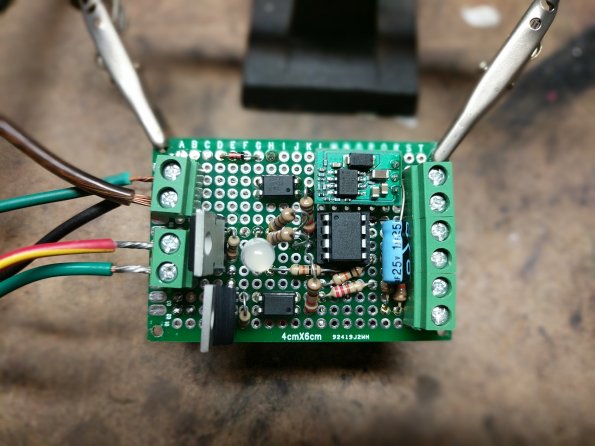
It's powered by a simple ATTin85 arduino chip, with a couple of P-Channel MOSFETs to drive the hight-current loads of the signal lights. The "magic" is an Infrared sensor that can detect the turning of the steering wheel without the need for any mechanical connection. Just a bit of black paint on the steering shaft is all it took.
Anyway.. I had been bench testing my prototype board for weeks.. this weekend I finally got to "install" it and see if it actually does what I expect it to do.. and it does!!
The software for this module will be made full opensource, the circuit board design (it's pretty trivial anyway) will also be made full open source, as well as the PCB layout once I've done re-designing it. I'll also put together a full DIY writeup on my main build site for all to use. I tried to make it such that retro-fitting one of these into an already built car would not be too hard, and require minimal changes to an existing setup. They are still on their way to my house, but I ordered a small PVC mounting box to house the module. It won't be left perched on the frame like that.
Specs:
- Switched 12v and ground power the module. It's can handle 6v to 24v of input. Should be more than fine on a noisy 12v car electrical system.
- The MOSFETs drive each of the left and right 12v+ outputs to the signal lights (should work with LEDs as well as regular incandescent bulbs).
- The signal inputs are driven from a momentary SPDT (on)-off-(on) toggle switch, with all 3 pins wired to inputs on the module.
- The IR sensor has 3 control wires, all plugged directly into the module.
- Includes ability to act as Hazard flasher also ( I simply didn't use this feature and instead kept the hardware Flasher module and Diodes installed )
Here's a pic of the prototype board after I was done soldering it all together
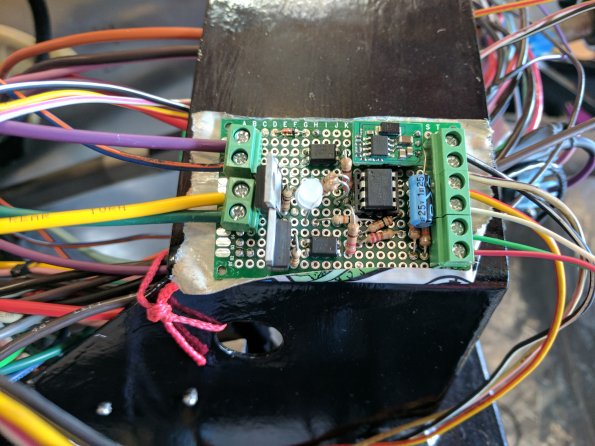
Temporary Mounted to frame with some tape for Testing.
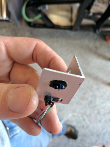
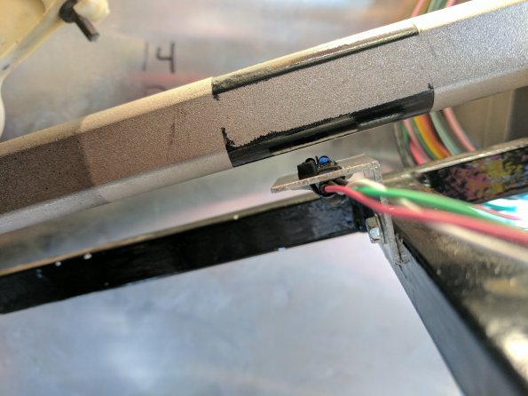
The IR Sensor mounted in a piece of angle aluminum
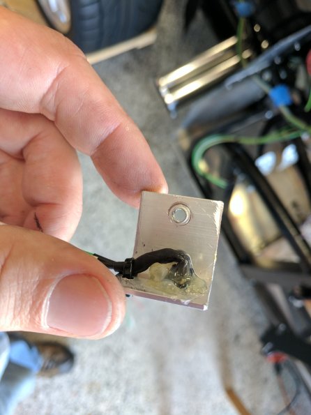
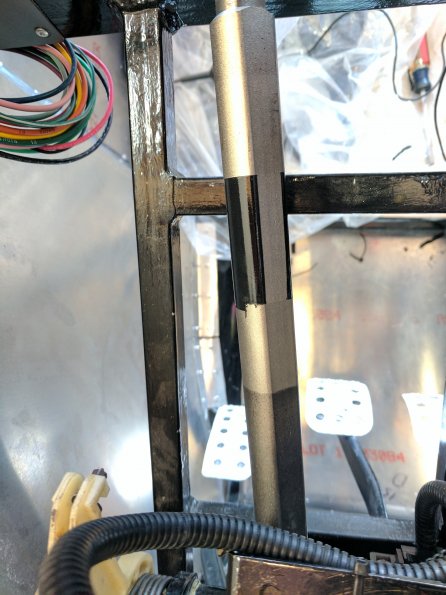
The steering shaft with the black paint applied for the IR Sensor to detect.
The IR sensor mounted below the steering shaft.
Anyway.. Like I said.. It worked.. couldn't wait to share... so .. voila!! Once I get this car actually driving.. and shake out any bugs.. I'll keep this thread informed.
Last edited by skidd; 10-27-2022 at 10:48 AM.
-
Post Thanks / Like - 1 Thanks, 4 Likes


 Thanks:
  Likes:


 Reply With Quote
