-
Senior Member


Originally Posted by
Fman

John, very nice work on your dash, that looks awesome! What did you do for dash material, did you pick up a hyde or use supplied FFR material?
Thanks, Fman! 1/2 a cowhide, from the Leather Hide Store. Nice site and good service. And beautiful leather.
MK4 #7838: IRS 3.55 TrueTrac T5z Dart 347
The drawing is from ~7th grade, mid-1970s
Meandering, leisurely build thread is
here
-
Senior Member

Originally Posted by
John Ibele
Thanks, Fman! 1/2 a cowhide, from the Leather Hide Store. Nice site and good service. And beautiful leather.
Looks like quality leather John, I noticed your speedo... did you get the indicator lights in your speedo? (turn and high beams). Maybe it is in the picture and my eyes cant see it. When I installed mine I was surprised to find this, had no idea Speedhut added this to there Vintage package. If you do not have it and want it you could send it in and have them add it on. I just sent my water temperature gauge in to be converted to Fahrenheit, they only charge $14 to do this plus shipping. Speed hut has been great to work with.
-
Senior Member
Originally Posted by
Fman
Looks like quality leather John, I noticed your speedo... did you get the indicator lights in your speedo? (turn and high beams). Maybe it is in the picture and my eyes cant see it. When I installed mine I was surprised to find this, had no idea Speedhut added this to there Vintage package. If you do not have it and want it you could send it in and have them add it on. I just sent my water temperature gauge in to be converted to Fahrenheit, they only charge $14 to do this plus shipping. Speed hut has been great to work with.
You saw correctly, its the pre-GPS speedo which came with my pre-2015 vintage kit. Thanks for the prompt, though, I may ask Speed Hut what the cost would be to swap it out. I should at least know what I'm missing and what it would cost to get it. With the competition layout obviously the indicator lights in the speedo aren't ideally located, so I'd still be in favor of using the dedicated blinker lights.
Speed Hut - I've had the same experience. Sent in the temp gauge for the conversion to Fahrenheit, no questions asked, nominal fee, and quick turnaround. Nice to see that.
MK4 #7838: IRS 3.55 TrueTrac T5z Dart 347
The drawing is from ~7th grade, mid-1970s
Meandering, leisurely build thread is
here
-
Post Thanks / Like - 0 Thanks, 1 Likes
 Fman
Fman liked this post
-
Senior Member

With the competition layout obviously the indicator lights in the speedo aren't ideally located, so I'd still be in favor of using the dedicated blinker lights.
From experience, the integral turn indicator & Hi-Beam indicator on the speedo are totally useless in the SC layout. They're not the hyper-bright LEDs, and being "way over there" you can hardly see them in daylight. My dash layout is similar to yours, and I have a single jeweled indicator lamp (LED driven) between the tach & OP. It's got steering/blocker diodes in-line so a single indicator will work with dual inputs.
I'm still relying upon the Hi-Beam indicator in the speedo, but when it's in use it's dark out, and it works fine. (plus you should kinda know if your brights are on anyway...)
John D. - Minneapolis 'Burbs
1965 El Camino - LT-1, 4L60e, 4wh discs, SC&C susp.
2013 F-150 Platinum - Twin Turbo 3.5
2018 Mk4 Roadster w/ Coyote - #9365 - Build Thread Delivery 7/3/18, 1st Start 1/4/19, 1st Road Mile 5/5/19, Legal 6/18/19, In Paint 2/25/21, Done (?) 4/2021
-
Senior Member

Speedhut converted my non-GPS speedo to a GPS one. I asked them not to change the face plate or add the directionals. IIRC it was about $100 and a week or so turnaround.
FFR #8833 289 FIA 3-link
1965 289, TKO600 from Forte's Parts Connection
Body and Paint by Mike's Auto Restoration
Picked up 3/5/2016, First start 4/22/2017, MA legal 7/11/2018
Build Thread
http://thefactoryfiveforum.com/showt...FIA-build-8833
"Insanity is contagious" - Joseph Heller
-
Senior Member
Originally Posted by
cnutting
Speedhut converted my non-GPS speedo to a GPS one. I asked them not to change the face plate or add the directionals. IIRC it was about $100 and a week or so turnaround.
Ah, thanks, that sure sounds reasonable. I'm sure I can put it together by looking through their material, but ... since you probably have it in your head, major advantages for the GPS vs pre-GPS speedo? Are you happy with the choice?
MK4 #7838: IRS 3.55 TrueTrac T5z Dart 347
The drawing is from ~7th grade, mid-1970s
Meandering, leisurely build thread is
here
-
Senior Member
I had some wiring glitches and this was an easier installation. I got lazy near the end. 
Yes, I am happy with it. Simple process, good service.
FFR #8833 289 FIA 3-link
1965 289, TKO600 from Forte's Parts Connection
Body and Paint by Mike's Auto Restoration
Picked up 3/5/2016, First start 4/22/2017, MA legal 7/11/2018
Build Thread
http://thefactoryfiveforum.com/showt...FIA-build-8833
"Insanity is contagious" - Joseph Heller
-
Post Thanks / Like - 1 Thanks, 0 Likes
-
Senior Member
Originally Posted by
John Ibele
You saw correctly, its the pre-GPS speedo which came with my pre-2015 vintage kit. Thanks for the prompt, though, I may ask Speed Hut what the cost would be to swap it out. I should at least know what I'm missing and what it would cost to get it. With the competition layout obviously the indicator lights in the speedo aren't ideally located, so I'd still be in favor of using the dedicated blinker lights.
Speed Hut - I've had the same experience. Sent in the temp gauge for the conversion to Fahrenheit, no questions asked, nominal fee, and quick turnaround. Nice to see that.
I also have two dedicated indicator lights for turn signals, how are you wiring those into the harness?
-
Senior Member
Originally Posted by
Fman
I also have two dedicated indicator lights for turn signals, how are you wiring those into the harness?
Hey Fman. I ... dunno. Not quite there yet. Spent my first quality time with the gauge instructions last night, and I'll probably work on getting those sorted before hooking things up to the harness.
Then I had a thought that maybe I'm not ready yet to trade in my newly-honed skills in leather and aluminum fab for my nearly complete ignorance in the wiring department, which would mean building a console storage compartment before turning to wiring ") . Jeez you can drive yourself nuts building these things.
. Jeez you can drive yourself nuts building these things.
If I go that route I'd be a few weeks away from sorting the wiring out. We'll see which way my brain goes when I head to the garage on Saturday morning!
MK4 #7838: IRS 3.55 TrueTrac T5z Dart 347
The drawing is from ~7th grade, mid-1970s
Meandering, leisurely build thread is
here
-
Post Thanks / Like - 0 Thanks, 1 Likes
Fman liked this post
-
Senior Member

Originally Posted by
John Ibele
Forgot to include a shot showing how the hinges worked out. They should work fine - I calculated clearance without foam and leather, so they get slightly compressed at the bottom of the glovebox door when you open it. But, its only a slight compression and leaves no marks. The required cutout inside the box is no bigger than for the hinges others have used, and these are compact, sturdy and have a nice look. I would use them again (and will probably do so on a console box under the dash).
Beautiful work and thank you for putting so much detail into your build thread. I am learning from all of you guys!
Matt
FFR Complete Kit, Coyote, Tremec TKX, 3.73 IRS, power steering, 18" Halibrands, Wilwood brakes, Gas-N pipes + header, Viking blue color
Roadster Build Time Tracker
-
Post Thanks / Like - 1 Thanks, 0 Likes
-
Senior Member
Hey thanks, richtersand! You too - having fun keeping tabs on your build (even if I'm not keeping up!)
MK4 #7838: IRS 3.55 TrueTrac T5z Dart 347
The drawing is from ~7th grade, mid-1970s
Meandering, leisurely build thread is
here
-
Senior Member
Well, I said I was moving on to wiring, but clearly I wasn't ready to leave my newly developed competence in working with aluminum, foam and leather quite yet. I had an idea for putting in a console storage box to augment the tiny storage area in the heater-constrained glove compartment. You know how these things go ... some personal touches on these cars are rationally planned out with deliberately weighted pros, cons and tradeoffs, and some of are of "I'm just gonna do it" variety. This was a combination of both, I guess. I liked the challenge of trying to hit a target that combines a consistent look with the right balance of functionality, and the right nod to the car's heritage.
So, with that rambling out of the way, my seat-of-the-pants design specs:
- Finish & Aesthetics
- Continue the 'broad arch' theme with the same kitchen cabinet pull used on the glove box, and a top to the door that mirrors the curve of the top of the dash.
- Tie in the angles of the transmission tunnel by having the sides line up flush with the tunnel sides.
- Soften the look with 1" radius corners from front face to sides
- Inset an inch or so from the dash face, which seems more in line with the 'vintage tribute' vibe to me.
- Leather and stainless
- Function
- Additional storage
- USB charger access
- Hidden main cutoff switch
Once I had the general idea in my head I started with poster paper, duplicating the angles of the transmission sides and sketching in the door outline. (It's tough to get the angles to look right, with the transmission tunnel lacking symmetry to the center line of the car no matter your perspective. It showed on the paper when laying it out, but fortunately gets hidden by the rounded corners of the console when finished.)
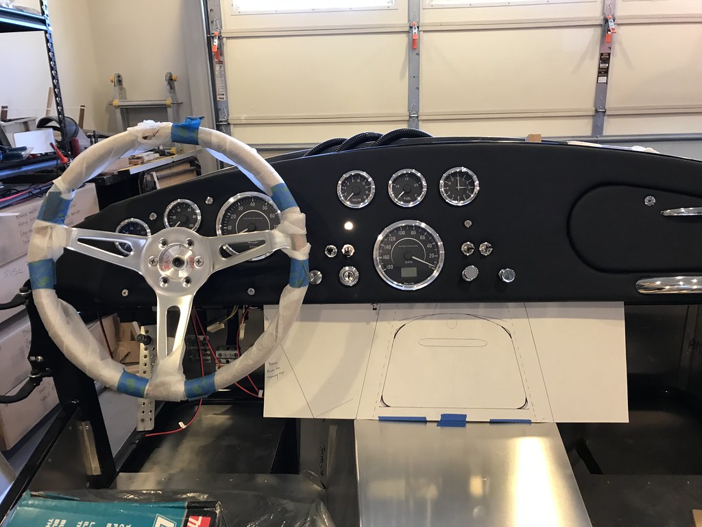 Untitled by John Ibele, on Flickr
After some playing around with various options I ended up with a layout for the front face and door that I liked.
 Untitled by John Ibele, on Flickr
After getting to this point I left the poster paper behind and started taking angles directly off the car with the t-bevel and going straight to aluminum. The challenge in this project for me was going to be getting the rounded corners to look right with all the different angles going on, and getting the cubby sides to come in co-planer with the tunnel sides. I started with flat inner stiffener panels, riveted to the console bottom at the right angles to match the tunnel sides and for the front, the angle of the dash:
 Untitled by John Ibele, on Flickr
I did bends on all 4 sides of the inner panels. Since I don't have a box break the final two bends were done with a hand seamer, which works fine for small stuff like this.
Next up was the rounded corners. You can use your cheapie brake to do this, by bending the aluminum around a pipe of the right diameter. Clamp the pipe down on top of the aluminum sheet, holding it tight to the horizontal plate of the brake. Then you can bend the sheet around the pipe. I took the clamps off in this shot ... the pipe is where it was clamped. The backer board is clamped down to keep the pipe from sliding away from the corner as you begin bending the aluminum.
 Untitled by John Ibele, on Flickr
I started with a 2" diameter pipe, but you have to factor in some relaxation of the metal. Another trip to Ace for an 18" section of 1-1/4" plumbers pipe did the trick ... a little playing around got just the right angles with just the right overall width to fit the inner box I had made:
 Untitled by John Ibele, on Flickr
Next up was gluing the two pieces together. I used duct tape to pull the 3 panels inward before spraying with S77. That way I could line up the outer piece with the front panel and adhere that before pressing the side panels in place.
After a little cleanup with the jigsaw and the mill file, it looks pretty good:
 Untitled by John Ibele, on Flickr
Last edited by John Ibele; 03-13-2021 at 10:46 PM.
MK4 #7838: IRS 3.55 TrueTrac T5z Dart 347
The drawing is from ~7th grade, mid-1970s
Meandering, leisurely build thread is
here
-
Senior Member
Next was laying out and cutting the door opening ...
 Untitled by John Ibele, on Flickr
... and getting the door mounted:
 Untitled by John Ibele, on Flickr
Setup for spraying the foam and leather was pretty much the same drill as for the dash ... front face for step one, with masking over what will become the pie cuts, then a lot of masking of the cubby itself to spray the pie cuts in step two:
 Untitled by John Ibele, on Flickr
  Untitled by John Ibele, on Flickr
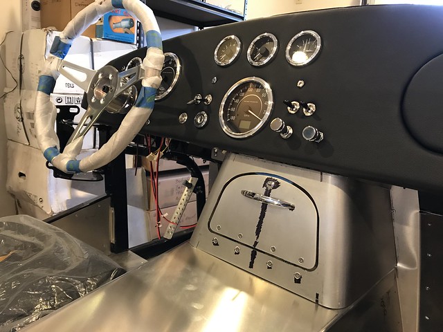
Here's the end result:
 Untitled by John Ibele, on Flickr
 Untitled by John Ibele, on Flickr
I'm really happy with how it turned out. It's not a lot of storage but its enough. The sides tied in very well with the tranny tunnel, and the rounded corners soften the look of the whole thing.
I used the Soss hinges again, with the same result - very sturdy, nice action, and a nice look.
 Untitled by John Ibele, on Flickr
They're slightly stiff for just that first opening as it pushes against the foam / leather around the hinge. But it doesn't seem to permanently compress the foam, and I'd use them again. For a leather / foam combination that's thicker than what I have, you need to go with a different option.
Okay, maybe I'm ready to leave leather and aluminum fab behind for real this time, and turn to getting this thing wired up. It got up to 60F in Minneapolis today, and my dyno-tested engine is staring at me accusingly from the corner of the garage.
MK4 #7838: IRS 3.55 TrueTrac T5z Dart 347
The drawing is from ~7th grade, mid-1970s
Meandering, leisurely build thread is
here
-
Post Thanks / Like - 0 Thanks, 5 Likes
-
Senior Member

This is fantastic. I was/am planning something very similar. I do not have a glovebox and opted to omit it due to the heater. The only reasonable space left up front is under the dash. Thank you for documenting this the way you did it really provides a great blue print for how to get started. Terrific craftsmanship
MK4 #10008 - Ordered 10/06/20, Delivered 03/03/21, First Start 7/22/21, First Go Kart 7/24/21
Paint by Metal Morphous 5/14/22, Legally registered 6/8/22, Graduated 7/20/22
Build Thread
https://thefactoryfiveforum.com/show...been-delivered
Complete Kit, Ford 306, Sniper/Dual Sync, T5, Hydraulic clutch
-
Post Thanks / Like - 1 Thanks, 0 Likes
-
Senior Member
John, well done! Your dash looks perfect and the storage cubby is a great addition to it. You got some great fab skills!
Are you leaving the trans cover under it?
Last edited by Fman; 03-14-2021 at 01:33 PM.
-
Post Thanks / Like - 1 Thanks, 0 Likes
-
Senior Member
Hey thanks guys! Yep, leaving the trans tunnel as is. I’ll drill up from the bottom into the cubby, then put nut-serts in the tunnel top to screw the cubby down onto. I’ll put leather on the top of the tunnel. I’m thinking of putting some polished stainless steel strips on the sides of the tunnel top, and screwing through those to hold the top in place. Would provide a good highlight between the leather above and carpet below.
MK4 #7838: IRS 3.55 TrueTrac T5z Dart 347
The drawing is from ~7th grade, mid-1970s
Meandering, leisurely build thread is
here
-
Senior Member

Very nice, John! Wow! You could have fooled me you're new at this sort of thing. 
Chris
Coupe complete kit delivered: 4/22/24.
Build Thread. Coyote. T-56. IRS w/3.55. Wilwoods. PS. HVAC. Side windows.
MK4 Complete kit.
Build Thread Index. Delivered: 10/15/2020. Legal: 7/25/23. Coyote Gen3. TKO600 (0.64 OD). IRS w/3.55. PS. Wilwoods. Sway bars. This build is dedicated to my son, Benjamin.
Build Thread.
-
Post Thanks / Like - 1 Thanks, 0 Likes
-
Senior Member
Originally Posted by
460.465USMC
Very nice, John! Wow! You could have fooled me you're new at this sort of thing.
Hey thanks, Chris! I'm feeling more lucky than good ... as we've all learned when you're doing things for the first time, you can plan all you want but you can't be assured of success. I have a lot of woodworking experience in my past, and I think it just took a while for the experience there to transfer over to metal.
I'm hoping the glow over how the dash turned out will carry me through the complete ignorance phase of wiring! Started in on that last night, just figuring out how to keep things sorted behind the dash.
MK4 #7838: IRS 3.55 TrueTrac T5z Dart 347
The drawing is from ~7th grade, mid-1970s
Meandering, leisurely build thread is
here
-
This is beautiful work! You're making my gears turn.
-
Post Thanks / Like - 1 Thanks, 0 Likes
-
03-17-2021, 01:41 PM
#100
Wow John your craftsmanship is top notch.
I've gone the lazy way on the dash and ordered a Acton Cobra one with the glove box cutout and door panel. I was thinking of TIGing on the attachment brackets, but your trick of backing up the counter sinked holes seems the way to go. I have been thinking what to use as a keyed lock for the glove box and it seems you have it. Any chance of sharring where you got your lock?
Get ideas you have and thanks for sharing John
-
Post Thanks / Like - 1 Thanks, 0 Likes
-
03-17-2021, 03:45 PM
#101
Senior Member
Originally Posted by
v1-vr
Wow John your craftsmanship is top notch.
I've gone the lazy way on the dash and ordered a Acton Cobra one with the glove box cutout and door panel. I was thinking of TIGing on the attachment brackets, but your trick of backing up the counter sinked holes seems the way to go. I have been thinking what to use as a keyed lock for the glove box and it seems you have it. Any chance of sharring where you got your lock?
Get ideas you have and thanks for sharing John
Hey thanks, and no problem sharing! This was a Grainger product, 1XRY4. Yep, they're smallish, but the keys don't look like toys, typical cabinet key size. HTH, -- John
MK4 #7838: IRS 3.55 TrueTrac T5z Dart 347
The drawing is from ~7th grade, mid-1970s
Meandering, leisurely build thread is
here
-
03-17-2021, 05:26 PM
#102
-
03-18-2021, 07:29 PM
#103
And I thought I was done with my center console. I made an open area with a door to cover my re-located fuse panel. Now that I see your handy work I like the outer door with a lock on it. I might have to borrow this to make an improvement. Thanks for the details!
-
Post Thanks / Like - 1 Thanks, 0 Likes
-
03-21-2021, 09:27 PM
#104
Senior Member
Well, maybe I'm starting to move through the 'sit and stare at it' phase and the 'kicking my butt' phase, and into the phase where I'm actually starting to make progress on wiring. But I have newbie questions which I think I'll throw out there to make sure I'm headed in the right direction. I think part of my problem is my older-vintage wiring harness doesn't match what most others are doing, and my older rev instructions just leave a lot of detail out. I have the new revision for the wiring manual, but of course the wiring harness isn't quite the same.
Or ... I'm just slow
I have the fuse panel mounted and the main harness lying in place, and the front and rear harnesses are in place on the frame as well. I started working on wiring the back of the dash, and got the gauges hooked up and things neatened up a bit:
 Untitled by John Ibele, on Flickr
I have the power and light daisy chains hooked up per Kleiner's thread and I'm fine with all that. There are a few things that threw me off though. For one, each gauge (except clock) should hook up to a sender through the white plugs I've got in my hand in the photo. There aren't any matching plugs like that on the harness. You can see some in the bags above the dash in the photo, though, connected to wires in those bags. There's another example in the photo below, with a weather pack connecter on the other end. My assumption is that these wires were to be used if you weren't working with a wiring harness, and were a standard part of the gauge set at the time. The gauge instructions suggest this but aren't very clear about it.In the bottom photo there's a picture of the dash harness. Most of the gauge connections terminate in female spade connectors. Connections to controls on the dash terminate in the black connectors, for which there don't appear to be any matching terminals to use on the dash side.
Based on those observations and assumptions, here's my plan:
- Clip off any weather pack connectors like the one shown below leaving a few inches of wire, and connect them to the appropriate wires in the sender harness.
- Clip off the white plugs as well, and connect them to the appropriate wires in the dash harness, so I have plugs to match those in the photo above and can have a plug connection into the dash harness from each gauge.
- For the dash harness wires with spade connections, leave them in place, and terminate the wires coming off the dash in corresponding male spade connectors.
- Clip off the black connectors on the dash harness, and replace with spade connectors. I'm concerned about the fact that some of these are heavier gauge wire, and there are multiple wires going into these connectors. Am I missing something here?
My only other general question is whether I should be soldering any connections directly to the matching item on the dash, rather than always going through a connector. I can see the convenience of having a plug connection for every item, but also know there's 3 solder or crimp connections instead of 1, and therefore a reliability tradeoff. With no background in this kind of wiring, just wanting to know the best practice or convention here, so I can follow it.
Let me know where I went off track, otherwise I'm forging ahead.
 Untitled by John Ibele, on Flickr
 Untitled by John Ibele, on Flickr
Last edited by John Ibele; 03-21-2021 at 09:49 PM.
MK4 #7838: IRS 3.55 TrueTrac T5z Dart 347
The drawing is from ~7th grade, mid-1970s
Meandering, leisurely build thread is
here
-
03-21-2021, 10:06 PM
#105
Senior Member

You have an older revision of the Ron Francis harness and isn't plug and play with your Speedhut gauges. So yes, lop off those white connectors and directly attach to the RF wires. I personally would also remove the spade connectors. Leaving them in place is OK. But then you add a mating connector with yet another crimp connection plus the spade connection. I'd personally rather have it hard wired. But that's strictly a personal preference.
Your picture of the Speedhut sending unit cable is another choice you have to make. Some will use it as is, e.g. home run from the sending unit on the engine side to the gauge connection. Bypassing the provided sending unit wire in the RF harness. Others (like me) use the RF wire out of the gauge harness so that those three large RF connectors basically disconnect the entire dash. Then splice the RF sending unit cable somewhere in the harness behind the dash or in the engine compartment. Pros and cons for each approach.
You'll get lots of opinions about soldering. My recommendation is if it's not something you've had the tools or are experienced with, don't. Done properly, e.g. very light touch with the least amount of heat and solder possible, it's OK. But otherwise very easy to do more damage than good. People will point out that DD's typically don't have soldered connections. True. But all the terminals and connectors are assembled with dedicated high-end machines where there's a lot of science with the crimps, pull tests, etc. Spent my career around that stuff. With the right tools, e.g. a decent to high end crimper, the right dies, and some practice, DIY can be done well.
Good luck.
Last edited by edwardb; 03-21-2021 at 10:14 PM.
Build 1: Mk3 Roadster #5125. Sold 11/08/2014.
Build 2: Mk4 Roadster #7750. Sold 04/10/2017.
Build Thread
Build 3: Mk4 Roadster 20th Anniversary #8674. Sold 09/07/2020.
Build Thread and
Video.
Build 4: Gen 3 Type 65 Coupe #59. Gen 3 Coyote. Legal 03/04/2020.
Build Thread and
Video
Build 5: 35 Hot Rod Truck #138. LS3 and 4L65E auto. Rcvd 01/05/2021. Legal 04/20/2023.
Build Thread. Sold 11/9/2023.
-
03-21-2021, 10:09 PM
#106
Before cutting anything you should look at all of your gauge sending units. I would assume that the sending units are a 2-wire version and the weather pack ends plug into them. If you have the older harness which is set up for 1-wire sending units you might need to abandon the wires in the harness and run the wires that came with your gauges. Enjoy your wiring adventure!
-
03-22-2021, 08:57 AM
#107
Senior Member
Originally Posted by
edwardb
You have an older revision of the Ron Francis harness and isn't plug and play with your Speedhut gauges. So yes, lop off those white connectors and directly attach to the RF wires. I personally would also remove the spade connectors. Leaving them in place is OK. But then you add a mating connector with yet another crimp connection plus the spade connection. I'd personally rather have it hard wired. But that's strictly a personal preference.
Your picture of the Speedhut sending unit cable is another choice you have to make. Some will use it as is, e.g. home run from the sending unit on the engine side to the gauge connection. Bypassing the provided sending unit wire in the RF harness. Others (like me) use the RF wire out of the gauge harness so that those three large RF connectors basically disconnect the entire dash. Then splice the RF sending unit cable somewhere in the harness behind the dash or in the engine compartment. Pros and cons for each approach.
You'll get lots of opinions about soldering. My recommendation is if it's not something you've had the tools or are experienced with, don't. Done properly, e.g. very light touch with the least amount of heat and solder possible, it's OK. But otherwise very easy to do more damage than good. People will point out that DD's typically don't have soldered connections. True. But all the terminals and connectors are assembled with dedicated high-end machines where there's a lot of science with the crimps, pull tests, etc. Spent my career around that stuff. With the right tools, e.g. a decent to high end crimper, the right dies, and some practice, DIY can be done well.
Good luck.
Thanks for chiming in, Paul. Confirms my general direction, and bolsters my confidence in lopping off the connectors on the harness and hard wiring in. And yep, didn't mean to re-open the soldering topic itself. As you suggest, I think that question is best answered based on individual experience and tools available. For me, plenty of past experience soldering from the RC modeling world and kids' projects, so I'm most comfortable with that approach. And in thinking about it, any 'quick connect' option behind the dash isn't really that anyway, not once you've diagnosed the problem, removed the dash, replaced the switch ... I'll side with the minimum number of connections, made in a way that's most reliable based on my ability and tools.
Originally Posted by
D Stand
Before cutting anything you should look at all of your gauge sending units. I would assume that the sending units are a 2-wire version and the weather pack ends plug into them. If you have the older harness which is set up for 1-wire sending units you might need to abandon the wires in the harness and run the wires that came with your gauges. Enjoy your wiring adventure!
Good catch. I know I want to have the harness do the work between sensor and dash, but I'll make sure I have ground figured out before picking up the wire cutters.
Thanks, guys!
MK4 #7838: IRS 3.55 TrueTrac T5z Dart 347
The drawing is from ~7th grade, mid-1970s
Meandering, leisurely build thread is
here
-
06-07-2021, 10:38 AM
#108
Senior Member
Dash Wiring, Trunk Aluminum, Crowded in the Garage ...
I haven't left an update in a few months but have been making steady progress so I figured it's time for an update. I pushed through my dash wiring overthinking after Paul's response and a pep talk from Fixit. After thinking through the process beforehand there's nothing like just getting started, and learning from experience what works best for you in terms of all the wiring connections. I ended up with solder for wire-wire connections where needed. With some practice, I got joints that were properly flowed without dumping excess heat into the joint, properly strain relieved with heat shrink tubing. I used crimp connections at terminations, where I built confidence by just doing an informal pull test after crimping.
I didn't tread much new ground so not a lot of photos of the back of the dash. I used mini-LED indicator lights for turn signals, high beam and warning light, and they are indeed bright enough to sear your eyeballs at night. I found a cheap LED dimmer, and breadboarded it to confirm that it could be used on the ground side of the circuit, and that it would remember the last dimming setting when the power was turned off (it did). So, I needed only one dimmer for all the dash indicator lights.
After confirming this, I set up a relay hooked up to the headlights so that when they are on, the dash indicator lights have a ground path through the dimmer, and when the lights are off, the dash indicators are wired straight to ground (undimmed). It works great; they dim nicely when the lights are turned on. There's one minor refinement to add. When the dimmer is in the circuit and one light is on, you can see a very faint glow in the lights which are not on. This should be easily taken care of with a diode in the circuit.
To verify everything worked right I mounted the dash and hooked up a lantern battery to power the gauges, and then did the obligatory session sitting in the car with the garage lights out, and the gauge lights glowing. That leaves only the heater and wiper wiring to go. I would have continued with that, but the garage got crowded:

Untitled by John Ibele, on Flickr
That's a one-family truck, originally owned by my grandfather who was the Studebaker dealer 'up North', and kept in the family ever since. I brought it down from the cabin to take to Back to the 50's, coming up in a few weeks. BTT50's is quite an experience ... 5:45 in the morning, you line up to get in to one of three entrances to the MN state fairgrounds, and you have over a mile of cars ahead of you in line, each one pre-1964, and something you'd want to look at and chat with the owner about. Over 10,000 pre-1964 vehicles all in one place.
Hope you'll indulge the off-topic item ... just figured that's reasonably cool for car folks. And while fun, it does impact the space for car building. I can always roll the body buck off the car and continue working as I was, but when I'm still mostly working on the car an hour here and an hour there, much better to just get the trunk finished up since its accessible.
I hit the 60 year mark and got a nice air compressor from the family in recognition ... now there's a family that cares! First tool purchase was a rivet gun. While I've pulled all the rivets with a hand tool so far, boy was I happy to have this guy before doing the trunk. Very nice. Our eldest stopped over to help out for a bit:

Untitled by John Ibele, on Flickr
I was pleased with how things turned out, with only some minor additions still to go. I have to add the patch below the anchor for the PS tank strap (sitting on the lip of the trunk in this photo), and another one just above it for the tab I removed from the frame.

Untitled by John Ibele, on Flickr
I needed to add the patch panels on the outside after getting the upper trunk aluminum in place. It worked out fine, but provided a good reminder to thoroughly mock up everything beforehand to ensure the right order of assembly. No harm done in this case:

Untitled by John Ibele, on Flickr
The last step is to fab some panels for the inner sides of the upper trunk region. Ideally I would have done these with a lip at the bottom, tucked under the upper trunk bottom. Did I mention the value of thoroughly mocking up everything beforehand ... no big deal, it will be fine without that addition, since its really just going to be there to clean things up and make it all easier to carpet.

Untitled by John Ibele, on Flickr
It's nice to be at the point where fabbing additional aluminum pieces is reasonably efficient, which only comes after a certain amount of practice. Once I have the side pieces done I'll just continue with carpeting the trunk and finishing it up, since it's what's easily accessible until the end of June.
Last edited by John Ibele; 06-07-2021 at 10:43 AM.
MK4 #7838: IRS 3.55 TrueTrac T5z Dart 347
The drawing is from ~7th grade, mid-1970s
Meandering, leisurely build thread is
here
-
Post Thanks / Like - 0 Thanks, 1 Likes
Fman liked this post
-
06-07-2021, 04:08 PM
#109
Senior Member
You inspired me to do the same with the trunk panels. Great call and I'm glad you got to spend some time on the build with your son.
MK4 #10008 - Ordered 10/06/20, Delivered 03/03/21, First Start 7/22/21, First Go Kart 7/24/21
Paint by Metal Morphous 5/14/22, Legally registered 6/8/22, Graduated 7/20/22
Build Thread
https://thefactoryfiveforum.com/show...been-delivered
Complete Kit, Ford 306, Sniper/Dual Sync, T5, Hydraulic clutch
-
06-07-2021, 04:39 PM
#110
Senior Member
Originally Posted by
Blitzboy54
You inspired me to do the same with the trunk panels. Great call and I'm glad you got to spend some time on the build with your son.
Ha, Jesse I think the inspiration goes both ways. I saw your last build post, and realized I was stopping at HD on the way home to grab some aluminum tape, then it went from there.
Looked at your last post ... looked like you had already fabbed side panels? Anyway the only piece I still need to solve is how to get the darn thing where I want it. Looks like I may need to do a small patch panel up where seat belt anchor comes up from the frame. Just not enough space to get things tilted into place ... see if I can puzzle through that next.
MK4 #7838: IRS 3.55 TrueTrac T5z Dart 347
The drawing is from ~7th grade, mid-1970s
Meandering, leisurely build thread is
here
-
06-07-2021, 04:59 PM
#111
Senior Member
looked like you had already fabbed side panels?
Yeah but I literally just fab’d them up this afternoon
It went pretty fast actually
MK4 #10008 - Ordered 10/06/20, Delivered 03/03/21, First Start 7/22/21, First Go Kart 7/24/21
Paint by Metal Morphous 5/14/22, Legally registered 6/8/22, Graduated 7/20/22
Build Thread
https://thefactoryfiveforum.com/show...been-delivered
Complete Kit, Ford 306, Sniper/Dual Sync, T5, Hydraulic clutch
-
06-07-2021, 07:32 PM
#112
Looking good John. I think we're going to need some more pictures of the truck. It looks beautiful and it's so awesome that you have kept it in the family.
MK4 Complete Kit, EFI 427W/TKO 600, 2015 IRS
Ordered: 11/6/20, Kit Completion: 2/13/21, Picked Up: 2/16/21, Build Started: 2/19/21, First Start: 6/13/21, Go Kart: 8/15/21, Sent for Paint: 12/23/21, Back From Paint: 6/16/22, Street Legal: 7/11/22
-
Post Thanks / Like - 1 Thanks, 0 Likes
-
06-08-2021, 10:34 AM
#113
Senior Member
Originally Posted by
NYMike
Looking good John. I think we're going to need some more pictures of the truck. It looks beautiful and it's so awesome that you have kept it in the family.
Thanks, Mike. I'll probably post a few photos in another forum on here, including a shot of the drive in at the beginning of the event ... pretty impressive sight. Bummer about your radiator - good recovery though!
MK4 #7838: IRS 3.55 TrueTrac T5z Dart 347
The drawing is from ~7th grade, mid-1970s
Meandering, leisurely build thread is
here
-
06-09-2021, 10:35 PM
#114
Senior Member
Glad to read about your progress. It's been a while, so I was thinking about sending you a PM to see how things are going.
That Studebaker looks really nice, and the best part is, of course, its family history. That's great. Looking forward to those promised pictures of BTT50s!
Happy birthday! An air compressor is such a great gift. No doubt it will be a workhorse in your garage. I'm also hitting a milestone this summer, but one decade behind you.
Thanks for the great updates.
Chris
Coupe complete kit delivered: 4/22/24.
Build Thread. Coyote. T-56. IRS w/3.55. Wilwoods. PS. HVAC. Side windows.
MK4 Complete kit.
Build Thread Index. Delivered: 10/15/2020. Legal: 7/25/23. Coyote Gen3. TKO600 (0.64 OD). IRS w/3.55. PS. Wilwoods. Sway bars. This build is dedicated to my son, Benjamin.
Build Thread.
-
Post Thanks / Like - 0 Thanks, 1 Likes
-
08-09-2021, 05:05 PM
#115
Senior Member
Got a big summer milestone behind us with our daughter's wedding in the end of July, so phase two of the summer should have more build time in store. It's great to get back at it.
I finished off the two interior panels to give the trunk a more finished look prior to doing the trunk liner.

Untitled by John Ibele, on Flickr
I did a one-piece panel on the driver's side, but it needs a clearance slot to get around the seat belt anchor. I liked the two-piece / no cutout version better.
The Thermo-Tec in the trunk is maybe a bit of overkill, but once you hear the 'ping' turn into a nice solid 'thunk' it's hard to stop. I figured it can't hurt (other than a bit of weight and $$) ... and possibly can help a lot in a more solid feel and a much more limited rattle patrol once the car is on the road. Anyway, it's easy to work with and really makes things sound and feel solid once in place.

Untitled by John Ibele, on Flickr
I tackled the trunk liner next ... went back and forth about how to handle the finish on the gas tank access covers and eventually decided to leave them natural aluminum. The trunk liner was pretty easy to work with, although plan on going through utility blades at a pretty quick rate. I used the Weldwood outdoor carpet adhesive as others have, and after realizing that the adhesive has good initial tack without any wait time whatsoever, it worked well for me.

Untitled by John Ibele, on Flickr
I didn't carry the liner up over the top of the frame on the sides, figuring this area was going to be virtually invisible. And ... well, there's the hole through the frame as well. Am I good to go, or do I need to cap those?

Untitled by John Ibele, on Flickr
Last step was to measure the back of the cockpit rear panel for trunk liner and apply before installing the rear panel. That worked great, and I'm sure far easier than installing after the fact.
Before installing the rear panel, I just had to reposition the rear panels where the tranny tunnel meets the rear panel. In sighting down the frame where the rear cockpit panel was going to be riveted in place, I noticed the mating surface on these panels was tilted simply too far to the rear. They needed to be rotated so that the mating surface was co-planar with the frame, giving a planar mounting surface to the rear cockpit panel. Easier to view than to explain; hope that makes sense.
Anyway, not my proudest workmanship moment, but certainly none the worse for wear and completely invisible once the Thermo-Tec and carpet is in place. I feel better now.

by John Ibele, on Flickr
I riveted the back panel in place. Wow, nice to see that view of the aluminum without all the Clecos in there. The aluminum tape should be redundant with the silicone in the joint, but it seemed like good insurance and doesn't take long. I'll finish that up before moving on.

Untitled by John Ibele, on Flickr
Feels good to be back in the garage again and making some forward progress!
Last edited by John Ibele; 08-10-2021 at 09:14 AM.
MK4 #7838: IRS 3.55 TrueTrac T5z Dart 347
The drawing is from ~7th grade, mid-1970s
Meandering, leisurely build thread is
here
-
Post Thanks / Like - 1 Thanks, 3 Likes
-
08-10-2021, 12:04 AM
#116
Senior Member
Pro level install on the trunk carpet, nice work! Looks really good.
-
Post Thanks / Like - 0 Thanks, 2 Likes
-
08-10-2021, 06:52 AM
#117
Senior Member
Originally Posted by
Fman
Pro level install on the trunk carpet, nice work! Looks really good.
Yup, couldn’t agree more. John everything you do is so beautifully done. Glad you're back at it. Stopping the carpet at the top of the frame rail was a great move too. I went all the way and struggled with the bulb seal later.
MK4 #10008 - Ordered 10/06/20, Delivered 03/03/21, First Start 7/22/21, First Go Kart 7/24/21
Paint by Metal Morphous 5/14/22, Legally registered 6/8/22, Graduated 7/20/22
Build Thread
https://thefactoryfiveforum.com/show...been-delivered
Complete Kit, Ford 306, Sniper/Dual Sync, T5, Hydraulic clutch
-
Post Thanks / Like - 0 Thanks, 1 Likes
-
08-10-2021, 09:17 AM
#118
Senior Member
Thanks guys! Appreciate the positive comments. So many good examples to follow. And thanks Jesse for the response on the question about trunk liner up and over the frame on the sides. That's one less item on the 'nagging questions in the back of my mind' list
MK4 #7838: IRS 3.55 TrueTrac T5z Dart 347
The drawing is from ~7th grade, mid-1970s
Meandering, leisurely build thread is
here
-
08-10-2021, 07:11 PM
#119
25th Anniversary #9772

awesome build!!! looks top notch!
-
Post Thanks / Like - 1 Thanks, 0 Likes
-
09-14-2021, 01:39 PM
#120
Senior Member
There's been plenty written about the e-brake setup on the roadster, and lots of different approaches tried. I went for something I thought would involve the minimum amount of fab time and be reasonably likely to not aggravate me whenever I pulled the handle. Here were the key tweaks for me:
- Replacing the cable clevis assembly.
- Key to this was the cable clamp from Lokar. I had purchased a Lokar ebrake cable assembly some time ago; the only part I used was the solid brass block with the 4 set screws to clamp the two cables.
- Threaded rod and rod end to go with the Lokar cable clamp. The rod end I purchased is 1/16" wider than the one that came with the kit, but it can be made to fit in between the two metal bracket pieces just fine.
- This setup provides more clearance between threaded rod and the bracket that holds the handle.
- Pulleys to route the cables above the frame, and redirect to the brake handle.
- A bracket to position the pulleys in the optimal location.
- I used a chunk of 4" x 4" x 1/8" steel for the bracket. I didn't know what forces are placed on the pulleys when the cables are in tension, didn't want to calculate it, and didn't want to worry about it. (When in doubt, build it stout!)
- I mounted the pulleys on the back side of the bracket, which is key to keeping the threaded rod free from interference with the handle mounting bracket.
- I put a bend in the bracket to keep the cables from rubbing the side of the frame, and provide a fairer entry / exit path for the cable through the pulleys.
I started by mocking up the whole assembly just to see what I was facing. I took the advice of others and changed the placement of parts in the assembly slightly to direct the handle more into the cockpit. I placed the bolts attaching the handle with the heads closest to the tranny tunnel side (these bolts are hidden by the vinyl boot), but even so, I didn't like the way the lever rubbed against the side. I enlarged the cutout in the tranny tunnel side to eliminate the interference, after checking to ensure that it will all be covered by the vinyl boot.

Untitled by John Ibele, on Flickr
To design the bracket, I started by taping a piece of poster board to the frame where the bracket would be. I scribed two lines: one plotting the 'highest' path that the threaded rod could take without binding against the bracket assembly, and one plotting the lowest path the cables could take without rubbing against the 4" dia frame member. The vertex of these two lines would be a reasonable location for the pulleys, or at least a good starting point.
With that basic approach in mind, I ended up with this:

Untitled by John Ibele, on Flickr
Ideally, you want the axis of rotation for the pulleys to be normal to the plane defined by the cable entry and exit paths (two lines define a plane). That provides clean entry and exit paths for the cable. You can't get there easily, but you can get close, and there's plenty of room in the pulleys for non-optimal positioning. By bending the bracket along the black line marked on the bracket (which is parallel to the path the cable takes incoming to the pulley), you can kick the pulleys about a bit and get a cleaner entry and exit for the cables. The bend is subtle but you can see it in this image. It worked fine with this bend, and I didn't want to risk interference with the transmission 'A' frame by kicking it out further.

Untitled by John Ibele, on Flickr
Here's the side view of the assembly before I rounded the portion of the bracket by the pulleys ...

Untitled by John Ibele, on Flickr
... and after, showing the path of the cable from rear bracket to brake lever:
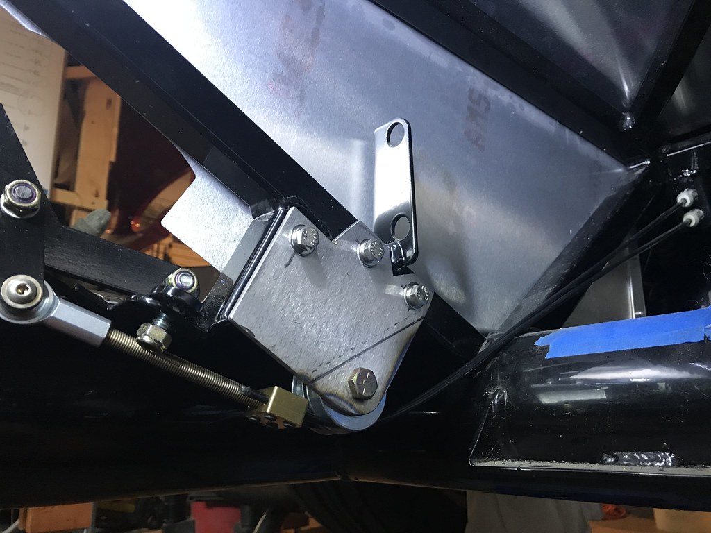
Untitled by John Ibele, on Flickr
You can see that the rear bracket bolt isn't tightened in this shot, but even so, there's clearance between it and the threaded rod, and the path that the rod takes to the pulley is low enough so it doesn't bind on the bracket either. When the cables are taut they don't rub against any part of the frame, the threaded rod doesn't bind, and the lever moves smoothly. Lastly, the lowest point on the assembly is still well above the frame bottom, which should keep it up and out of harm's way. The bracket is done and ready for paint.
This took a bit of time for bracket layout and fab, but the solution uses the basic setup provided with the kit and works very well. I'm very happy with the setup.
Last edited by John Ibele; 09-14-2021 at 02:05 PM.
MK4 #7838: IRS 3.55 TrueTrac T5z Dart 347
The drawing is from ~7th grade, mid-1970s
Meandering, leisurely build thread is
here


 Thanks:
  Likes:


 Reply With Quote

