-
FFR #9329 MK4 CAM-S Build
I received my kit in the summer of 2018, guess it's better to start the build thread late than never. The forum has been such a great source of information for me, hopefully something placed here can help someone else out. The build is aligning with the SCCA CAM-S class for autocross and will be heavily influenced by the fox body I've been able to co-drive (not mine) the last couple years.

The build plan:
- MKIV Base Kit
- 2015 IRS
- 363 Ford Crate Motor
- T5
- Mod Squad Front Suspension
I talked to Jim at FFR a couple times about possibly ordering the challenge car, in the end I chose the standard version for three main reasons. I wouldn't feel comfortable driving it around town without a helmet given the side roll bars, they appear to take a huge hit in resale compared to the normal model and it will not see road course use. Jim assured that the base chassis stiffness was more than sufficient and the forum consensus is the same.
Obviously, the best thing I did to prepare for the purchase was following this forum. I was also able to see several cars at national tour events and spend some quality time with the owners. They were very helpful and offered valuable insights while I rolled around on the ground taking pictures. We also took a long weekend and went to the factory. David and Dan answered every question and many more pictures were taken.
About the only item I would do differently is somehow not ordering the "base" kit. Although I was already subtracting items from the base kit and didn't need any additional parts from a full kit, the "base" kit is truly meant for a donor. Lots of things you don't need and don't realize to have removed. Spindle adapters, parts to chop up and use old donor gauges, etc... The real issue is the parts you do need that are set for donor use. Simple items like the front bulkhead aluminum panel pre-cut with multiple holes for donor pedals/MC that now need covering. And it came with the paper manual for donor build. I do have the complete kit manual online, but it is not as easy to glance at when dirty/sweaty/greasy.

Inventory was fairly uneventful with a few items identified that FFR got shipped quickly. Doing this has been extremely helpful later on. Going over the parts in detail and learning where they would be used has helped when it's time to pull them and finding the box/bag.
The body actually popped off fairly easily and is now hanging in the garage with a buck I made similar to others. The curves on the plan didn't seem to match very well, so I got a straight edge and mapped the curve height every inch and transferred that to the plywood. Cut it leaving a half inch for foam and it fits good.
I took a lot of pictures of the aluminum panels before disassembly and it still wasn't enough. You think when they are together it's obvious which panel was on top - oh how quickly the mind forgets.
Steve
Roadster #9329, 2015 IRS, 302, Holley Terminator Stealth, T5
-
I had purchased a 2015 GT rear subframe and disassembled the parts. Not sure what the better option is here, although it was half the price of new parts and at only 20K looked basically new - you don't use the majority of the parts and have to find a way to get rid of them. I have decided not to use the brakes, so willing to make a good deal on those if someone is interested. I started cutting the spindle using a sawzall like the directions and it was looking a little rough. I pulled out my old 9" band saw with fine blade and it went through it with ease. I've been using it for all my Al cutting now without issue.

Following EdwardB's suggestion I made pins for the alignment and the diff went in without too much drama. The rear suspension arms brought similar challenges that many mention about fitting into the tabs. I progressed through these actions until they fit properly:
- Used a spreader bolt to open the tabs so they were parallel or a little open. I fit the sleeve at each before installing to the arms.
- Even the smallest ball of weld splatter would stop the sleeve from going in, so I filed any imperfections if the sleeve was hanging up.
- For one or two, it was not possible to spread them enough to fit the sleeve. I used a disk sander to gently remove some length on the sleeve until it fit snug.

With everything in I made some rough settings and set the ride height at 3.5". Since I haven't decided on shocks yet, I bought some rod ends and round tube and made some adjustable rods for shock replacements. I think they will be handy as it locks the suspension in place, even when lifted. The whole setup looks great. I ran the numbers for roll center and camber gain and FFR did a good job back here.


Roadster #9329, 2015 IRS, 302, Holley Terminator Stealth, T5
-
Thanks for posting and starting this thread. Looking at those tires, I think this is going to be a fun build to follow.
-Steve
-
Not a waxer

Curious about where are you going to locate the approximately 300 pounds of ballast you'll need to make the minimum weight for CAM-S?
Jeff
-

Originally Posted by
Jeff Kleiner

Curious about where are you going to locate the approximately 300 pounds of ballast you'll need to make the minimum weight for CAM-S?
Jeff
Not sure I have all the answers here, but am making provisions underneath for additional weight along with some simple items that should help. I've already been going with the simple and heavier options at the low points, like steel sheet on the floorboards to create mounting points for the seats. I wasn't so keen on how the front section gave under my foot when climbing in anyway. Stuff that I could replace with lightweight versions if needed. The car that won nationals last year had to add less than 100lbs to make 2500, so I'm waiting to get a little further in the build before trying to guess the weight.
Steve
Roadster #9329, 2015 IRS, 302, Holley Terminator Stealth, T5
-
For the fuel cell, we have been using the Aeromotive 340 style. It is internally baffled and we haven't seen any issues of fuel starvation, even with some very low fuel levels. The 15 gallon was 10" tall, so no drop trunk. Instead of adding new points to the frame for strap mounting, I made a frame with straps that contains the tank and mounts to the chassis with 6 bolts which could be removed from the trunk area. Was only a couple lbs more and was an opportunity to weld something important. Still debating on whether to cut a hole in the side and have a filler neck added, we typically add directly to the tank with the large opening so you can see the level while pouring. Plenty of time to decide that later.

Started to template and cut aluminum that would fit around this. It can be a little crazy how much time one off fabrication can eat up. When a 6" piece with 4 bends that you already made 3 cardboard templates of doesn't fit because the bend just over 1/16" out of place, well, we've all been there.
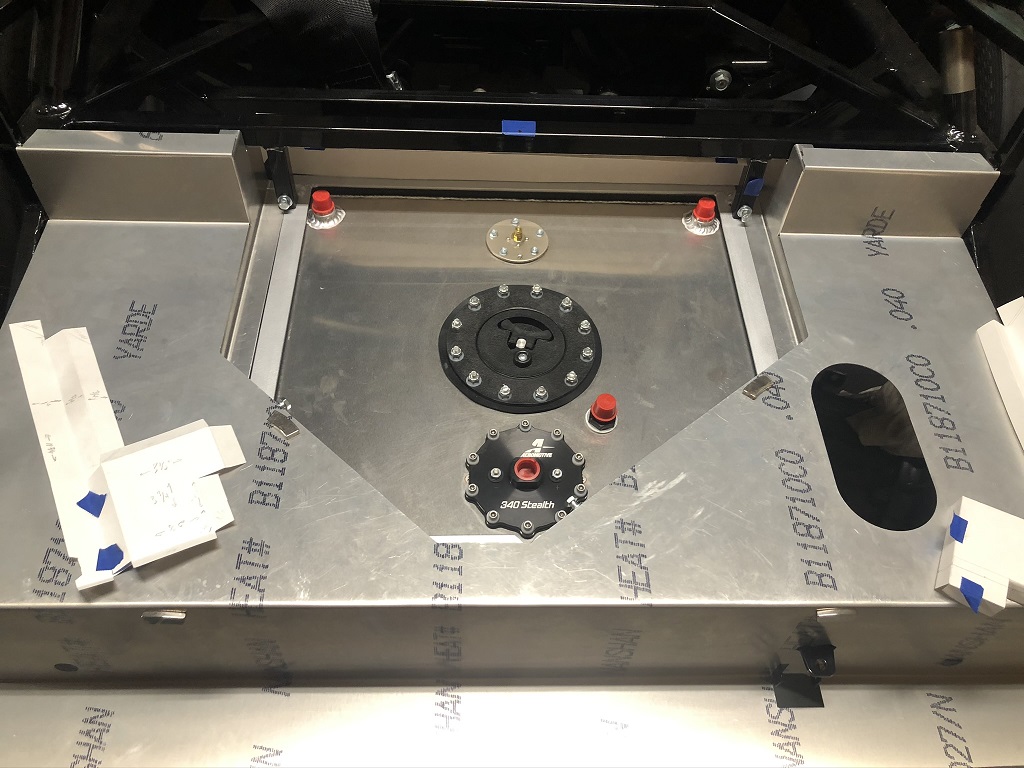
Still need to drill for rivets, but should keep the back sealed.

Steve
Roadster #9329, 2015 IRS, 302, Holley Terminator Stealth, T5
-

Steve >> aka: GoDadGo

Steve,
My Pop would often increase the thickness of the plate used in the bottoms of vessels he designed to minimize the need for ballast.
With that said, here are some weights of plates to help you do the same with your MK-4 which shows thickness vs pound per square foot.
3/16.....7.65
1/4.....10.20
5/16....12.80
3/8.....15.30
7/16....17.90
1/2.....20.40
Going with Iron Heads would pick up 40-45 pounds.
Hope this helps!
Steve
Last edited by GoDadGo; 08-31-2020 at 03:09 PM.
-
Post Thanks / Like - 0 Thanks, 1 Likes
-
Not a waxer
Steveseymore,
Don't forget about the extra 150 pounds you have to carry if you don't use a glass windshield. I'd like to run in the bigger field in CAM but that would mean adding weight and using less sticky tires which seems counterintuitive to me so I stick with XP. Either way I'm just out for fun with no aspirations of going to Nationals 
Jeff
-
Steve >> aka: GoDadGo
Here is some weight that will add power, but it won't be sitting very low in the chassis.
118 Pounds For Iron Eagle Assembled Heads:
https://2ovflq8a2if23r0004f29t3i-wpe...-Sheet-H29.pdf
I've got Dart Iron Eagle Heads and their SHP Block which both weigh more than the stock Chevy bits so adding this weight might offset things in a good way.
-
Originally Posted by
GoDadGo
Steve,
My Pop would often increase the thickness of the plate used in the bottoms of vessels he designed to minimize the need for ballast.
With that said, here are some weights of plates to help you do the same with your MK-4 which shows thickness vs pound per square foot.
3/16.....7.65
1/4.....10.20
5/16....12.80
3/8.....15.30
7/16....17.90
1/2.....20.40
Going with Iron Heads would pick up 40-45 pounds.
Hope this helps!
Steve
Thanks for the data, hopefully I'll be able to add the weight just where needed to get some good corner balancing.
Steve
Roadster #9329, 2015 IRS, 302, Holley Terminator Stealth, T5
-
Originally Posted by
Jeff Kleiner
Steveseymore,
Don't forget about the extra 150 pounds you have to carry if you don't use a glass windshield. I'd like to run in the bigger field in CAM but that would mean adding weight and using less sticky tires which seems counterintuitive to me so I stick with XP. Either way I'm just out for fun with no aspirations of going to Nationals
Jeff
Yes, it does seem a little counter intuitive, but there are quite a few options with good entrance numbers right now with the street touring type setups. At my current pace, a little worried the trend may change before I finish it. I'd be seeing you in XP at that point.
Steve
Roadster #9329, 2015 IRS, 302, Holley Terminator Stealth, T5
-
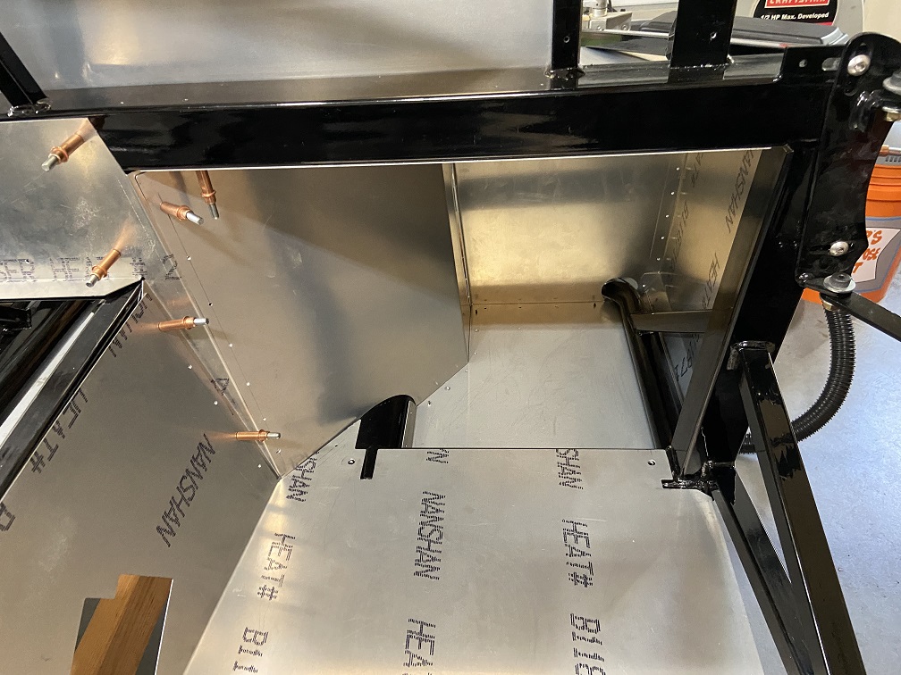
FFR #9329 MK4 CAM-S Build Footbox
Since the plan is to make use of a SBF in the engine bay, it seemed like there might be some space to be gained in the footbox. I've sat in several cars and while you don't really notice having your feet so far to the left, I thought try to lessen that feeling where it made sense. One thing that stood out was how the right footbox panel comes inward where my shin/knee rest. At first glance it appears the right footbox panel could be remade to gain some good width. I also found that the current panel width is not fully usable since the upper panel extends lower the further back you go. If the right panel was a little further out and the upper panel joint was kept well above the pedals, should make quite a difference. The pics below show some of the current lines/bends in red, with the planned changes in green. First pic shows how the upper panel impedes in the pedal area.


Before cutting anything up I wanted to validate some of this. I have a 289 that is waiting to go in my mustang, so it seemed like the perfect thing for test fitting. It was fun getting to see an engine set in the frame.

While in there with headers installed cardboard was used to see how much spacing would still be available with the mods. Looks good, so hoping there's not something I'm missing.

I really don't feel like changing the passenger side, but there appears quite a bit of room available there. Plenty of scope creep already, so hoping to leave that one alone.

Steve
Roadster #9329, 2015 IRS, 302, Holley Terminator Stealth, T5
-
I made a similar modification and it was probably the best thing I did to the car. Very happy with the extra room. Small gain but I'm 6'6" so it was a great improvement.

-Steve
-
Post Thanks / Like - 0 Thanks, 1 Likes
-
Steve - Yes, yours was one of the posts I saw that made it look promising - well executed.
Roadster #9329, 2015 IRS, 302, Holley Terminator Stealth, T5
-
Driver Footbox Updated
So a few panel templates, cutting and bending and we have this:

It was difficult to get a good template as cardboard was too thick to model all the bends and poster board was too flimsy for the large area. In the end I used poster board with scrap aluminum taped to the edges to get the final template. I don't have the pedals in this pic, but the main section is wider and the inset is now above my toes.
Been working on fab and drilling throughout the footboxes and cockpit, can't wait to get all these little holes finished and move on to other assembly.
Steve
Roadster #9329, 2015 IRS, 302, Holley Terminator Stealth, T5
-
Post Thanks / Like - 0 Thanks, 2 Likes
-
Cockpit Fitting Complete
So it's fit/cut/bend/drill and repeat, the cockpit is now complete. Realizing now I'm may be doing these panels the hard way. I hoped to have all panels lay flush (no panel bend over edges/corners) not realizing how much time every little adjustment takes. Too late now although I may be the only person who ever notices. There is an occasional hole or two in the wrong place and a few panels with the wrong overlap, but they can be removed/installed easily with clecos - so ready to move on to other items.
The rear wall to tunnel corners were the most challenging and didn't want to be in front of the lower tabs with the tunnel side tab behind. I ended up removing 1/8" from the tunnel side and it went without as much bending.

You may notice I also had to switch the sill plates from left to right as my seat plate extended to the mount area. It looks really clean this way as the front and lower flange are to the outside. I can't image anyone pressing on the lower portion given the location, and put an external tab which seems plenty stiff. As one of my non-overlap decisions, the sill and rear outer corner are puzzle fit so everything mounts flush. The seat belt mount puts the lower hole higher than planned (tool clearance), but looks good.


I did put one panel in the passenger footbox below the floor instead of above and didn't notice till getting to the top and seeing a gap. All the other holes are already drilled so a little fake bend at the top to somewhat recover. Per the theme, no one else will ever know anyway.
I am wondering how the rivets should be installed between the inner footbox wall and lower firewall/tunnel vertical section. It seems these will be visible from the engine bay, does the crush end go to the inside and then covered by carpet?
Steve
Roadster #9329, 2015 IRS, 302, Holley Terminator Stealth, T5
-
Senior Member

Originally Posted by
steveseymore
I am wondering how the rivets should be installed between the inner footbox wall and lower firewall/tunnel vertical section. It seems these will be visible from the engine bay, does the crush end go to the inside and then covered by carpet?
Steve
Looking good. Where the rivets are visible (e.g. in the engine compartment, in the wheel wells, etc.) I always put the head of the rivet on the visible side, and the crush end on the inside. If you use the right rivet length for the thickness, the crush end is plenty low enough to be covered by insulation (which you're planning, right?) and carpet.
Build 1: Mk3 Roadster #5125. Sold 11/08/2014.
Build 2: Mk4 Roadster #7750. Sold 04/10/2017.
Build Thread
Build 3: Mk4 Roadster 20th Anniversary #8674. Sold 09/07/2020.
Build Thread and
Video.
Build 4: Gen 3 Type 65 Coupe #59. Gen 3 Coyote. Legal 03/04/2020.
Build Thread and
Video
Build 5: 35 Hot Rod Truck #138. LS3 and 4L65E auto. Rcvd 01/05/2021. Legal 04/20/2023.
Build Thread. Sold 11/9/2023.
-
Originally Posted by
edwardb
Looking good. Where the rivets are visible (e.g. in the engine compartment, in the wheel wells, etc.) I always put the head of the rivet on the visible side, and the crush end on the inside. If you use the right rivet length for the thickness, the crush end is plenty low enough to be covered by insulation (which you're planning, right?) and carpet.
Perfect, thanks. Yes, planning to follow your lead with the lizard skin for the panels. Turns out the mustang above also has this on the firewall and floor. The site specifically says spray on, but he did his with a roller. Anyone else used another method beside spray for application? I assume the manufacturer knows what's best.
Steve
Roadster #9329, 2015 IRS, 302, Holley Terminator Stealth, T5
-
Rear Cockpit Wall Top
In looking at some other posts, it appears the top edge of the rear cockpit wall should be riveted to the 3/4" top bar. Mine has the factory bend so it is forward about 3/4" from the bar which allows the rear wall and rear corner panels to mate perfectly on the factory bends. If I pull the wall back to the bar, the bar actually blocks about 1/4" of the seat belt holes making it too small for the buckles to pass through and the mating panels spread.


I don't remember ever seeing a post on this - is the rear wall intended to be flush to the highest bar? I don't see any way it could be higher to clear the seat belt holes as the lower tab has to mate with the floor.
Steve
Roadster #9329, 2015 IRS, 302, Holley Terminator Stealth, T5
-
Senior Member
Yes, that rear wall should be against the 3/4" tube. Yes, that's correct the 3/4" tube goes through the opening as in your pictures. That's to keep the harness from rubbing against the sharp edge of the aluminum. Along with adding serrated grommeting around the remaining opening. To install the harness, you need to remove the mounting tab and slider from the harness, feed the harness through the opening, and the replace the mounting tab and slider onto the harness. All is shown in the build manual BTW.
Last edited by edwardb; 01-03-2021 at 10:57 AM.
Build 1: Mk3 Roadster #5125. Sold 11/08/2014.
Build 2: Mk4 Roadster #7750. Sold 04/10/2017.
Build Thread
Build 3: Mk4 Roadster 20th Anniversary #8674. Sold 09/07/2020.
Build Thread and
Video.
Build 4: Gen 3 Type 65 Coupe #59. Gen 3 Coyote. Legal 03/04/2020.
Build Thread and
Video
Build 5: 35 Hot Rod Truck #138. LS3 and 4L65E auto. Rcvd 01/05/2021. Legal 04/20/2023.
Build Thread. Sold 11/9/2023.
-
Thanks for the explanation. I looked at the real panel install page several times and was sure it didn't have rivets there, but of course looking again I see two outside temp screws and faint shadows for holes along the top. I guess it's like measuring, read twice - install once.
Steve
Roadster #9329, 2015 IRS, 302, Holley Terminator Stealth, T5
-
any updates on your build?
-
Well, a little gap in updates that I will try to rectify going forward. A stall opened up at Mod Squad last spring and they were nice enough to let me move the car and let me work on it there. If you think it's hard to make time for car work in the garage - try to do the work on the other side of town.
I'll start by saying that the front suspension and spindles that FFR has designed produce good geometry and can be set up well for both street and track. I was looking to have more flexibility and ease in adjustments, which eventually drove the following. Certainly not required, but allows for quick adjustment of kingpin, caster, camber, bump, ackerman and anti-dive using circle track influenced parts. It also allows both upper and lower arm mounting height changes. Most of the time was spent with measurement and mock up, the actual execution ended up being fairly straightforward.
As with many great changes - it started with a sawzall and the wheel of death. The lower arm mounting height was within the frame and being on the outside would result in too short of an arm. In the end, making a channel in the frame for an inner mounted arm to move through created good geometry. Supports were added to mitigate any loss of strength.
Cut all the mounts and channels:

Lots of mock up measurements:

If you have the right equipment, you can make some cool stuff:
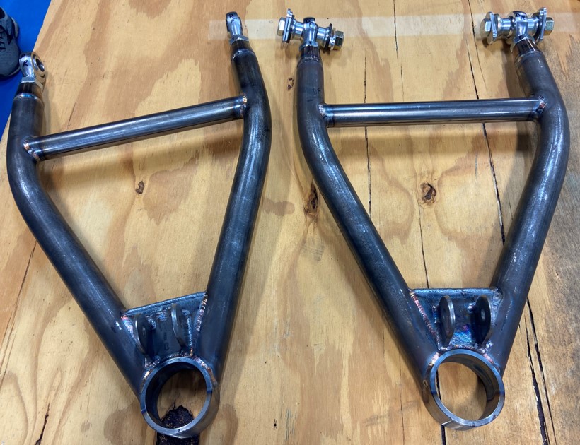
If you see any funky welds, they are mine. I let the experts do the important stuff:
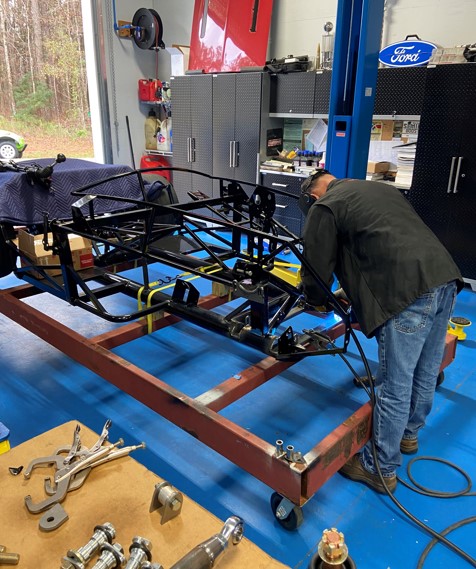
Test fit:

We were able to roll it off the trailer and into the garage after multiple months:
Roadster #9329, 2015 IRS, 302, Holley Terminator Stealth, T5
-
Post Thanks / Like - 0 Thanks, 1 Likes
-
Sway Bars
I like the setup and quality of Speedway Engineering's sway bars and they will be on both ends. There was a gap in time between the plan and installation and I honestly can't remember the full rationale for the install locations. I know in the front it really needs to be in the tow hook area but I didn't want to mess with any further cut/weld items. In the interest of forward progress they will get mounted per original sketches.
The rear is mounted in the trunk area and should be easy to access for adjustment.

For the front, current compromise has the support brackets connect to existing holes and have the bar above the lower arm. (The arms aren't shown since they are out having the ends bent)

Roadster #9329, 2015 IRS, 302, Holley Terminator Stealth, T5
-
-
Post Thanks / Like - 0 Thanks, 1 Likes
-
Pedal Box and Clutch Stop
Tilton pedals and MCs are installed in footbox. Routed the rear hardline inside the firewall and through the floor to the outside of the 4" tube. I added a tab to the front of the drivers footbox tube so a 1/2" square cross bar could be bolted from the tab to the throttle mount. A bolt was then added for use as a clutch pedal stop.


Roadster #9329, 2015 IRS, 302, Holley Terminator Stealth, T5
-
-
Roll Bars
I actually don't remember if I requested the 2" dia roll bars, but that is what I got and definitely prefer the look on the car. Unfortunately they require a 1-1/14" tube with 1/4" wall thickness spacer between the mounts and bars. So more metal to drill, but I like the look. Definitely doesn't have that thin/tall look that the 1-1/2" tubes have. The fit was fairly straightforward with only minor shaping of the mating end of the back tubes so they fit without gap around the perimeter. Of course there was a crazy amount of time trying to hold the drill straight while leaning into it, seems standard work at this point. Almost feels like I could have designed a two prong fixture that held the drill and went around the back of the tube to pull it into the tube in the amount of time I spent holding that drill.


Roadster #9329, 2015 IRS, 302, Holley Terminator Stealth, T5
-
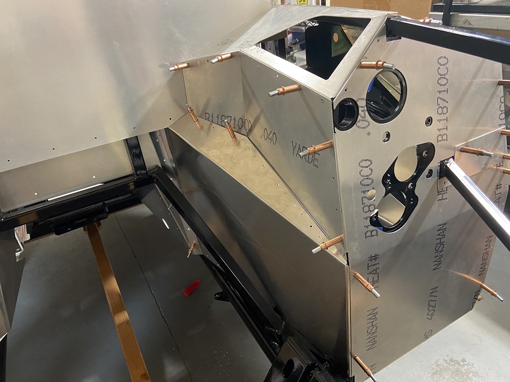
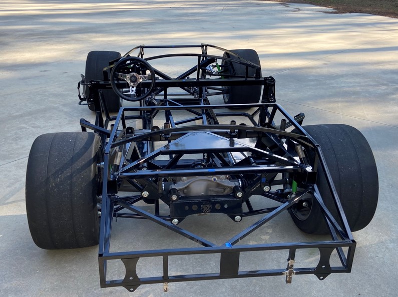
Body Fitting
The first body fit showed how tight the rear sides and lower trunk were. I should have left the bulb seal off the rear sides (I did on the lower floor) for this fitting, a couple spots at the rear were completely in contact and the body was basically just even at the door latch. The rear sides now need new bulb seal. After removing around 3/8" from the rear lower panel and trimming the rear sides to the curve of the body, everything else looked as expected. The body is just forward of the door and the dash appears it will be clearanced if all the highs are knocked down and the gap is evened out. Same for the rear cockpit opening.

A section of hose which fit tight in the front mounting holes was used around the mounting bolts for fitment. This will be replaced with the Metro EX17B grommet kit with aluminum tubes cut to length. The front was on the verge of alignment with the quick jack through bolts at the end of the available slot. A 6' board was used to tweak the front mounting rail just a bit and all bolts are now in the center of the slot with the body centered to the suspension mounts. Put the wheels on and verified centered on tires also since suspension is already aligned. The front wheel openings will be widened to accommodate the tire width and track.

I tried to check as many items as possible while the body was installed. I marked as best as possible on the underside where it looked like the roll bars will go. Also marked where the frame windshield mounts would protrude. I paid for the FFR precuts, and my marks just showed the sides that may need some enlargement. Passenger side holes apparently aren't part of the standard cut outs, but should go quick. Installed all the lights and markers with simple clearancing of factory cuts and adding mounting holes. I didn't have the engine in, so couldn't do much with the exhaust cutouts yet. I'll pull it off and make all the marked cuts and probably have to do it a couple more times to get the final clearances.
Roadster #9329, 2015 IRS, 302, Holley Terminator Stealth, T5


 Thanks:
  Likes:


 Reply With Quote

