Boig Motorsports

Visit our community sponsor

Thanks Thanks:  8
Likes Likes:  31
Page 5 of 26 FirstFirst ... 3456715 ... LastLast
Results 161 to 200 of 1012

Thread: Frank's 818R build

  1. #161
    Senior Member Frank818's Avatar
    Join Date
    Jun 2013
    Location
    QC, Canada
    Posts
    5,732
    Post Thanks / Like
    Remounting the hard line bracket on the front side of the tube. That's where I fitted mine after test fitting with my custom length braided lines.
    Frank
    818 chassis #181 powered by a '93 VW VR6 Turbo GT3582R
    Go-karted Aug 5, 2016 - Then May 19+21, 2017
    Tracked May 27/July 26, 2017
    Build time before being driveable on Sep 27, 2019: over 6000h
    Build Completed Winter 2021

  2. #162
    Senior Member Pearldrummer7's Avatar
    Join Date
    Feb 2014
    Location
    Asheville, NC
    Posts
    1,230
    Post Thanks / Like
    Quote Originally Posted by Frank818 View Post
    Remounting the hard line bracket on the front side of the tube. That's where I fitted mine after test fitting with my custom length braided lines.
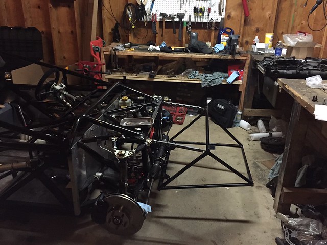
    I did exactly that! It fit just right now. Tightened up the brakes and I'm just about ready for wheels!


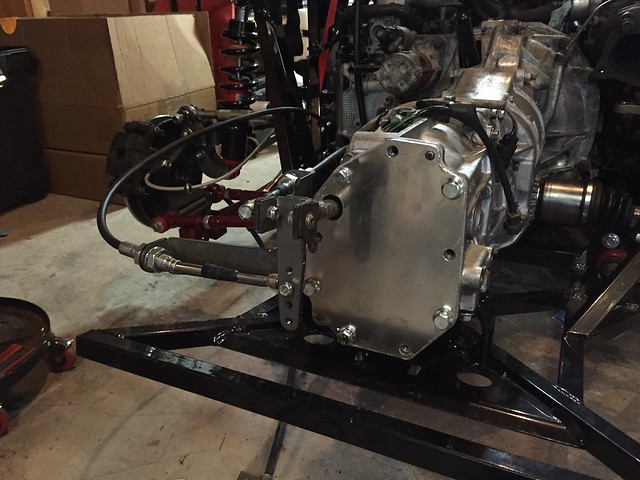
    Also got into some shifter work this weekend. Man, those cables are cool!

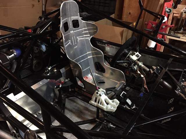
    Test fit with the seat so I can pretend to slam gears

  3. #163
    Senior Member Pearldrummer7's Avatar
    Join Date
    Feb 2014
    Location
    Asheville, NC
    Posts
    1,230
    Post Thanks / Like
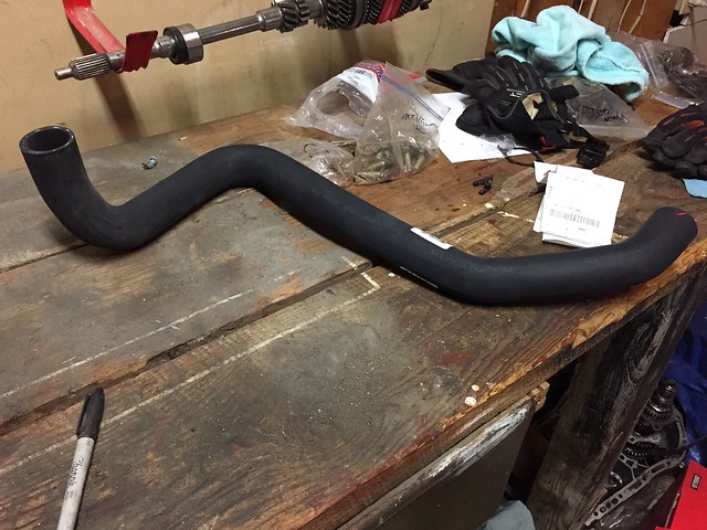
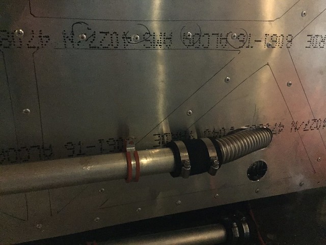
    Also found this gem of a coolant hose in Advanced Auto. It was $13 I think, and it's so long! Has some cool bend in it, too. I'm using this to reroute my coolant lines on the passenger side of the car.


  4. #164
    Senior Member Frank818's Avatar
    Join Date
    Jun 2013
    Location
    QC, Canada
    Posts
    5,732
    Post Thanks / Like
    Happy to help, Frank, it's great when you say something and it helps someone else.

    Those are the FFR supplied shifter cables?
    Frank
    818 chassis #181 powered by a '93 VW VR6 Turbo GT3582R
    Go-karted Aug 5, 2016 - Then May 19+21, 2017
    Tracked May 27/July 26, 2017
    Build time before being driveable on Sep 27, 2019: over 6000h
    Build Completed Winter 2021

  5. #165
    Senior Member Pearldrummer7's Avatar
    Join Date
    Feb 2014
    Location
    Asheville, NC
    Posts
    1,230
    Post Thanks / Like
    Quote Originally Posted by Frank818 View Post
    Happy to help, Frank, it's great when you say something and it helps someone else.

    Those are the FFR supplied shifter cables?
    It's definitely great when that happens! You're a huge help, as are most people on this forum.

    Those are the supplied cables. Are you using them or do you have to do something different?

  6. #166
    Senior Member Frank818's Avatar
    Join Date
    Jun 2013
    Location
    QC, Canada
    Posts
    5,732
    Post Thanks / Like
    I don't know if I can use the FFR cables with the K-Tuned shifter and I didn't check if length was working with my engine, but I already bought a custom length set from Wayne for race cables, apparently people like the feeling of these cables. Bought them a long time ago but could only provide the length recently.
    Frank
    818 chassis #181 powered by a '93 VW VR6 Turbo GT3582R
    Go-karted Aug 5, 2016 - Then May 19+21, 2017
    Tracked May 27/July 26, 2017
    Build time before being driveable on Sep 27, 2019: over 6000h
    Build Completed Winter 2021

  7. #167
    Senior Member Pearldrummer7's Avatar
    Join Date
    Feb 2014
    Location
    Asheville, NC
    Posts
    1,230
    Post Thanks / Like
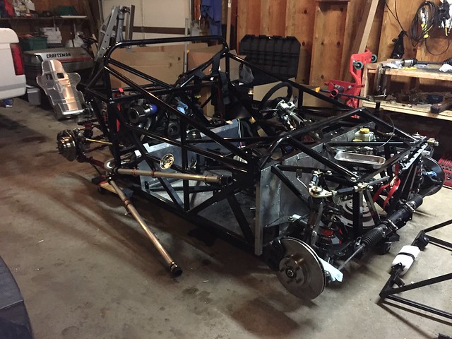
    Coolant lines and the nose are on! Coolant lines are on the passenger side because racecar (and ballast). I looked at the nose a few times, only to realized that it doesn't need a bracket and isn't the same as in the manual. No mount/bracket necessary; it just bolts right up.

    Also, my pack of 8 3/8"-16 x 1" bolts was down a bolt. Seems to be the story of this build for me! (one bolt short)


  8. #168
    Senior Member
    Join Date
    Sep 2013
    Location
    Chicago, IL
    Posts
    571
    Post Thanks / Like
    Are your upper radiator support brackets backwards or did you swap sides? Not sure it really matters, but I thought the scalloped holes in the angle bar go to the outside.

    Minor thing, but mostly I'm just jealous that you're making progress. =)

    Best,
    -j
    "Weight transfer is the enemy."

    Executive Director
    The Community Garage

  9. #169
    Senior Member Tamra's Avatar
    Join Date
    Apr 2014
    Location
    Shelton, CT
    Posts
    1,011
    Post Thanks / Like
    Will the coolant lines both fit through the dead pedal area, by routing them both on the passenger side? Any issues you've ran into doing it this way? Seems like a great idea.

    EDIT: never mind, you have an R. Do you know of anyone who's done this with an S?
    Last edited by Tamra; 12-12-2014 at 11:06 AM.
    Tamra
    Building 818SR #297 picked up 10/25/14 with Andrew (xxguitarist)
    First start 12/21/14, First "drive" 1/17/15
    First Dyno at EFI Logics 3/7/15- 310whp at 15psi for break in, full spool by ~3500rpm!
    First autocross 3/29/15
    1st Registered 818 in Connecticut 7/24/2015. 9 months - 1 day from kit pickup!

  10. #170
    Senior Member Pearldrummer7's Avatar
    Join Date
    Feb 2014
    Location
    Asheville, NC
    Posts
    1,230
    Post Thanks / Like
    Quote Originally Posted by Tamra View Post
    Will the coolant lines both fit through the dead pedal area, by routing them both on the passenger side? Any issues you've ran into doing it this way? Seems like a great idea.

    EDIT: never mind, you have an R. Do you know of anyone who's done this with an S?
    It's not an issue with the R(as you mentioned) however, I bet if you just stuck the flex tube through that spot without committing to anything you could see if it fits on the S. I would imagine it fits, just at a glance. I think I'm still running mine through that area.

    Only issues so far are that it's:
    1) a little longer of a run
    2) the bend is a little more extreme coming from the lower coolant line at the block. I kind of got around that by buying a different flexible hose (from some GMC truck at Advanced Auto) and using that instead of the WRX one.


    Quote Originally Posted by Santiago View Post
    Are your upper radiator support brackets backwards or did you swap sides? Not sure it really matters, but I thought the scalloped holes in the angle bar go to the outside.

    Minor thing, but mostly I'm just jealous that you're making progress. =)

    Best,
    -j
    Thanks, J! I did swap them and they fit a little nicer now. Good eye!

  11. #171
    Senior Member FFRSpec72's Avatar
    Join Date
    Feb 2011
    Location
    Kirkland, WA
    Posts
    2,256
    Post Thanks / Like
    Quote Originally Posted by Pearldrummer7 View Post
    Coolant lines and the nose are on! Coolant lines are on the passenger side because racecar (and ballast). I looked at the nose a few times, only to realized that it doesn't need a bracket and isn't the same as in the manual. No mount/bracket necessary; it just bolts right up.
    I had the issue of getting the wrong steering rack bracket, as the nose mount bolts and the steering rack bolts were on top of each other, with the new rack bracket and single spacer all went well
    Tony Nadalin
    2022 SOVREN Championship
    2018 SOVREN Big Bore Champion
    2015 SCCA Oregon Region VP3 Champion
    2012 ICSCC ITE Class Champion
    FFR MkII Challenge Car, Spec Racer, Street Legal, SCCA, ICSCC and NASA Racing

  12. #172
    Senior Member Pearldrummer7's Avatar
    Join Date
    Feb 2014
    Location
    Asheville, NC
    Posts
    1,230
    Post Thanks / Like
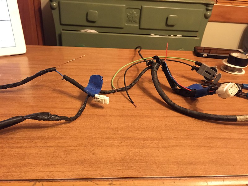
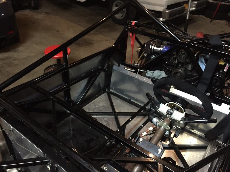
    Since it's now cold in the garage, I'm doing some stuff that's possible inside the house.

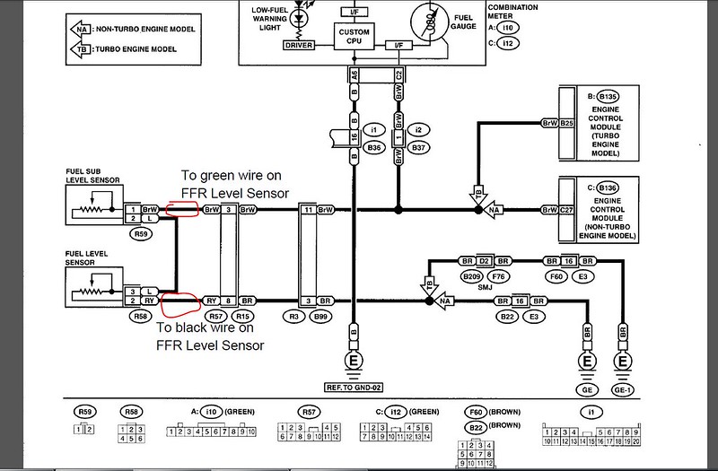
    Splicing the fuel pump and level sensor right now. These are the connections I'm planning to make for them:


    Here's a live-action shot of the connectors for the level sensor:

  13. #173
    Senior Member
    Join Date
    May 2012
    Location
    Suisun City, CA
    Posts
    851
    Post Thanks / Like
    Interesting. What year/model is that schematic from? It appears to not have a fuel pump controller?
    818S - #67 (SOLD IT!)
    Delivered: 18 November 2013
    Go Karted: 29 December 2013
    Titled/Registered: 28 March 2014
    Finished: NEVER!
    341 hp @ 4844 RPM / 389 tq @ 3717 RPM

  14. #174
    K3LAG's Avatar
    Join Date
    May 2013
    Location
    Greensburg, PA
    Posts
    552
    Post Thanks / Like
    Looks like it's an NA schematic. Only the turbo cars have the fuel pump controller.

    Larry

  15. #175
    Senior Member Pearldrummer7's Avatar
    Join Date
    Feb 2014
    Location
    Asheville, NC
    Posts
    1,230
    Post Thanks / Like
    Quote Originally Posted by JeromeS13 View Post
    Interesting. What year/model is that schematic from? It appears to not have a fuel pump controller?
    Quote Originally Posted by K3LAG View Post
    Looks like it's an NA schematic. Only the turbo cars have the fuel pump controller.

    Larry
    *facepalm*

    I noticed that and immediately updated my wiring/harness thread, and not this thread. A game of Settlers of Catan got in the way (for the last 4 hours...I won, though! ) of me correcting this.

    I'm not at all sure where I'm splicing the pump yet. Does anyone have any suggestions?

  16. #176
    Senior Member Pearldrummer7's Avatar
    Join Date
    Feb 2014
    Location
    Asheville, NC
    Posts
    1,230
    Post Thanks / Like
    AWESOME present from my Reddit Secret Santa:

    http://imgur.com/djXUh0D

    Very cool, especially since I didn't have a shift knob on the car yet. This one's relatively light and a good size, too.


    Hope everyone on the forums had a great holiday!

  17. #177
    Senior Member Frank818's Avatar
    Join Date
    Jun 2013
    Location
    QC, Canada
    Posts
    5,732
    Post Thanks / Like
    Nice chrome knob.
    Frank
    818 chassis #181 powered by a '93 VW VR6 Turbo GT3582R
    Go-karted Aug 5, 2016 - Then May 19+21, 2017
    Tracked May 27/July 26, 2017
    Build time before being driveable on Sep 27, 2019: over 6000h
    Build Completed Winter 2021

  18. #178
    Senior Member Pearldrummer7's Avatar
    Join Date
    Feb 2014
    Location
    Asheville, NC
    Posts
    1,230
    Post Thanks / Like
    Quote Originally Posted by Frank818 View Post
    Nice chrome knob.
    Thanks, Frank!

  19. #179
    Senior Member wleehendrick's Avatar
    Join Date
    Jul 2012
    Location
    Encinitas, CA
    Posts
    1,653
    Post Thanks / Like
    Blog Entries
    2
    Quote Originally Posted by Frank818 View Post
    Nice chrome knob.


    Looks good, Frank!


    That__s_What_She_Said_by_J_Bob.png

  20. #180
    Senior Member Pearldrummer7's Avatar
    Join Date
    Feb 2014
    Location
    Asheville, NC
    Posts
    1,230
    Post Thanks / Like
    Quote Originally Posted by wleehendrick View Post
    Haha this is fantastic. I don't use Michael Scott flavored memes nearly enough.


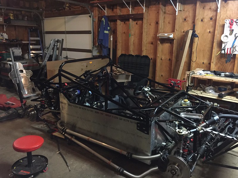
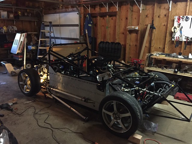
    Finished my side paneling:


  21. #181
    Senior Member Pearldrummer7's Avatar
    Join Date
    Feb 2014
    Location
    Asheville, NC
    Posts
    1,230
    Post Thanks / Like
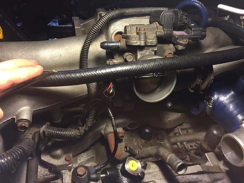
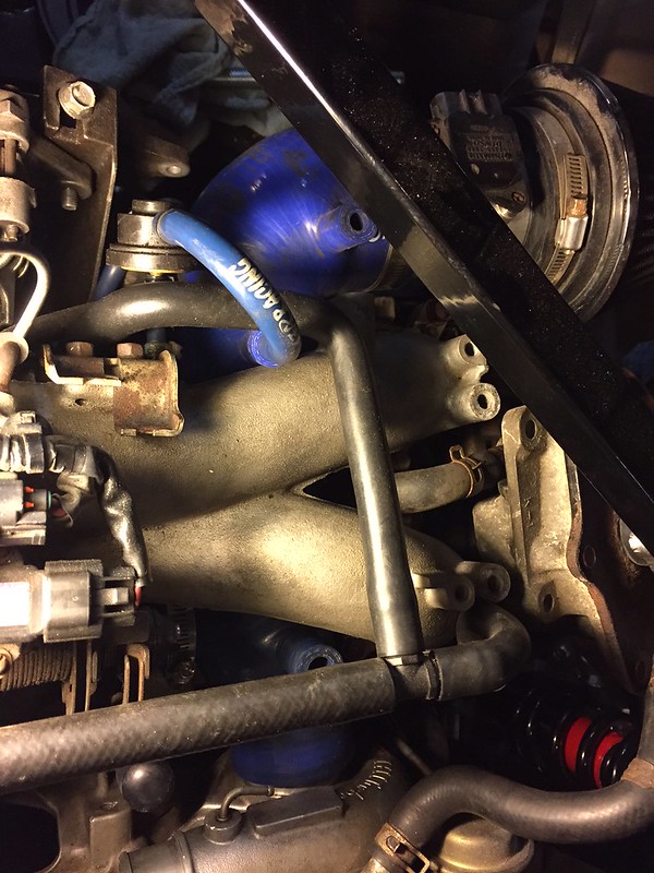
    So, I got rid of that pesky coolant path running around the throttle body. Slightly colder air temps, here I come! Not shown in the pic is that I repurposed the original (photo right) hose by attaching the throttle side to the right coolant line and the right side to the left coolant line.


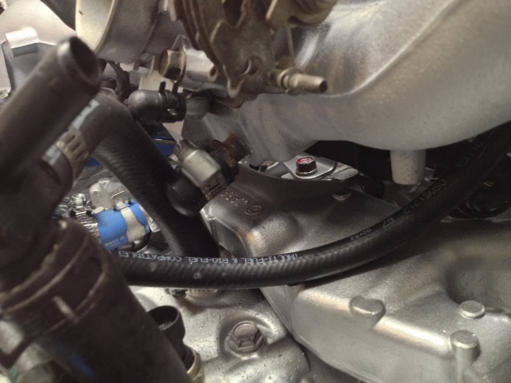
    My friends and I were discussing some of the logistics of PCV vs. VTA vs. catch can, and it turns out I will at least be plugging these two holes on the intake:


    I hear VERY mixed reviews on deleting the PCV system. Our thought was to plug all but the "main" crankcase outlet, and have that one vent to atmosphere through a filter. This way, I'm never feeding vaporized oil into my intake, but can still keep nearly neutral pressure in my crankcase. Please explain to me why this won't work.

  22. #182
    Senior Member Tamra's Avatar
    Join Date
    Apr 2014
    Location
    Shelton, CT
    Posts
    1,011
    Post Thanks / Like
    You want the heads and both block spots breathing. The ideal way is to run the center crank vent back into an unbaffled fitting on the heads (you have to put a new fitting on the 205 heads to do this; the 257 heads already have the fitting and that is how it is run from the factory, minus the catch cans), and then run the baffled vent on the heads to a T with each other and a catch can, and run the baffled crank to a catch can. Then you can get vacuum from wherever you want or vent to atmosphere.

    We did not drill out the heads before assembly, so what we are doing is running the two block spots together into a catch can, and the two baffled ports on the heads together into a catch can, and having both pull vacuum from the exhaust with a venturi. We will wind up with a bit of oil coming out of the center crank vent because it is not baffled but oh well.

    Here's a photo of ours. You can see the two hoses running into the T (we reused the original one). The top port that is open in this photo now has a hose on it running to a catch can:
    Tamra
    Building 818SR #297 picked up 10/25/14 with Andrew (xxguitarist)
    First start 12/21/14, First "drive" 1/17/15
    First Dyno at EFI Logics 3/7/15- 310whp at 15psi for break in, full spool by ~3500rpm!
    First autocross 3/29/15
    1st Registered 818 in Connecticut 7/24/2015. 9 months - 1 day from kit pickup!

  23. #183
    Senior Member Pearldrummer7's Avatar
    Join Date
    Feb 2014
    Location
    Asheville, NC
    Posts
    1,230
    Post Thanks / Like
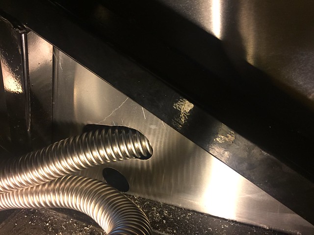
    Slotted the coolant hose pass through so it was at less of an angle. I think it's a cool idea. Anyone see a reason this is not a good move?


  24. #184
    Senior Member Pearldrummer7's Avatar
    Join Date
    Feb 2014
    Location
    Asheville, NC
    Posts
    1,230
    Post Thanks / Like
    Quote Originally Posted by Tamra View Post
    You want the heads and both block spots breathing. The ideal way is to run the center crank vent back into an unbaffled fitting on the heads (you have to put a new fitting on the 205 heads to do this; the 257 heads already have the fitting and that is how it is run from the factory, minus the catch cans), and then run the baffled vent on the heads to a T with each other and a catch can, and run the baffled crank to a catch can. Then you can get vacuum from wherever you want or vent to atmosphere.

    We did not drill out the heads before assembly, so what we are doing is running the two block spots together into a catch can, and the two baffled ports on the heads together into a catch can, and having both pull vacuum from the exhaust with a venturi. We will wind up with a bit of oil coming out of the center crank vent because it is not baffled but oh well.

    Here's a photo of ours. You can see the two hoses running into the T (we reused the original one). The top port that is open in this photo now has a hose on it running to a catch can:
    I really like this. I will be doing exactly this set up with a catch can I think. I didn't drill out a spot for a fitting on the 205 heads I have, so I'm not left with a lot of options.

  25. #185
    Senior Member Pearldrummer7's Avatar
    Join Date
    Feb 2014
    Location
    Asheville, NC
    Posts
    1,230
    Post Thanks / Like


    Popped the WRX wheels on it, just to see. Torqued suspension to spec beforehand. They definitely don't fit (+48mm offset) :lol:

  26. #186
    Senior Member Bob_n_Cincy's Avatar
    Join Date
    Sep 2012
    Location
    Cincinnati OH
    Posts
    3,910
    Post Thanks / Like
    Quote Originally Posted by Pearldrummer7 View Post
    Popped the WRX wheels on it, just to see. Torqued suspension to spec beforehand. They definitely don't fit (+48mm offset) :lol:
    What size tires and where did they not fit?
    818S #22 Candy Blue Frame, Front Gas Tank, 2.5L Turbo, Rear radiator, Shortened Transmission, Wookiee Compatible, Console mounted MR2 Shifter, Custom ECU panel, AWIC soon
    My Son Michael's Turbo ICE Build X22 http://thefactoryfiveforum.com/showt...rts-818S-Build
    My Electric Supercar Build X21 (on hold until winter) http://thefactoryfiveforum.com/showt...e-Build-Thread

  27. #187
    Senior Member C.Plavan's Avatar
    Join Date
    Mar 2011
    Location
    Clovis, Ca
    Posts
    2,225
    Post Thanks / Like
    Quote Originally Posted by Pearldrummer7 View Post
    Slotted the coolant hose pass through so it was at less of an angle. I think it's a cool idea. Anyone see a reason this is not a good move?


    It will be fine as long as you place rubber around the holes- The metal will eventually rub through and give you a coolant leak. You can just get some fuel hose, cut it length wise and put it over the cut edges as a rubber gasket.
    Thanks- Chad
    818R-SOLD!!!- Go Karted 7/20/14/ Officially raced NASA ST2- 2/28/15
    2016 Elan NP01 Prototype Racecar Chassis #20
    1969 Porsche 911ST Vintage Race Car
    1972 Porsche 911T (#'s matching undergoing nut & bolt resto in my garage)

  28. #188
    Senior Member Pearldrummer7's Avatar
    Join Date
    Feb 2014
    Location
    Asheville, NC
    Posts
    1,230
    Post Thanks / Like
    Quote Originally Posted by Bob_n_Cincy View Post
    What size tires and where did they not fit?
    It's the +48mm offset that doesn't work. Rubs the rear links pretty bad. They're 17x8 wheels with 235/45 Z2's on them (for the WRX I daily drive)

    Quote Originally Posted by C.Plavan View Post
    It will be fine as long as you place rubber around the holes- The metal will eventually rub through and give you a coolant leak. You can just get some fuel hose, cut it length wise and put it over the cut edges as a rubber gasket.
    Oh good call, Chad. Thanks for that.

  29. #189
    Harley818's Avatar
    Join Date
    Jan 2014
    Location
    Vancouver BC
    Posts
    788
    Post Thanks / Like
    From what I read on the forum as well as on the Impreza forum I'm going to use two catch cans. One takes the two lines from the valve covers, through the first catch can and into a port on the intake, the other takes the main crankcase vent through the second catch can to the port on the intake. They say to run them separately as they have different rates of flow that you don't want to mix.
    I'm new to the Subaru engines so I hope this works out.
    Anyone see any problems with this set up?

  30. #190
    Tazio Nuvolari wannabe Scargo's Avatar
    Join Date
    Nov 2013
    Location
    south-central CT
    Posts
    1,611
    Post Thanks / Like
    Harley818, You've left out a lot of details. Why are you wanting catch-cans? I'm not familiar with your goals for the car. Mainly, what happens to what you are catching?
    I don't know how many dissertations and warnings I've put out about this, but if you run more than stock boost (and a few other factors) you run a high risk of busting ring-lands of stock pistons if oil from the catch-cans ever finds its way into the intake. You may have inspection/emissions issues to deal with, or no, but if you are modding it to a VTA (vent to atmosphere) setup you should consider letting it go back into the engine and not build up in a can.
    I hope we don't suck the oxygen out of Frank's thread with a long-winded discussion on this topic right here. Why not ask it on your thread? I'll bet you a dollar to a donut there's already a thread started on the subject.

  31. #191
    818 builder metalmaker12's Avatar
    Join Date
    Mar 2012
    Location
    Exeter R.I
    Posts
    2,834
    Post Thanks / Like
    Blog Entries
    1
    Crawford or Perrin Aos is all that's truely proven to work correctly in all conditions with little maintance period.
    http://www.maperformance.com/blog/be...rrin-crawford/
    Last edited by metalmaker12; 01-17-2015 at 08:02 AM.
    818S frame #13 Jdm version 8 ej207

  32. #192
    Senior Member Pearldrummer7's Avatar
    Join Date
    Feb 2014
    Location
    Asheville, NC
    Posts
    1,230
    Post Thanks / Like
    Quote Originally Posted by Harley818 View Post
    From what I read on the forum as well as on the Impreza forum I'm going to use two catch cans. One takes the two lines from the valve covers, through the first catch can and into a port on the intake, the other takes the main crankcase vent through the second catch can to the port on the intake. They say to run them separately as they have different rates of flow that you don't want to mix.
    I'm new to the Subaru engines so I hope this works out.
    Anyone see any problems with this set up?
    Quote Originally Posted by Scargo View Post
    Harley818, You've left out a lot of details. Why are you wanting catch-cans? I'm not familiar with your goals for the car. Mainly, what happens to what you are catching?
    I don't know how many dissertations and warnings I've put out about this, but if you run more than stock boost (and a few other factors) you run a high risk of busting ring-lands of stock pistons if oil from the catch-cans ever finds its way into the intake. You may have inspection/emissions issues to deal with, or no, but if you are modding it to a VTA (vent to atmosphere) setup you should consider letting it go back into the engine and not build up in a can.
    I hope we don't suck the oxygen out of Frank's thread with a long-winded discussion on this topic right here. Why not ask it on your thread? I'll bet you a dollar to a donut there's already a thread started on the subject.
    Quote Originally Posted by metalmaker12 View Post
    Crawford or Perrin Aos is all that's truely proven to work correctly in all conditions with little maintance period.
    http://www.maperformance.com/blog/be...rrin-crawford/
    For what it's worth, I intend to run the V1 Crawford AOS (which is not heated by coolant, as this is a summer car) on my 818. As long as you're good about emptying it, I don't think it's unsafe to run. Plus it gives you insight into how much oil you're sending out.

  33. #193
    Senior Member Pearldrummer7's Avatar
    Join Date
    Feb 2014
    Location
    Asheville, NC
    Posts
    1,230
    Post Thanks / Like
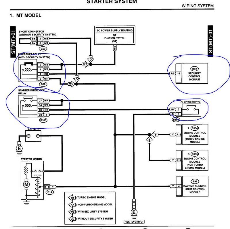
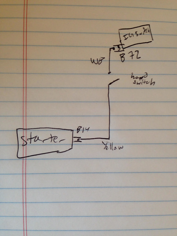
    Okay, electrical question! I'm trying to remove some of the complexity on the car's wiring. Here's a big one I found that I'm convinced I can do without:


    The original starter circuit involves a relay to disallow starting the car if it's not happy about security (that definitely is getting bypassed), a switch for the clutch to be down (that's a pain in the *** as getting in/out of this car isn't as easy as a normal car), and a relay that locks out starting if the clutch switch isn't down.


    Here's the new circuit I propose for this:


    What's everyone think?
    Last edited by Pearldrummer7; 01-18-2015 at 09:26 AM.

  34. #194
    Senior Member billjr212's Avatar
    Join Date
    Feb 2011
    Location
    Frankfort, IL
    Posts
    734
    Post Thanks / Like
    If you go that route, i would make the "hand switch" a momentary switch. That way you have to consciously push it prior to starting the car. Prevent an oops moment by trying to start the car with it in gear. Doubles as a security feature, I suppose, as well. Would have to be by your left hand though, since your right would be busy turning the key.

  35. #195
    Senior Member
    Join Date
    Jan 2014
    Posts
    617
    Post Thanks / Like
    Why take the clutch switch out? If you are concerned about starting the car while working on it, just get a $20 remote switch.

    I wired in a relay in my fusebox to run the starter so I wouldn't have to run the starter solenoid wire the length of the car.


  36. #196
    Senior Member
    Join Date
    Oct 2012
    Posts
    556
    Post Thanks / Like
    I jumpered my clutch switch temporarily. This way I don't have to climb in the car any time I want to start it. When the car is fully driveable and registered I will re-connect the switch.

  37. #197
    Senior Member Pearldrummer7's Avatar
    Join Date
    Feb 2014
    Location
    Asheville, NC
    Posts
    1,230
    Post Thanks / Like
    Quote Originally Posted by tmoretta View Post
    I jumpered my clutch switch temporarily. This way I don't have to climb in the car any time I want to start it. When the car is fully driveable and registered I will re-connect the switch.
    Quote Originally Posted by Jaime View Post
    Why take the clutch switch out? If you are concerned about starting the car while working on it, just get a $20 remote switch.

    I wired in a relay in my fusebox to run the starter so I wouldn't have to run the starter solenoid wire the length of the car.

    The main reason was to eliminate the relay (as that was my last relay in the block, I could eliminate the entire block), but I obviously could just have it interrupt the start wire. The remote switch is a nice idea though.

    Quote Originally Posted by billjr212 View Post
    If you go that route, i would make the "hand switch" a momentary switch. That way you have to consciously push it prior to starting the car. Prevent an oops moment by trying to start the car with it in gear. Doubles as a security feature, I suppose, as well. Would have to be by your left hand though, since your right would be busy turning the key.
    Yup, should've mentioned it'd be a push button or something. And security by obscurity, right?

  38. #198
    Senior Member EODTech87's Avatar
    Join Date
    Feb 2013
    Location
    Copperas Cove, Texas
    Posts
    207
    Post Thanks / Like
    You can just take a hacksaw to that set of relays so that the starter interlock relay is by itself
    -Jason

  39. #199
    Tazio Nuvolari wannabe Scargo's Avatar
    Join Date
    Nov 2013
    Location
    south-central CT
    Posts
    1,611
    Post Thanks / Like
    This might help the above discussion of catch-cans. Might also leave you even more perplexed. It's the latest from a long-running discussion on IWSTI called "The Official STi engine Venting, A/O Separators, and Catch Cans Thread!!"

  40. #200
    Senior Member Pearldrummer7's Avatar
    Join Date
    Feb 2014
    Location
    Asheville, NC
    Posts
    1,230
    Post Thanks / Like
    Quote Originally Posted by EODTech87 View Post
    You can just take a hacksaw to that set of relays so that the starter interlock relay is by itself
    Doing just that. Excellent call.

    Quote Originally Posted by Scargo View Post
    This might help the above discussion of catch-cans. Might also leave you even more perplexed. It's the latest from a long-running discussion on IWSTI called "The Official STi engine Venting, A/O Separators, and Catch Cans Thread!!"
    That helped, then made me more confused, now it makes sense again. A lot to think about with catch cans! Thanks for this.


    After some discussion with many people about trying to get the wheels I want (RPF1), I finally found someone who can help with the rears, and someone else who can help with the fronts -_- much better than nothing, though!

    I'm going to buy 17x8 +45mm fronts (or should I do the 35mm ones they offer?) and the 18x9.5 +38 rears. Tough to find that combo in 5x100 flair, and it'll be a little costly, but they're so light! (15.6 and 18.6 lbs!) Anyone see an issue with my sizing?

Page 5 of 26 FirstFirst ... 3456715 ... LastLast

Tags for this Thread

Posting Permissions

  • You may not post new threads
  • You may not post replies
  • You may not post attachments
  • You may not edit your posts
  •  

Stewart Transport

Visit our community sponsor