-
02-21-2016, 01:25 PM
#201
Senior Member


Originally Posted by
Paul_M

Edward, really looks great, congrats. I should be receiving my panels back next week. All the panels fit really well for me except for one, Drivers top footbox inside panel. (one with hole cut out in your photo above) Front and side lined up well, but I couldn't get it flush with the firewall. Spoke to Dan at FF and he said most guys pull the firewall into the panel. I'm using the thicker FFmetal firewall, for me this was about 1/2" away from the 3/4" frame that runs long the side of engine bay. Wondering if anyone else had a similar experience? Something else I came across was it seems that FF started shipping a different radiator in summer of 2015. I'm #9 of the 20th kits, received my kit in Aug 2015 and my radiator came with angled inlet and outlet. Edward yours looks like it has straight outlet from the photos above. I ordered my breeze radiator shroud a while ago. When I received it, it didn't line up 100%, thought it was just the panel so I used some persuasion to get it to fit, wasn't 100% as I had to pull the top and bottom out a bit, but it worked. I see now that Breeze has a new radiator shroud 32204 for the radiator I was shipped, this one has the fan hole already cut. Mine is already at the PC'er but I'm going to get this new one as I assume it fits better.
Thanks! The DS footbox top inside panel in my build and pics isn't the stock FF part. It's one of the new pieces as designed by 2bking to provide additional space for the Coyote. As such, it's narrower and has a different outside edge profile to match the new inside footbox wall. But it's the same exact length as the one provided by FF -- 15-3/8 inches long -- I just checked. That dimension fits perfectly between the footbox front and firewall. A little snug actually. I too have an .090 thick firewall, although it's not the FFMetals one. The 2bking mod requires a smaller cutout in the firewall, so I made this new one using his layout. But it fits on the 2x2 inch dash tube and between the 3/4 inch tubes just like the stock one. I'm not exactly understanding the problem you're describing. Because of the way the firewall is mounted to the 2x2 inch tube and then the little 3/4 inch vertical piece near the steering column, if the length of the cover doesn't fill properly I don't see how it could be "pulled in" as recommended. Is that the 1/2 inch gap your describing? If so, no way. If you're saying the notch in the top of the firewall is 1/2 inch off, that shouldn't be a problem. That area is all enclosed in the footbox. Or if you're saying your firewall doesn't reach the vertical 3/4 inch tube, that's probably also not a problem since it does attach to the top cover at the end. I snapped a quick pic of that area in my build, with the two top pieces now removed. This is looking forward. Help at all?
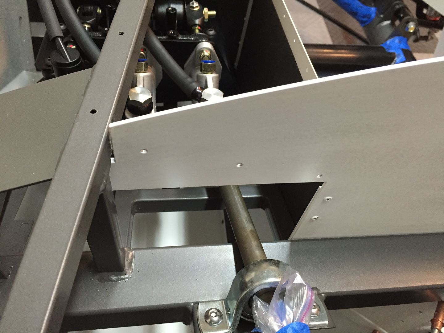
I've heard about and seen pictures of the newer radiator from FF. My kit was also delivered (picked up) in August. I guess I may have just missed. I received an Afco Racing radiator, just like I've used before. The angled tube on the lower hose is a good idea. Routing that hose around the front of the chassis tube and tow hook/tie down can be challenging. I don't think the new radiator is from Afco Racing though. Just like the new manual steering rack was no longer from Unisteer. The gas tank, sender, and pickup also appear to be from a different supplier than in the past. FF is clearly using some different sources.
Last edited by edwardb; 02-21-2016 at 01:41 PM.
Build 1: Mk3 Roadster #5125. Sold 11/08/2014.
Build 2: Mk4 Roadster #7750. Sold 04/10/2017.
Build Thread
Build 3: Mk4 Roadster 20th Anniversary #8674. Sold 09/07/2020.
Build Thread and
Video.
Build 4: Gen 3 Type 65 Coupe #59. Gen 3 Coyote. Legal 03/04/2020.
Build Thread and
Video
Build 5: 35 Hot Rod Truck #138. LS3 and 4L65E auto. Rcvd 01/05/2021. Legal 04/20/2023.
Build Thread. Sold 11/9/2023.
-
02-21-2016, 04:00 PM
#202
Senior Member

IMG_3838-3.JPGIMG_3836.JPG
Thanks Edward, yep my radiator doesn't have any mounting holes cut out either. Really not sure where it's from, not really that polished or finished so not sure what I'm going to do there.
The firewall fits perfectly, I had to trim the notch a little to clear the weld on the 3/4" tube, my issue is I have a gap between that top panel and the firewall if I connect the firewall flush to the 3/4 tube in top corner. Included a couple of photos.
If I don't rivet the firewall in the top corner I can pull it out to close the gap to the top footbox inside panel which I think I will do. I'll then put a spacer so I can fasten it in the top corner, which I think should be fine. Was just wondering if others had the same issue.
Your build is really looking sweet, I see for the floors you went right into the large tube members and not in the flat seat pan, nice idea as you won't see the rivets from below. I unfortunately did 2 lines on the edges of the floor pans, I think I'll add some 3/16 rivets into the tube as you did. I just asked my powder coater to try and do some rivet backs as well so it blends in, he said he could also get me some touch up paint to match the frame color so I could touch up the rivets or any scratches if I need to.
I'm still debating the what insulation to use, I see you've used Lizard skin twice and from looking at your photos has come out really nice.
-
02-21-2016, 05:12 PM
#203
Senior Member

Yea I put rivets for the floor into the 4 inch tubes. Some guys don't, but I prefer to. 1/8 inch rivets are fine IMO. You're right, I didn't put any in the floor pan. All around it in the rest of the frame. Then with lots of adhesive on the pan, I set a cinder block in that area after all the rivets are in. Let it sit for a day or so while it cures, and it's not going anywhere. There will be seat bolts plus the front harness bolt also between the floor and pan.
Your firewall fit is strange. First I've seen that. What you described with a spacer should be fine. Having seen their chassis welding jigs, it's just hard for me to understand that kind of variation. Assuming something is welded wrong. I don't think it's the aluminum piece.
I like Lizard Skin a lot. I'll do the cockpit and the trunk. It does the heat and sound thing well, plus seals everything up. It's pretty tough, so maybe even adds a little strength to the joints. Cost is comparable to other options. I would say the time to apply is probably about the same as well. Like most spray jobs, hours to mask, minutes to spray. But it is a bit messy. Last time I kind of got it everywhere. I'm going to do a better job with drop clothes and barriers this time.
Last edited by edwardb; 02-21-2016 at 05:22 PM.
Build 1: Mk3 Roadster #5125. Sold 11/08/2014.
Build 2: Mk4 Roadster #7750. Sold 04/10/2017.
Build Thread
Build 3: Mk4 Roadster 20th Anniversary #8674. Sold 09/07/2020.
Build Thread and
Video.
Build 4: Gen 3 Type 65 Coupe #59. Gen 3 Coyote. Legal 03/04/2020.
Build Thread and
Video
Build 5: 35 Hot Rod Truck #138. LS3 and 4L65E auto. Rcvd 01/05/2021. Legal 04/20/2023.
Build Thread. Sold 11/9/2023.
-
02-22-2016, 07:07 PM
#204

Originally Posted by
Paul_M

All the panels fit really well for me except for one, Drivers top footbox inside panel. (one with hole cut out in your photo above) Front and side lined up well, but I couldn't get it flush with the firewall. Spoke to Dan at FF and he said most guys pull the firewall into the panel.
When I made the Coyote panels, the original foot box top had the 1/2 gap that Paul_M is seeing and the firewall needed to be pulled forward to close the gap. I corrected the mistake so the top panel fits without the gap. I was never sure if my frame was different or the foot box top had an error and cautioned everyone that used the design that the panels were made to fit my frame and there may be differences in fit for other frames.
-
02-22-2016, 08:19 PM
#205
Senior Member


Originally Posted by
2bking

When I made the Coyote panels, the original foot box top had the 1/2 gap that Paul_M is seeing and the firewall needed to be pulled forward to close the gap. I corrected the mistake so the top panel fits without the gap. I was never sure if my frame was different or the foot box top had an error and cautioned everyone that used the design that the panels were made to fit my frame and there may be differences in fit for other frames.
Interesting. The part you designed fit my chassis perfectly, as the pictures show. So thanks for that! Based on Paul_M's question, I did quickly measure the FF supplied part, and it seemed the same length as the custom part so just assumed it would fit the same. Never tried actually fitting it or checking the angle. I did use the FF supplied part on my first Mk4 build, and it fit OK. Certainly not 1/2 inch off. But it was a much earlier Mk4, and didn't have the access panel. So seems something changed at some point.
Build 1: Mk3 Roadster #5125. Sold 11/08/2014.
Build 2: Mk4 Roadster #7750. Sold 04/10/2017.
Build Thread
Build 3: Mk4 Roadster 20th Anniversary #8674. Sold 09/07/2020.
Build Thread and
Video.
Build 4: Gen 3 Type 65 Coupe #59. Gen 3 Coyote. Legal 03/04/2020.
Build Thread and
Video
Build 5: 35 Hot Rod Truck #138. LS3 and 4L65E auto. Rcvd 01/05/2021. Legal 04/20/2023.
Build Thread. Sold 11/9/2023.
-
02-23-2016, 04:38 PM
#206
Member

Thanks for the detailed write-up on the panel install. Just out of curiosity, did you do anything with the splash guard and the door jam panels or do you fit and powder coat them later when the body is installed?
Doug
Mk4 Roadster #8567, IRS, Levy Racing 427w Stroker, 8-stack EFI
-
02-23-2016, 06:39 PM
#207
Senior Member


Originally Posted by
dougski

Thanks for the detailed write-up on the panel install. Just out of curiosity, did you do anything with the splash guard and the door jam panels or do you fit and powder coat them later when the body is installed? Doug
You're welcome. The door jam panels -- and by that I assume you mean the pieces that go along the top of the door sill and match the curve of the body door opening -- are completely buried on both sides when the build is done. So I don't powder coat those. The splash guards I don't powder coat until after they're fitted, and can't do that without the body installed. I haven't had any yet that didn't require some tweaking. For the Anniversary edition, FF included the front splash guards in the group of white powder coated parts. So in my case those are already done. I'll just have to be careful with the powder coating if they require much modification. Also for the splash guards, I add a coat of bedliner on the side facing the tires. The same material as used on the underside of the body.
Build 1: Mk3 Roadster #5125. Sold 11/08/2014.
Build 2: Mk4 Roadster #7750. Sold 04/10/2017.
Build Thread
Build 3: Mk4 Roadster 20th Anniversary #8674. Sold 09/07/2020.
Build Thread and
Video.
Build 4: Gen 3 Type 65 Coupe #59. Gen 3 Coyote. Legal 03/04/2020.
Build Thread and
Video
Build 5: 35 Hot Rod Truck #138. LS3 and 4L65E auto. Rcvd 01/05/2021. Legal 04/20/2023.
Build Thread. Sold 11/9/2023.
-
02-26-2016, 11:08 PM
#208
Senior Member

Fuel Lines Installed
Today I completed the fuel line installation. It’s basically done with just a few fittings to tighten when the tank goes in the last time and the engine is installed. First let me make one thing clear. I didn’t use any of the FF supplied fuel lines or fittings. That’s a personal choice. The kit supplied lines and fittings, plus the additional ones called out for the Coyote installation, work fine and could certainly have been used. Plain and simple I wanted rigid stainless steel (SS) like my last build for the fuel and brake lines. That takes you down a specific path for fittings to make it all work, and before you know it, none of the FF supplied parts are used. Again, my choice.
There has been lots of discussion and recommendations for the Coyote fuel system, including pump size, supply and return line sizes, etc. The FF Coyote instructions say to use a 255 LPH pump. The Ford Racing instructions say 155 LPH. Guys have used both. I went ahead with the 255 LPH in tank pump from Breeze, which Mark provides with enlarged outlet and inlet tubes for 06AN fittings using his adapters. I decided to use 3/8 inch tubing for both the supply and return lines. 5/16 inch supply and 1/4 inch return line is included with the kit, and data shows this will supply plenty of fuel for the Coyote. But some regulators, including Aeromotive like mine, recommend 3/8 inch for supply and return. There has been a lot of chatter about fuel pump life, pressure from too small fuel lines, etc. Since I was going to use SS, it wasn’t a hard decision to go ahead and just use the 3/8 for both. No downside once bought and installed. Easy now. Real hard later. Decision done.
The SS tubing is from Inline Tube, a source many have used. I’m lucky because they’re local for me. So I’m able to pick up the 3/8 inch fuel and 3/16 inch brake line material in person and specify the tubes are left straight. No shipping, no coils, no straightening. Nice. I used a 10-12 inch length piece of Aeroquip PTFE Racing Hose on each end of both lines, and there will be another about 20 inches long from the regulator to the Coyote. I used Aeroquip FBM1103 PTFE 06AN fittings for all. I have the ability to put flares on the 3/8 inch tubing with my Eastwood flaring tool. But even with a flare and a tube nut, it still takes an adapter to attach the 06AN fitting. Mark at Breeze sells a very nice 3/8 inch OD Tube to 06AN male compression fitting (his #21608) and those work great. Install onto the end of the bare 3/8 inch SS tube and instant 06AN connection. FYI, they are Ham-Let Stainless Steel 316 Let-Lok compression fittings, considered a very high quality piece and rated for 1000+ pounds. I think they’ll do. I had to look them up because I wanted to be sure about installation. Their instructions say 1 and 1/4 turns, and that’s what I did. They seem rock solid. I've got the same fitting on the fuel tank supply line and the fuel rail inlet on the Coyote. I found a fuel filter that I thought would fit and do what I wanted on Summit. A Trick Flow TFS-23006. It’s a 10 micron filter with a spin-off base and easily handles the required fuel flow.
I found out during my last build that 3/8 inch SS is not particularly easy to bend. I used my little Eastwood combination tubing bender, and it was all I could do to bend the 3/8 inch tubing with its short handles. So I picked up a new Rigid 36097 tubing bender. It’s just for 3/8 inch and nearly double the handle length. Worked very well. Glad I did that. I picked up a 10 foot piece of 3/8 inch copper tubing from Home Depot, and used that to make patterns and when fitted, duplicated in the SS. You only get one chance with SS, and with my limited experience I’m not willing to work without a safety net. Best $8 I spent. I wasn’t sure I could do it, but I was able to make the supply and return lines each in one piece. The challenge wasn’t making them so much as getting them into the chassis when done. But they're in and won't be coming back out. The saving grace was the simple bend and short returns I used going into the engine compartment. OK, enough words. Here are some pics.
This is the Aeromotive regulator mounted at the firewall, and the supply and return lines in the engine compartment. It’s not obvious in this picture, but I had to make a new bracket for the regulator to stand it away from the firewall one inch. The main harness for the Coyote needs to pass behind it.
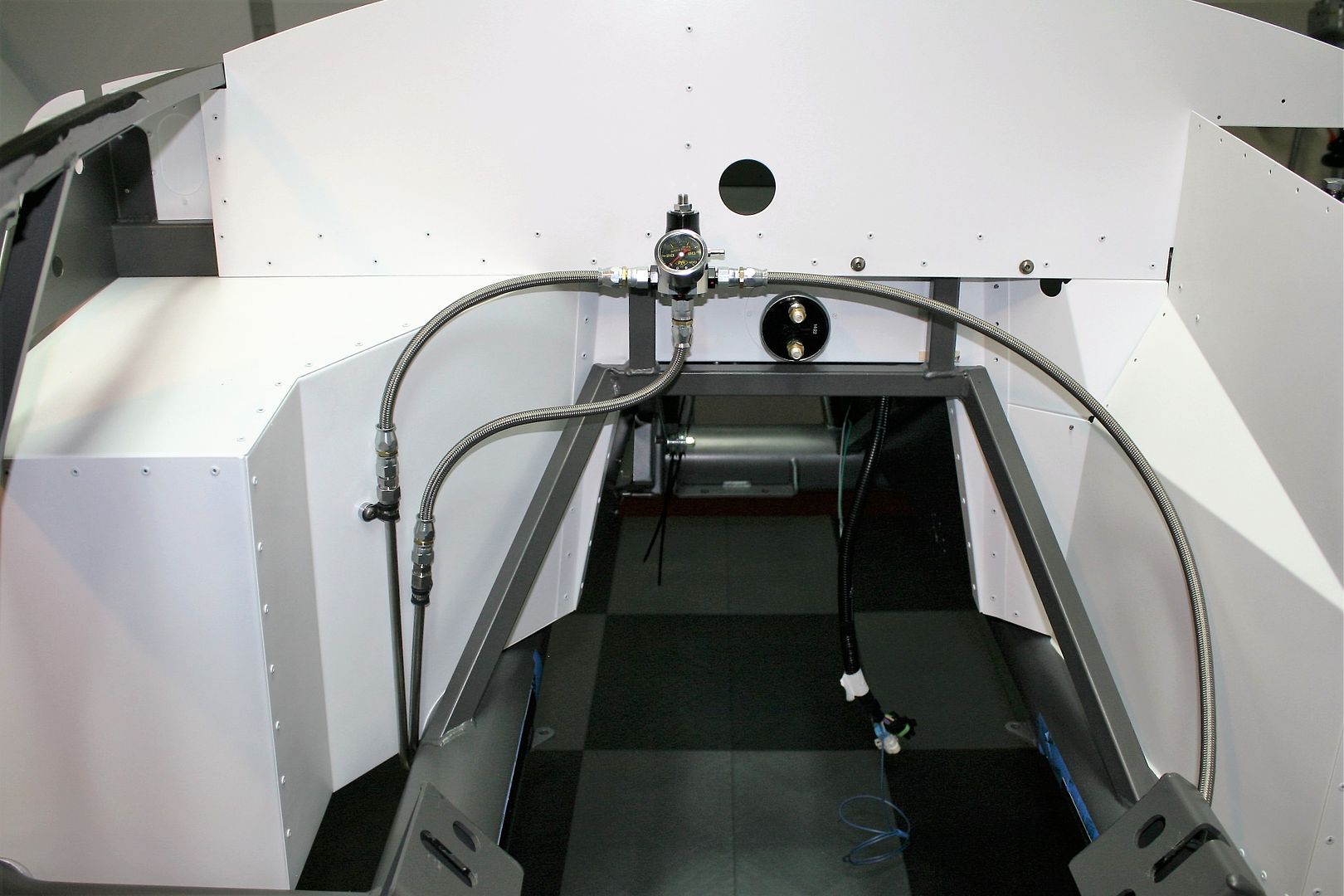
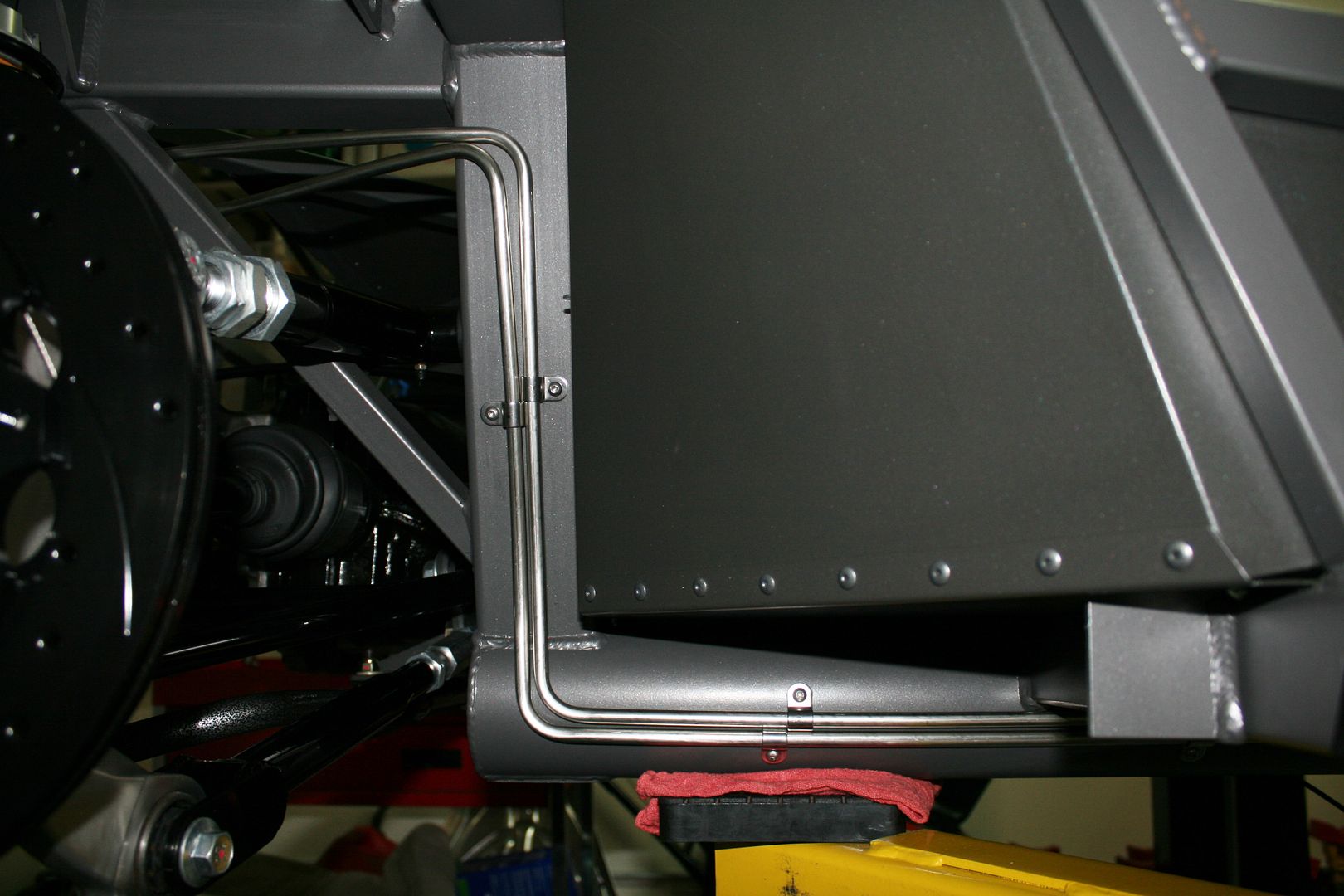
The tubing passes in front of the PS footbox and down the chassis 4 inch tubes. The SS clips are also from Inline Tube. They’re made for a flat surface. But bend the tab and they work fine on the curved tube. All the clips are installed with the provided 10-32 SS button head screws into tapped holes.
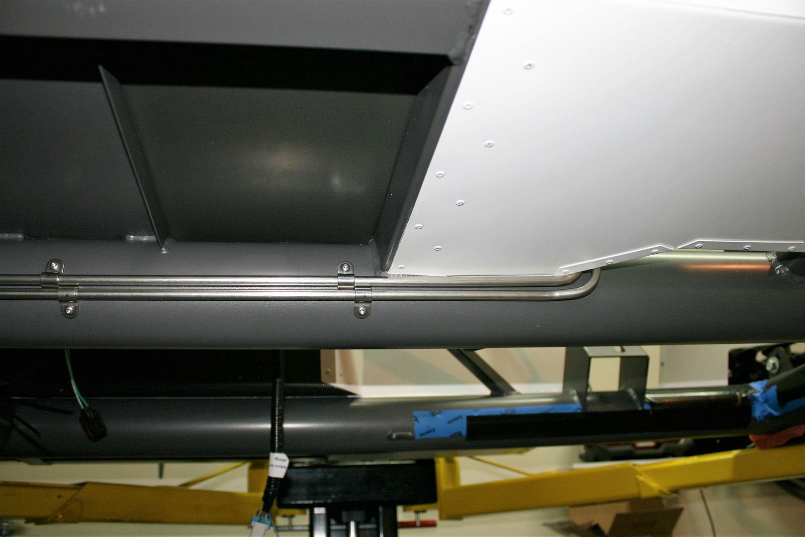
Rest of the way down the 4 inch tube.
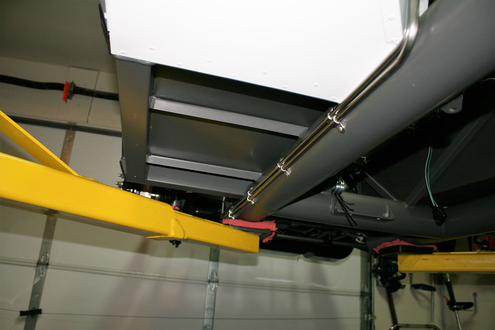
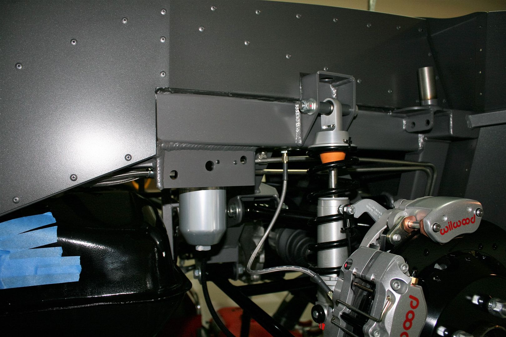
Then up and over the rear suspension. I’m well away from any moving parts. I unhooked the coilover and pushed the rear suspension to the top limit. The UCA is still several inches away from the tubes.
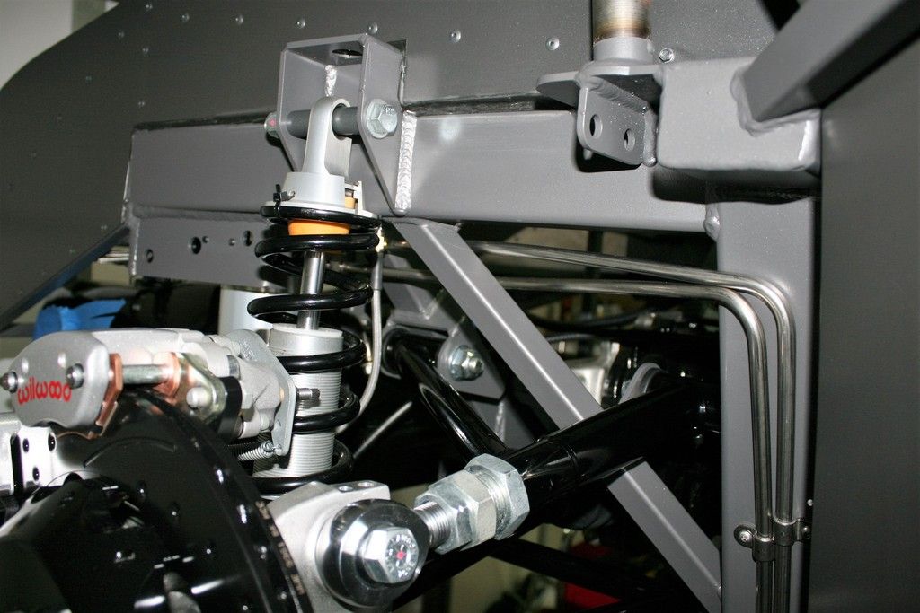
This is the location of the fuel filter. Directly in line with the supply tube and easily accessible from the wheel well to spin off and service the filter. I had to modify the bracket slightly, but that was easy and then mounted here perfectly. You can see the end of the two 1/4"-20 mounting screws tapped into the frame.
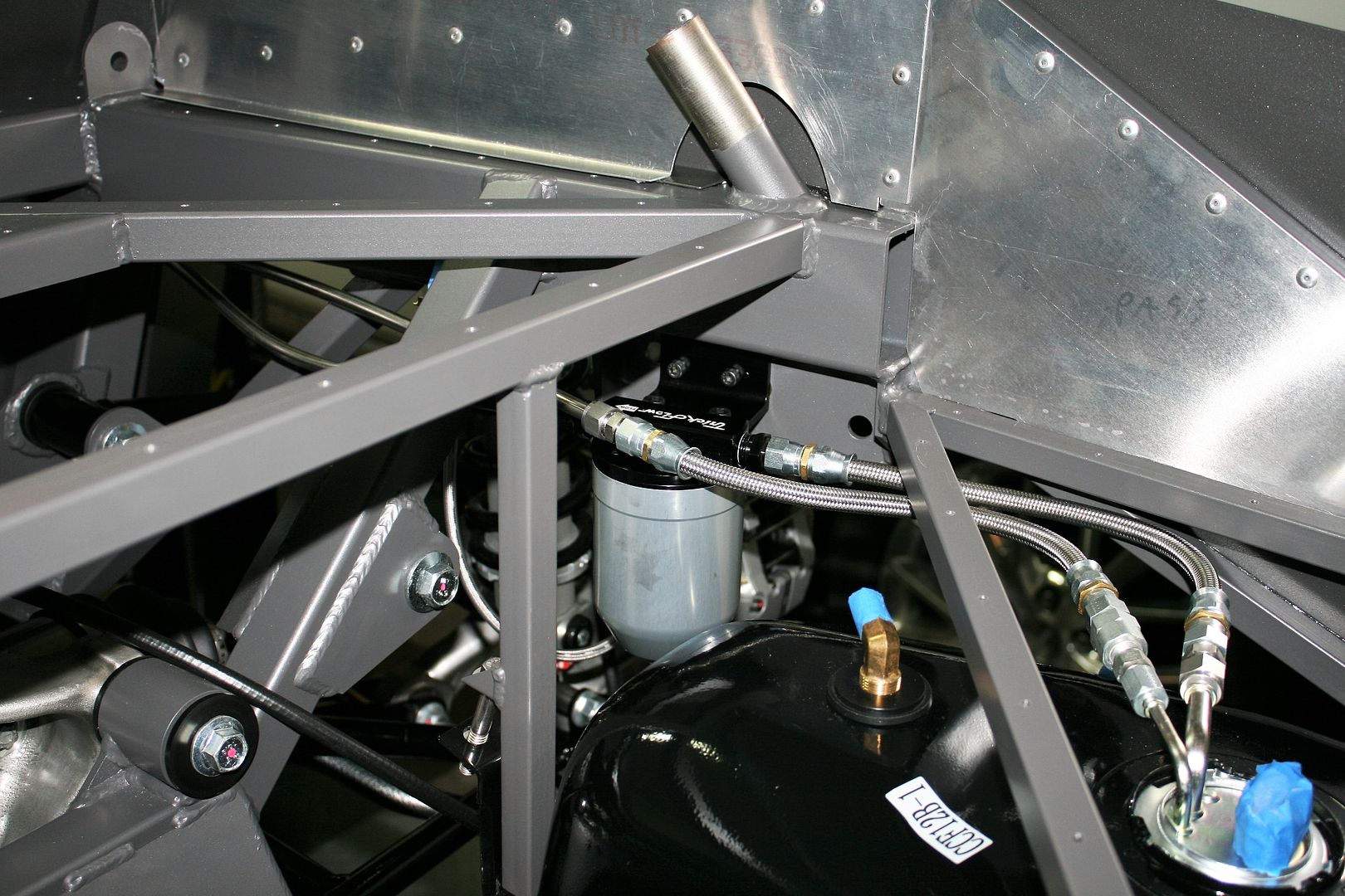
Trunk side view of the lines, filter, and attachment to the fuel tank.
Next is brake lines. More of them, but will be a comparative ease to form compared to the 3/8 inch tubing. I’ve got the routing all planned. Now just need to do it.
Last edited by edwardb; 03-05-2016 at 07:59 AM.
Reason: Corrected Aeroquip part number
Build 1: Mk3 Roadster #5125. Sold 11/08/2014.
Build 2: Mk4 Roadster #7750. Sold 04/10/2017.
Build Thread
Build 3: Mk4 Roadster 20th Anniversary #8674. Sold 09/07/2020.
Build Thread and
Video.
Build 4: Gen 3 Type 65 Coupe #59. Gen 3 Coyote. Legal 03/04/2020.
Build Thread and
Video
Build 5: 35 Hot Rod Truck #138. LS3 and 4L65E auto. Rcvd 01/05/2021. Legal 04/20/2023.
Build Thread. Sold 11/9/2023.
-
02-29-2016, 12:42 PM
#209
Member

Thanks for the fuel line writeup. I have done something similar with the stainless line but have not put together the sections of Aeroquip racing hose. Are there any special tools or techniques to getting this done? Doug
Mk4 Roadster #8567, IRS, Levy Racing 427w Stroker, 8-stack EFI
-
02-29-2016, 02:30 PM
#210
Senior Member


Originally Posted by
dougski

Thanks for the fuel line writeup. I have done something similar with the stainless line but have not put together the sections of Aeroquip racing hose. Are there any special tools or techniques to getting this done? Doug
You're welcome. No, nothing special really. Just to be certain, these are the high pressure style hoses with a Teflon liner and the connectors have a little ferrule (or olive as I guess some call them) that goes over the end of the liner and then is captured between the two connector halves. I find these kind of connectors a bit easier to assemble onto hose than the more traditional AN connectors where you put the end on the hose and then screw the rest of the connector in. These particular Aeroquip connectors happen to be steel, so they're a little more durable to work with and don't mark up with normal tools. A bench vise with some type of protection on the jaws is probably mandatory IMO. I don't have any dedicated AN wrenches or holders. I guess my main feedback is that you have to be real careful and precise with cutting the braid, trimming the liner so it's straight and clean allowing the pieces to go together without too much drama. Use some assembly lube on the final step where you insert the end into the liner. I use the Earl's Performance lube. Good luck!
Last edited by edwardb; 02-29-2016 at 03:45 PM.
Build 1: Mk3 Roadster #5125. Sold 11/08/2014.
Build 2: Mk4 Roadster #7750. Sold 04/10/2017.
Build Thread
Build 3: Mk4 Roadster 20th Anniversary #8674. Sold 09/07/2020.
Build Thread and
Video.
Build 4: Gen 3 Type 65 Coupe #59. Gen 3 Coyote. Legal 03/04/2020.
Build Thread and
Video
Build 5: 35 Hot Rod Truck #138. LS3 and 4L65E auto. Rcvd 01/05/2021. Legal 04/20/2023.
Build Thread. Sold 11/9/2023.
-
02-29-2016, 02:40 PM
#211
Senior Member

I have been using your line routing as reference for mine, you truly set the standard for building. Thank you.
-
03-05-2016, 06:13 AM
#212
Edwardb - thanks for being so clear on all of your parts! Every time I think I have things figured out - you seem to post ideas that are 10 times better. I actually had fuel line fittings in my 'shopping cart' when you posted your fuel line thread. I emptied my cart and went ahead and picked up the Breeze fittings that you listed and they are VERY nice! High quality and about what I was going to spend for lower quality fittings.
I am just now researching the hose fittings and I noticed that Summit shows the FBM1134 as a 45 degree flare - not compatible with the 37 degree Breeze fitting. Am I missing something?
Update: I found this catalog link for the Aeroquip fittings. The FCM and FBM are the same fitting, the C indicates Consumer packaging and the B designates bulk. Based on page 16 of the catalog, the 1103 is the 37 degree version.
http://aeroquipperformance.com/files/2013-catalog.pdf
Last edited by RRussellTx; 03-05-2016 at 07:24 AM.
-
03-05-2016, 08:06 AM
#213
Senior Member


Originally Posted by
RRussellTx

Edwardb - thanks for being so clear on all of your parts! Every time I think I have things figured out - you seem to post ideas that are 10 times better. I actually had fuel line fittings in my 'shopping cart' when you posted your fuel line thread. I emptied my cart and went ahead and picked up the Breeze fittings that you listed and they are VERY nice! High quality and about what I was going to spend for lower quality fittings.
I am just now researching the hose fittings and I noticed that Summit shows the FBM1134 as a 45 degree flare - not compatible with the 37 degree Breeze fitting. Am I missing something?
Update: I found this catalog link for the Aeroquip fittings. The FCM and FBM are the same fitting, the C indicates Consumer packaging and the B designates bulk. Based on page 16 of the catalog, the 1103 is the 37 degree version.
http://aeroquipperformance.com/files/2013-catalog.pdf
Glad my thread was helpful. You'd probably be a little more thankful if I actually posted the right part numbers. 
FBM1103 is the right part number for all the fittings I used. PTFE Racing Hose, Straight, -6 AN Hose to Female -6 AN, SAE 37 Degree Flare. I corrected the post. You found the right part number, and happy that you checked. I looked at the FBM1134 connector because it does have an SAE 45 degree flare (sort of unusual) and thought it might work with the 45 degree double flared ends of the 3/8 inch SS fuel line and a regular tube nut. The flare was the wrong direction though, so back to Summit they went and I used FBM1103's and the Let-Lok compression fittings with no flares for all the connections. I had both part Aeroquip numbers in my activity spreadsheet, and (of course) picked the wrong one when I wrote the post. Sorry for the confusion.
Last edited by edwardb; 03-05-2016 at 08:13 AM.
Build 1: Mk3 Roadster #5125. Sold 11/08/2014.
Build 2: Mk4 Roadster #7750. Sold 04/10/2017.
Build Thread
Build 3: Mk4 Roadster 20th Anniversary #8674. Sold 09/07/2020.
Build Thread and
Video.
Build 4: Gen 3 Type 65 Coupe #59. Gen 3 Coyote. Legal 03/04/2020.
Build Thread and
Video
Build 5: 35 Hot Rod Truck #138. LS3 and 4L65E auto. Rcvd 01/05/2021. Legal 04/20/2023.
Build Thread. Sold 11/9/2023.
-
03-05-2016, 11:14 AM
#214
Senior Member

Brake Lines Completed
This week I completed the stainless steel (SS) brake lines. I did SS lines on my last build, and happy with how they turned out so did them again. As I mentioned in my fuel line update, the SS tubing came from Inline Tube, a local source for me so I was able to pick up the 10 foot sections in straight pieces. I also bought the SS tube nuts and SS flat line clamps from Inline Tube. I have the Eastwood Pro Tube Flaring tool from my last builds. I did my entire last SS build with two bad flares I detected right after I made them. One I didn’t have positioned properly so the fold was all wrong. The second had a tiny crack, so I did another. The rest were perfect the first time every time. This time around, I had quite a challenge getting good flares. Read all the instructions (again), watched lots of videos, did every tip/hint I could find, and still about half had one or more splits. I talked to the guys at Inline Tube. They said no one else had reported any problems but bring my tool and tubing over and they would take a look. They did several flares with my tool in my tubing and (of course) they were perfect. They also did a few more with my tool in material they said was the hardest they have to flare, and they too were perfect. So convinced it was operator error, I did more practicing. Finally, I determined I was using too much force on step 2. Call it adrenalin, too many Wheaties, whatever, I was pushing too hard. I lightened up a bit, and was able to get consistently perfect flares. I don’t know why I didn’t have this same issue the last time around. Clearly I was working a little differently. Proves that practice and having the right touch is pretty important. BTW, steel flares with this tool are not nearly so sensitive. You can mash step 1 and step 2 all the way to the stops and get amazingly perfect flares every single time. I'm also happy to report I did all the brake lines without a single instance of doing the flare before installing the tube nut. That's a record for me. But I'm sure I'm the only one that does that...
I’ll cut to the chase. Once I had everything done and installed, I decided to go ahead a bleed the brakes. First to make sure I really did have good flares and no leaks. And second to make sure the Wilwood stuff all worked properly. As long as it took to get the Wilwood brakes, I didn’t want to take the chance that something needed their attention and I’d be back in the waiting game. I’m happy to report no leaks anywhere, a hard pedal, and brakes seem to be working properly. Whew! Kind of a big milestone in the build.
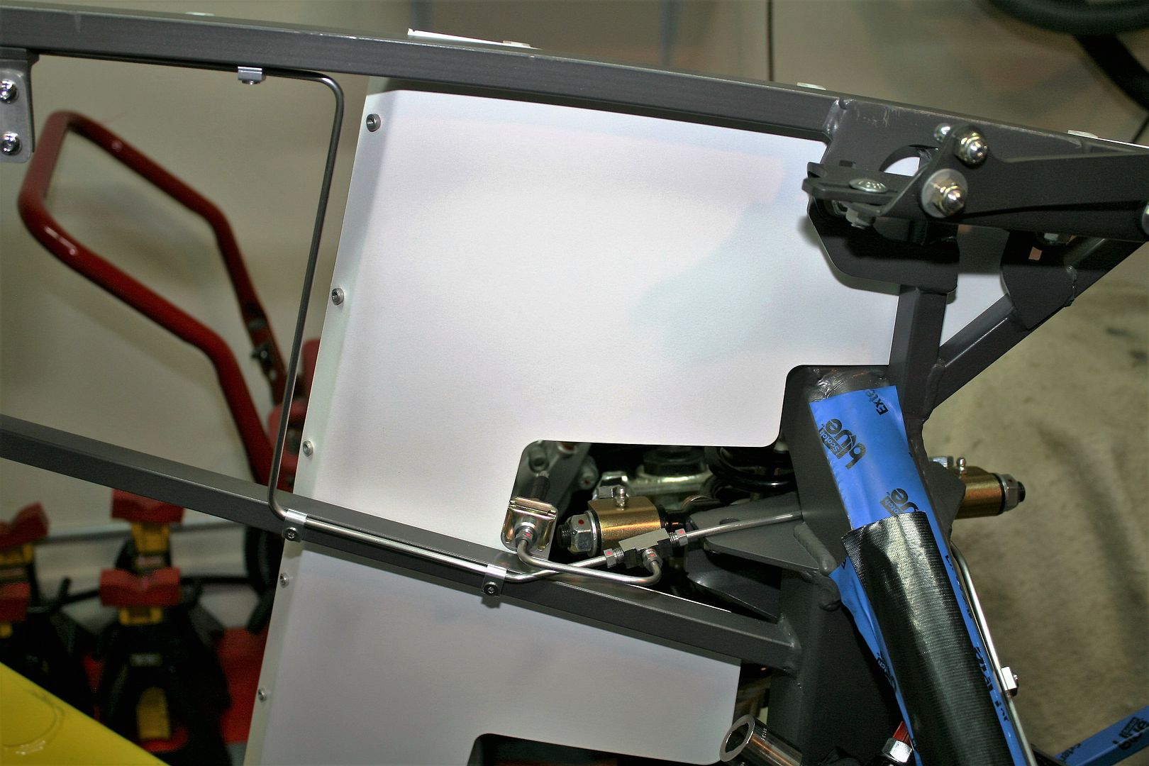
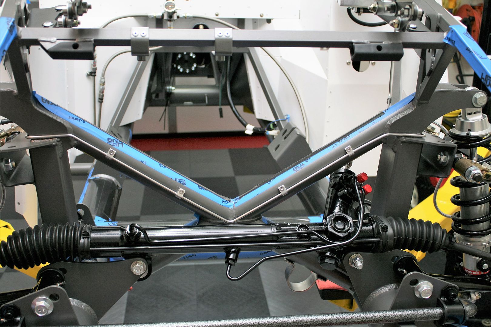
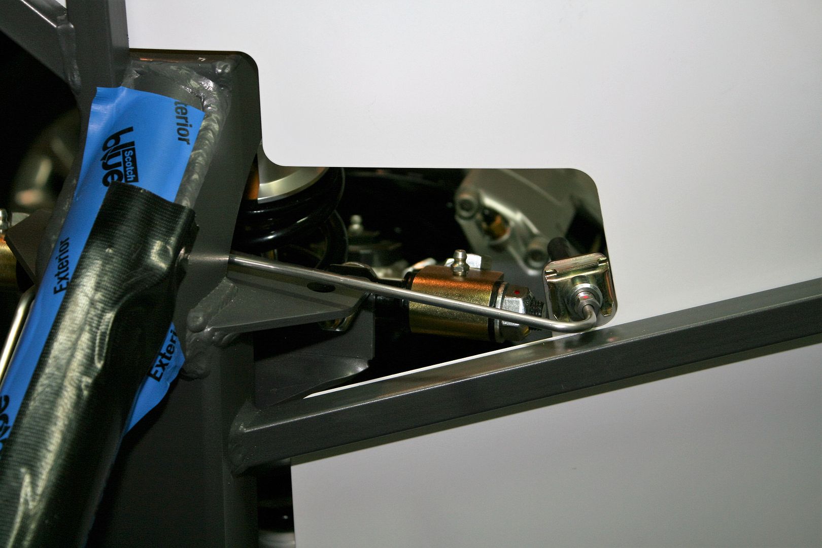
Now for more details of the installation. This is my first time using a Wilwood pedal box with the MC’s inside the footbox. My last build had the Wilwood box, but with a hydroboost unit and regular double MC on the outside. After looking at a lot of routing schemes, I ended up with the rear brake line down the inside corner of the footbox, and the front brake line out of the top outside the 3/4 inch tube. More details in the pics. I used the provided FF steel lines to make patterns of the more complicated pieces, and then duplicated in the SS tubing when satisfied with the fit. I was careful to mark the exact location of the bender on the pattern as I was making it, and then using those marks the SS pieces came out just right. Like the fuel lines, I was able to use a single piece of tubing from the front to the back. So from the rear MC to the rear tee it’s one piece. No unions. Nothing wrong with unions, just fewer parts, flares, and eliminates possible leak sources.
I’m using the CNC reservoirs, so hooked up the supply lines to the three MC’s. I was able to fit the three lines through the unused clutch cable hole. It was in the perfect location plus eliminated having to drill through that thick (and hard) footbox front. This pic also shows where I brought out the front circuit. It’s on the outside, so will be partially hidden with the body on. Also had to get it below where the front harness cable will be attached.
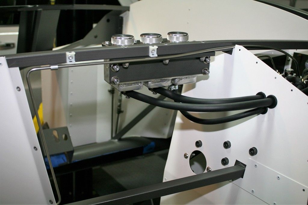
This is how I routed things inside the footbox. All the hydraulics are there except the pressure line for the clutch. It will get routed behind the 2x2 tube down to the clutch after I install the engine/trans.
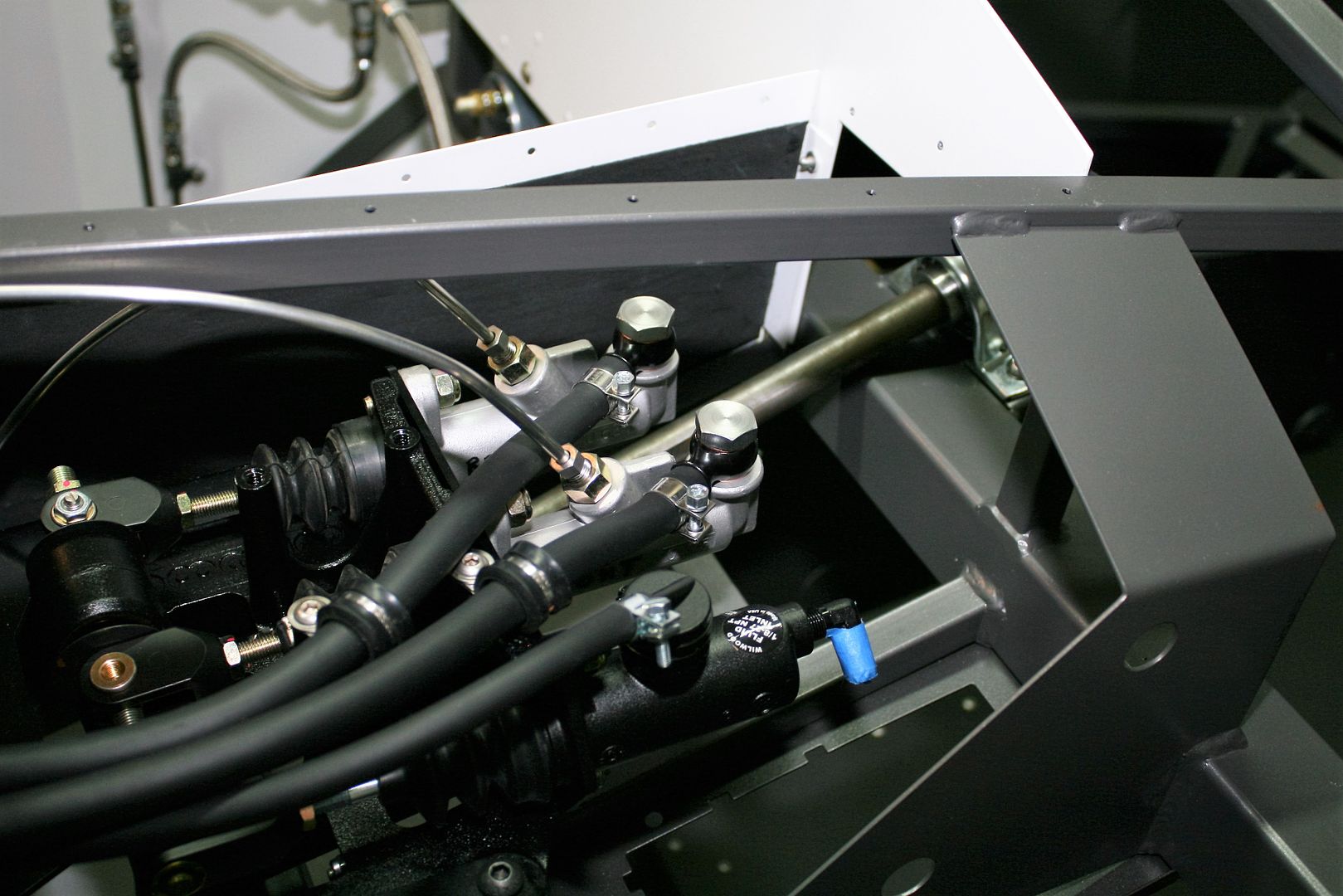
Front DS from the MC, and the tee going to the PS. These line clamps are Allstar ALL18320. Padded clamps are fine. I just think these look a little cleaner. Strictly a personal choice.
Front crossover along the top of the X-frame, again with the Allstar clamps and tapped holes.
PS front. Nothing too exciting here.
Last edited by edwardb; 03-05-2016 at 09:16 PM.
Build 1: Mk3 Roadster #5125. Sold 11/08/2014.
Build 2: Mk4 Roadster #7750. Sold 04/10/2017.
Build Thread
Build 3: Mk4 Roadster 20th Anniversary #8674. Sold 09/07/2020.
Build Thread and
Video.
Build 4: Gen 3 Type 65 Coupe #59. Gen 3 Coyote. Legal 03/04/2020.
Build Thread and
Video
Build 5: 35 Hot Rod Truck #138. LS3 and 4L65E auto. Rcvd 01/05/2021. Legal 04/20/2023.
Build Thread. Sold 11/9/2023.
-
Post Thanks / Like - 0 Thanks, 1 Likes
-
03-05-2016, 11:20 AM
#215
Senior Member

Brake Lines Completed (continued)
For the rear circuit, went down inside the corner of the footbox as already stated. I confirmed the Coyote DBW pedal assembly is far away from the line. I’m not sure a more traditional accelerator pedal, cable, etc. would be the same.
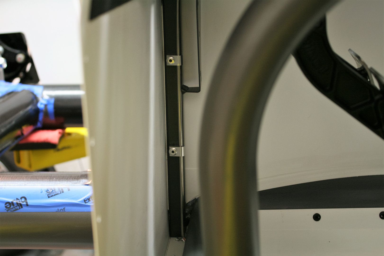
Out through the bottom of the footbox. Still need to put some filler in the hole. It had to be big enough to get the tube nut through since I had to pre-flare the line with the flaring tool in my bench vise. The reflection of the camera flash makes it look there's a flat or kink in that bend. There isn't. It's a smooth bend.
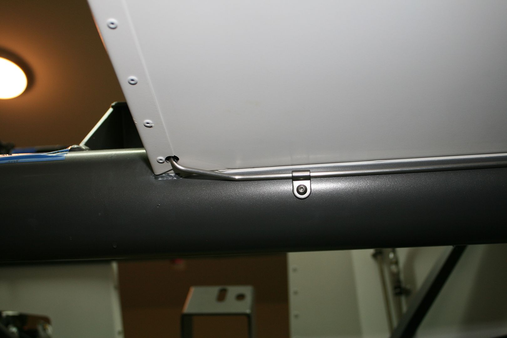
Down the outside of the DS 4 inch chassis tube. These are the Inline Tube line clamps. Same as I used for the fuel line, just a different size. Held with 10-32’s in tapped holes.
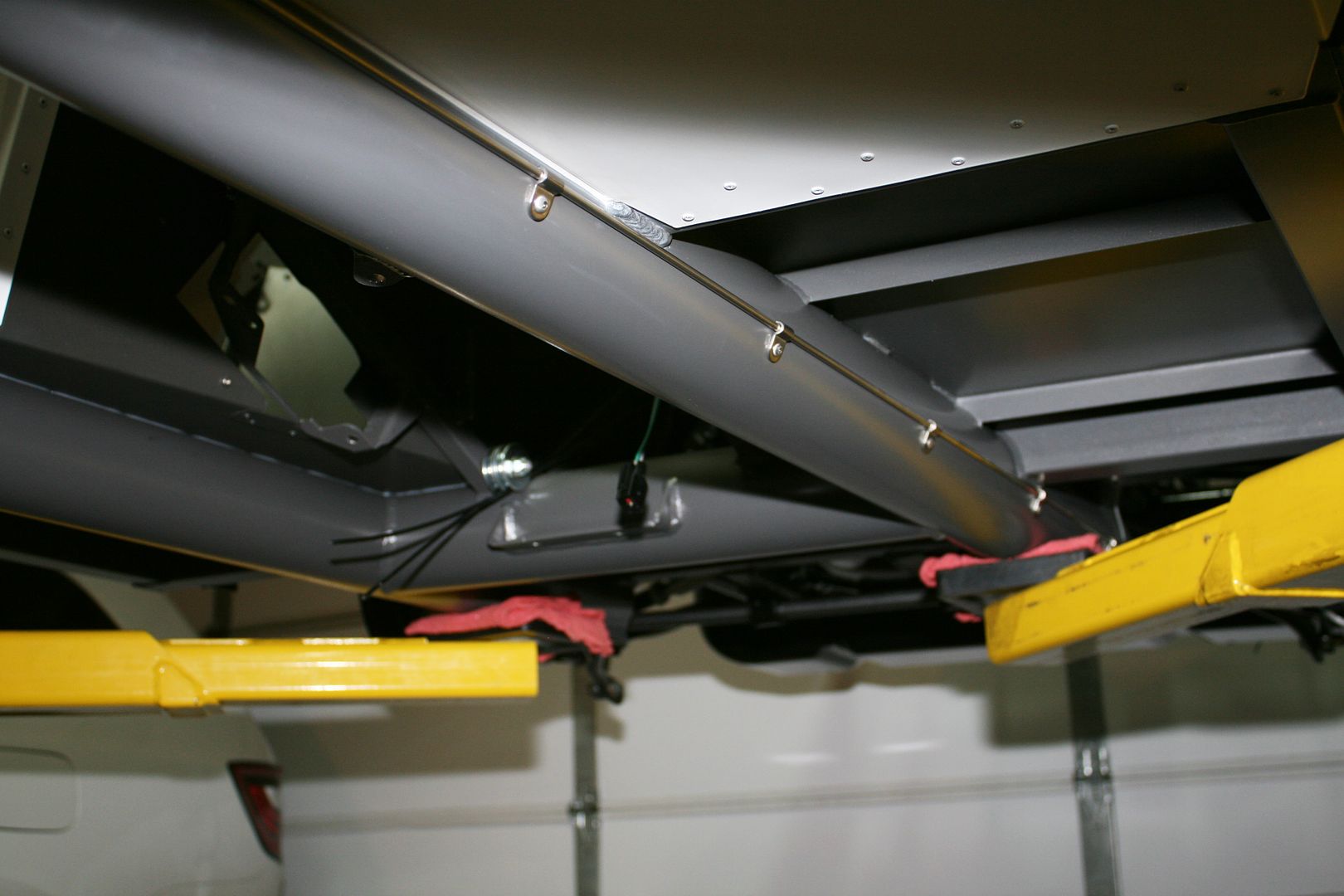
Then up in front of the rear suspension, similar to the fuel lines.
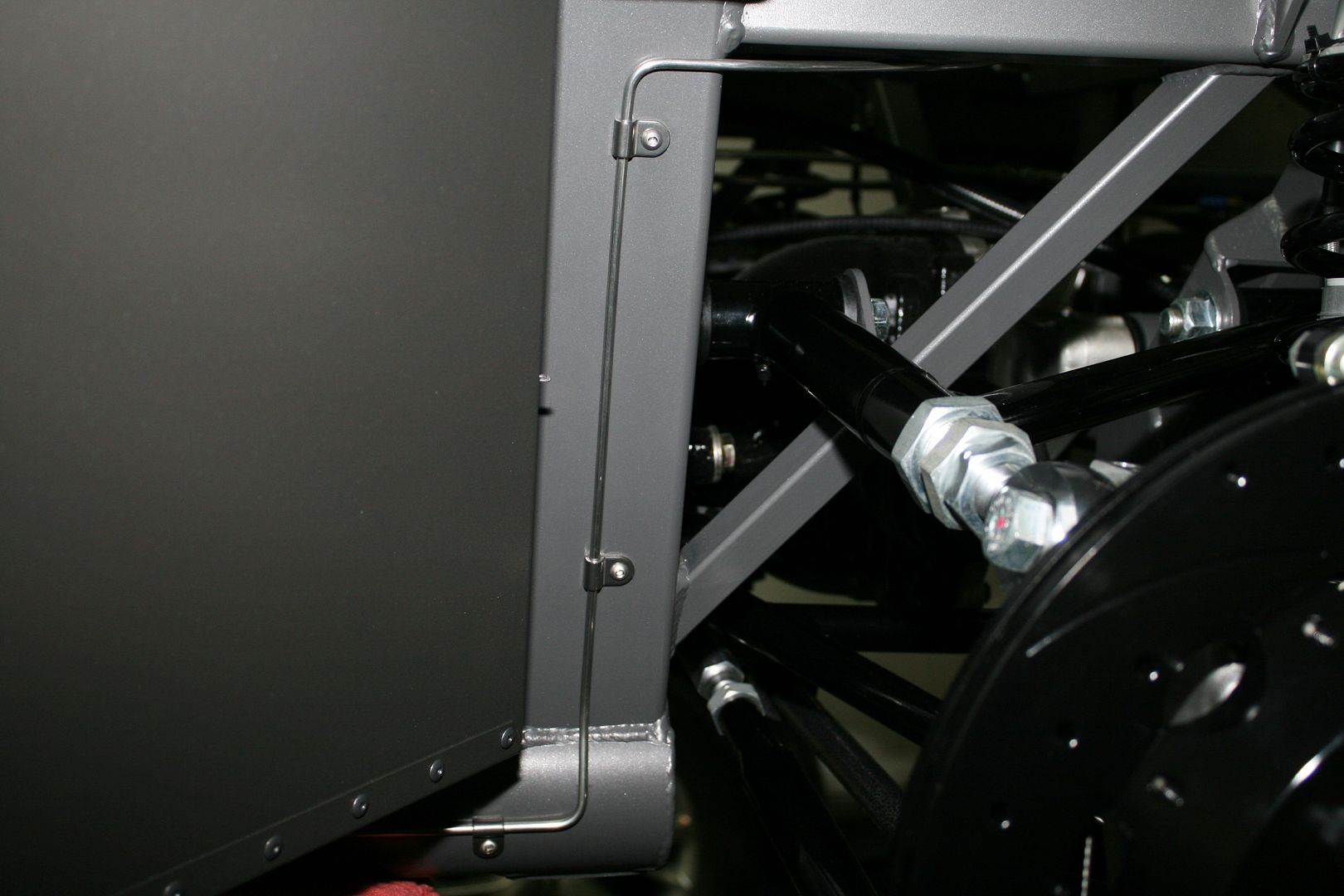
To the rear tee on the DS. Because of the location of the flex line bracket, there isn’t enough height to the trunk floor to put the “T” directly in the fitting as FF shows in their instructions.
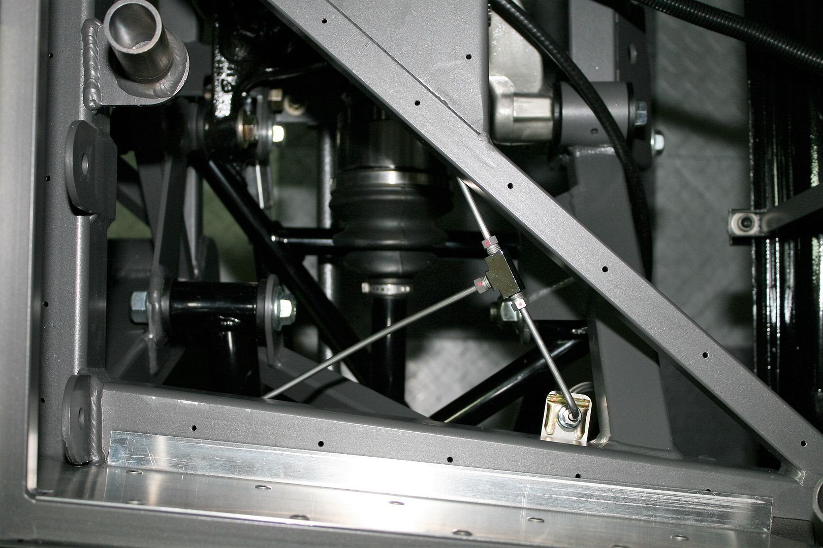
Then over to the rear PS. Again, not too exciting. There is a line clamp directly underneath where this picture is taken. Same location as the other side, also not shown. Couldn’t get decent pictures because of all the suspension parts going on under there. Made it interesting to reach up in there to install them.
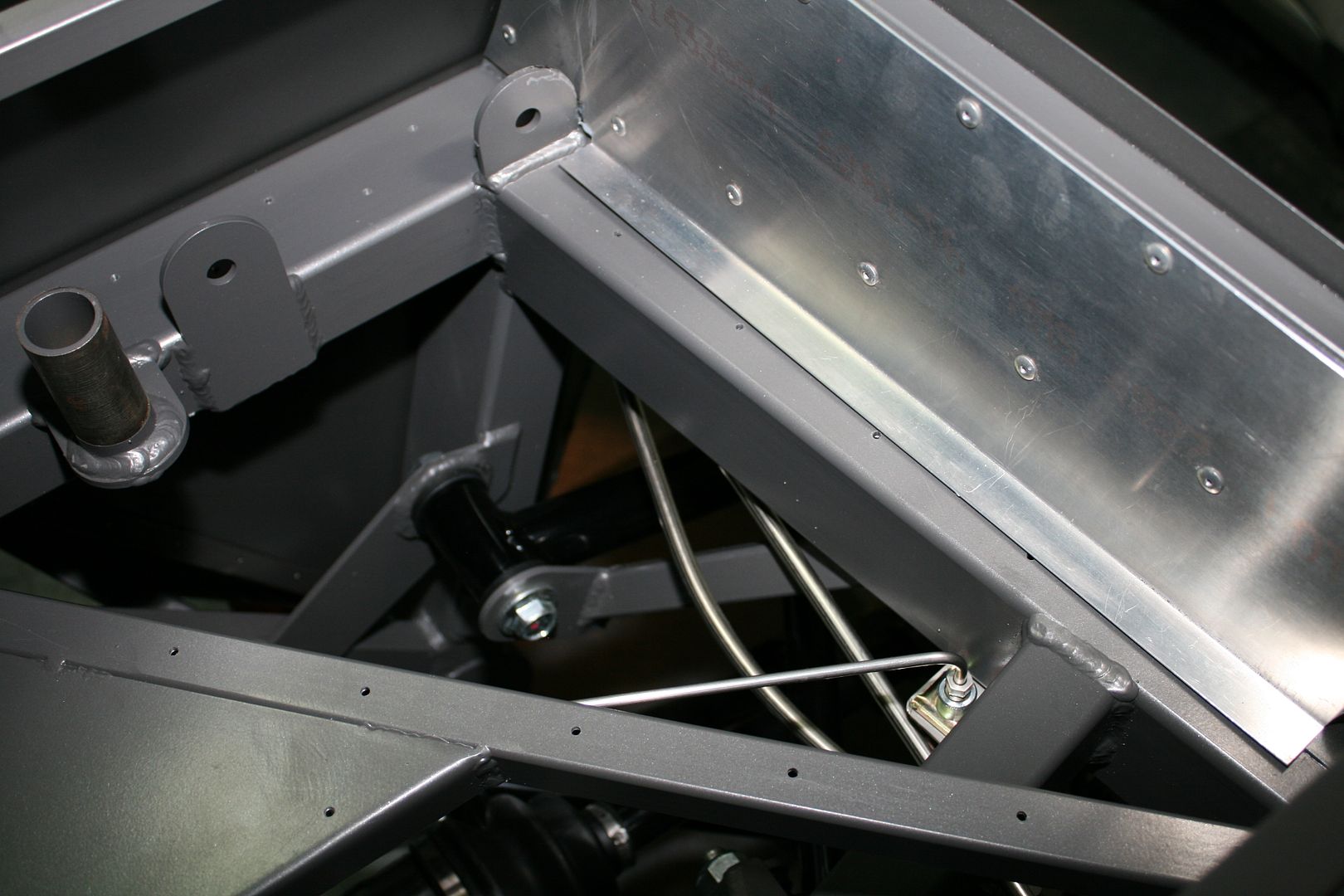
That’s it for the installation. Looks pretty simple when it’s all done. But it’s a bit of work to get there. For the bleeding, I “bench bled” the MC’s on the car, with temporary lines from the MC’s back to the open top of the reservoirs. Just pumped the pedal until all fluid. Then, with the regular lines back on the MC's, I used the CNC pressure cap to pressure bleed at each caliper. With 4-5 pounds of air into the top of the reservoir, just crack the bleeder and wait for the air to come out and only fluid flowing. No pedal pumping. It’s way too easy. Just watch the level in the reservoir. I went around twice just to make sure all the air was out. The Wilwoods are interesting. All the calipers have a top and bottom bleeder. Make sure to use the top one! For the rears, there are bleeders on each caliper. The instructions say to do the outside one first. I used exactly one 32 oz bottle of Valvolene DOT 3&4 synthetic brake fluid. When done, did lots of pumping and no sign of any leaks anywhere. Held the pedal down hard a couple times for one minute plus, and seems to hold fine and again no leaks. Obviously I’ll continue to keep an eye on it, including especially when it’s go-kart and driving time. But looks good now.
Next step is to get serious with electrical. I already have the rear harness in, but need to finalize it. Then going to get the main power wiring in including the Breeze front battery mount. It’s snowing now (no comments please!) but the weather forecast is showing lots of 40-50-60’s starting in the next day or so, the weeks ahead, and into next month. I think we may be turning the corner! Ready to get back out driving with #7750.
Last edited by edwardb; 03-05-2016 at 09:23 PM.
Build 1: Mk3 Roadster #5125. Sold 11/08/2014.
Build 2: Mk4 Roadster #7750. Sold 04/10/2017.
Build Thread
Build 3: Mk4 Roadster 20th Anniversary #8674. Sold 09/07/2020.
Build Thread and
Video.
Build 4: Gen 3 Type 65 Coupe #59. Gen 3 Coyote. Legal 03/04/2020.
Build Thread and
Video
Build 5: 35 Hot Rod Truck #138. LS3 and 4L65E auto. Rcvd 01/05/2021. Legal 04/20/2023.
Build Thread. Sold 11/9/2023.
-
03-05-2016, 12:40 PM
#216
Senior Member

Hey Edward, Amazing progress as always and thanks again for the detailed posts, a big help. Was wondering what hoses / fittings you used to connect from the master cylinder to the remote reservoirs, they don’t look like the ones in the kit or that came with the CNC reservoirs, but look great? Also were the tops of your CNC reservoirs perfectly aligned. The middle one on mine seems a little off? I’m running one 3/8” fuel line for my setup. I as well used a 6AN fuel pick up from Mark. Aeromotive suggests I use 1 inline 40 micron filter between tank and mechanical pump, so I’m thinking of removing the 50 mesh filter on the end of the fuel pickup. My logic is I would rather something get caught in the filter which is easy to replace vs restrict the flow on the fuel pick up, which I then need to remove from tank to clean. Did yours have a similar mesh filter on the end and did you keep it on?
Also for anyone else that has interest I bought a book to read up and learn on fuel / brake line connections as frankly I know very little, (Practical Fabrication and Assembly Techniques by Wayne Scraba - $20 bucks on Amazon) I found it interesting and brought me up to speed on different fittings / adapters etc. It did also mention that SS is difficult to work with, especially when trying to do the 45 degree double flares as can be prone to splitting…. Thanks again for taking the time to post, it’s a great help. Cheers
-
03-05-2016, 01:55 PM
#217
Senior Member


Originally Posted by
Paul_M

Hey Edward, Amazing progress as always and thanks again for the detailed posts, a big help. Was wondering what hoses / fittings you used to connect from the master cylinder to the remote reservoirs, they don’t look like the ones in the kit or that came with the CNC reservoirs, but look great? Also were the tops of your CNC reservoirs perfectly aligned. The middle one on mine seems a little off? I’m running one 3/8” fuel line for my setup. I as well used a 6AN fuel pick up from Mark. Aeromotive suggests I use 1 inline 40 micron filter between tank and mechanical pump, so I’m thinking of removing the 50 mesh filter on the end of the fuel pickup. My logic is I would rather something get caught in the filter which is easy to replace vs restrict the flow on the fuel pick up, which I then need to remove from tank to clean. Did yours have a similar mesh filter on the end and did you keep it on?
Also for anyone else that has interest I bought a book to read up and learn on fuel / brake line connections as frankly I know very little, (Practical Fabrication and Assembly Techniques by Wayne Scraba - $20 bucks on Amazon) I found it interesting and brought me up to speed on different fittings / adapters etc. It did also mention that SS is difficult to work with, especially when trying to do the 45 degree double flares as can be prone to splitting…. Thanks again for taking the time to post, it’s a great help. Cheers
OK, lots of questions. No problem. Let me see... No, the fittings on the CNC reservoirs and the hoses are not what came with the kit or from CNC. I started with the sizes of the hose barbs that came on the two brake MC's and the clutch MC. Then matched that to the 1/8 inch NPT threads in the bottom of the CNC reservoirs. The two brake reservoir fittings are Gardner-Westcott J9032. The clutch reservoir is a Gardner-Westcott J9027. I would have liked it to be a right angle like the other two, but didn't find one in the right combination. The matching 3/8 and 1/4 inch ID hose is brake line reservoir specific hose from a local business here in Michigan that also sells on eBay. I've used it before and seems like good stuff. Also like that it's black. I worry about stuff like that. Probably shouldn't... My CNC reservoirs were aligned OK. There have been some reports of them leaking. But I'm on my third set and no issues. Hope it stays that way.
For the fuel filters -- kind of different situations. Mine is EFI. Sounds like yours is carb'd since you mention a mechanical fuel pump. In both cases a filter is highly recommended for the fuel tank pickup or pump. Often called a sock. It's a rough filter, or maybe better yet called a strainer, intended only to keep any big stuff from being picked up. Typically in the 100 micron range. For a pump pickup like mine, it's usually a flat piece, and yes I have one installed. For a pickup only, the ones I've seen are a little round filter on the end of the tube. You should have one of these kinds of filters in all cases. It's typically a low maintenance item. For the actual fuel line, for a carb setup, you should have a filter between the mechanical fuel pump and the carb inlet. Usually 40 micron is recommended. For an EFI setup, it's recommend the filter is between the pump and the engine, and in the 10 micron range. I posted the picture of the one I'm using mounted next to the fuel tank.
As I said in my write-up, the trouble I had with the SS tubing was unusual for me, and not an issue in my last build. I hesitated to even post about it because guys shy away from SS because it is a bit more difficult to use that plain steel. But with the right material (which I had), the right tool (also which I had), and the right technique (something I was a little short on), it's completely manageable. Clearly though there's a difference between someone that does it all the time, like the guys at Inline Tube that seemed they could make good flares in their sleep, and me who has done it twice with a couple years in between. But based on what I learned, I would use it again no problem. And hopefully without the bit of drama like this time.
Hope that helps!
Last edited by edwardb; 03-05-2016 at 02:07 PM.
Build 1: Mk3 Roadster #5125. Sold 11/08/2014.
Build 2: Mk4 Roadster #7750. Sold 04/10/2017.
Build Thread
Build 3: Mk4 Roadster 20th Anniversary #8674. Sold 09/07/2020.
Build Thread and
Video.
Build 4: Gen 3 Type 65 Coupe #59. Gen 3 Coyote. Legal 03/04/2020.
Build Thread and
Video
Build 5: 35 Hot Rod Truck #138. LS3 and 4L65E auto. Rcvd 01/05/2021. Legal 04/20/2023.
Build Thread. Sold 11/9/2023.
-
03-05-2016, 02:28 PM
#218
Senior Member

Many Thanks Edward, your comments always help! Is the local supplier of the rubber brake hoses "Brake Hoses Unlimited" they look really nice?
-
03-05-2016, 05:54 PM
#219
Senior Member


Originally Posted by
Paul_M

Many Thanks Edward, your comments always help! Is the local supplier of the rubber brake hoses "Brake Hoses Unlimited" they look really nice?
That's the one.
Last edited by edwardb; 03-05-2016 at 08:11 PM.
Build 1: Mk3 Roadster #5125. Sold 11/08/2014.
Build 2: Mk4 Roadster #7750. Sold 04/10/2017.
Build Thread
Build 3: Mk4 Roadster 20th Anniversary #8674. Sold 09/07/2020.
Build Thread and
Video.
Build 4: Gen 3 Type 65 Coupe #59. Gen 3 Coyote. Legal 03/04/2020.
Build Thread and
Video
Build 5: 35 Hot Rod Truck #138. LS3 and 4L65E auto. Rcvd 01/05/2021. Legal 04/20/2023.
Build Thread. Sold 11/9/2023.
-
03-12-2016, 10:52 AM
#220
Senior Member

This Week’s Update
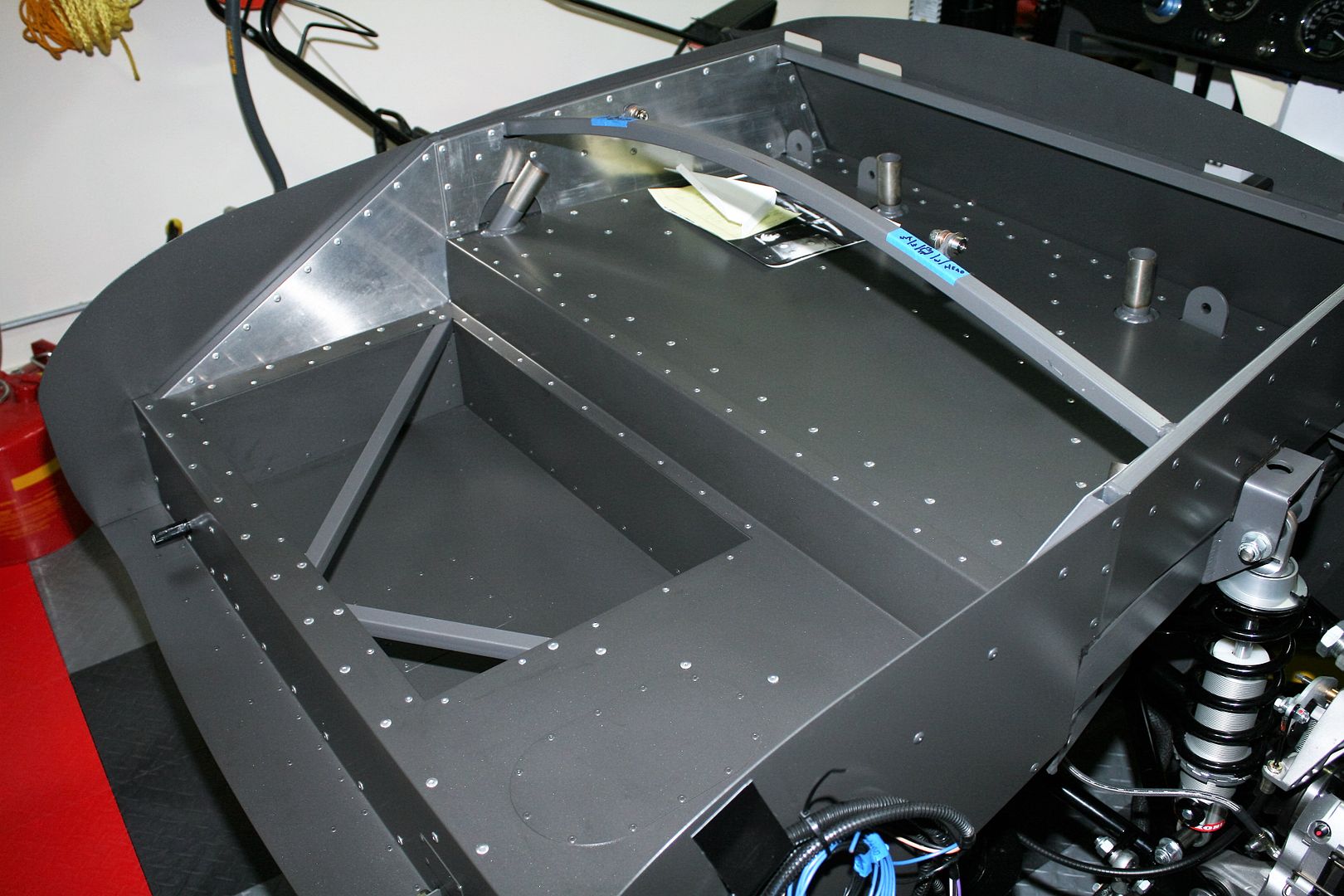
It’s been a busy week with the build plus other stuff, but still made some good progress. Also a setback unfortunately. More about that later. After completing the fuel and brake lines, the next step was to finally install the rear harness. I did the usual routing down the inside DS top corner of the transmission tunnel and to the upper trunk floor. But then took it off to the side a bit around the added 5 inch box in the lower trunk area. Just made the routing a little neater without getting too tight between the tank and the box. Plus there’s enough length to still have enough wire on the DS corner. Before attaching the rear harness with padded clamps and rivets, I did pull two extra wires through it. One for a trunk light, that I’ll add to the courtesy light circuit along with the cockpit footbox lights. The other is off the brake circuit. I have an idea for a center brake light. We’ll see… I also shortened the fuel sender and fuel pump wires to make it a bit neater back there.
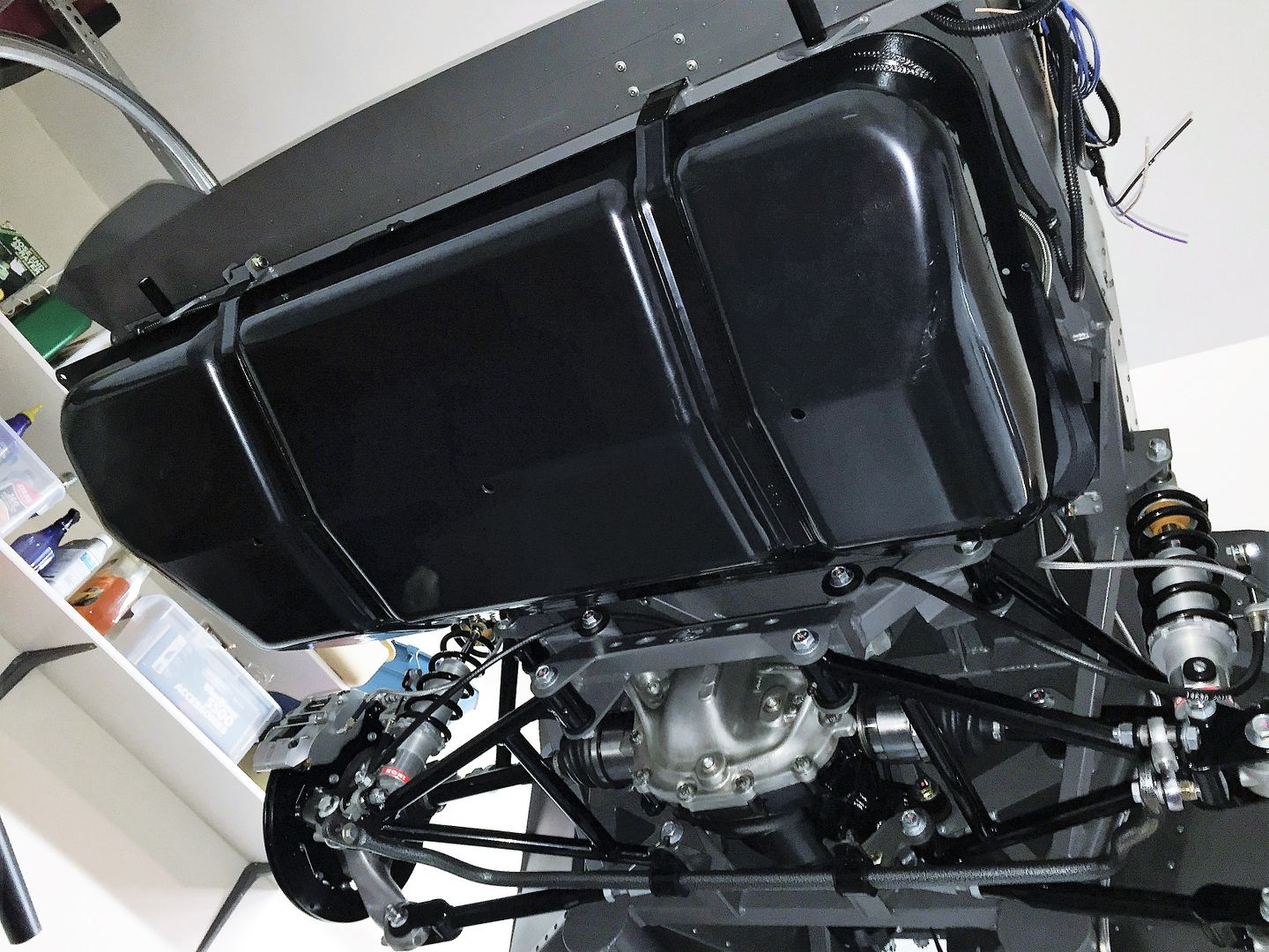
With the rear harness installed, did the final installation on the upper and lower trunk floors, trunk box, and rear cockpit wall. That’s it for panel installation until final assembly with just a few pieces left. Then installed the gas tank for hopefully the last time. I added tie wraps around the sender and pump plugs. I haven’t used an in-tank fuel pump before, and haven’t had any issues with the sender plug. But I’ve heard of several guys having problems with the connectors being loose or intermittent. Not a huge tragedy for the sender, but not good for the fuel pump obviously. I have to agree the locking tab is a bit less than a positive lock. A larger size tie wrap cinched around the connector and holding the tab seems like easy insurance. A short trip to my friends at Ace for a longer bolt on the PS fuel tank strap (common problem…) and I was good to go.
Rear harness and balance of trunk panels installed:
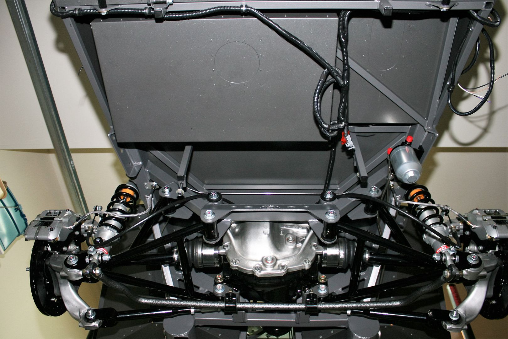
Now with tank installed. At the top of the pic you can see I put the little blocking plate for the PS tank strap on the outside and secured it with screws versus inside, riveted, and buried under the carpet, insulation, etc. Since I chose to not use the trunk floor access panels, being able to drop the tank relatively easily is important. The PS tank strap won’t swing out of the way unless that blocking plate is removed. So tried to make it a bit easier. Hopefully it will stay right where it is for a long time. Never get tired of seeing that rear suspension. It's a beautiful thing.
Top side of completed trunk area. As already mentioned, I'm leaving the braces.
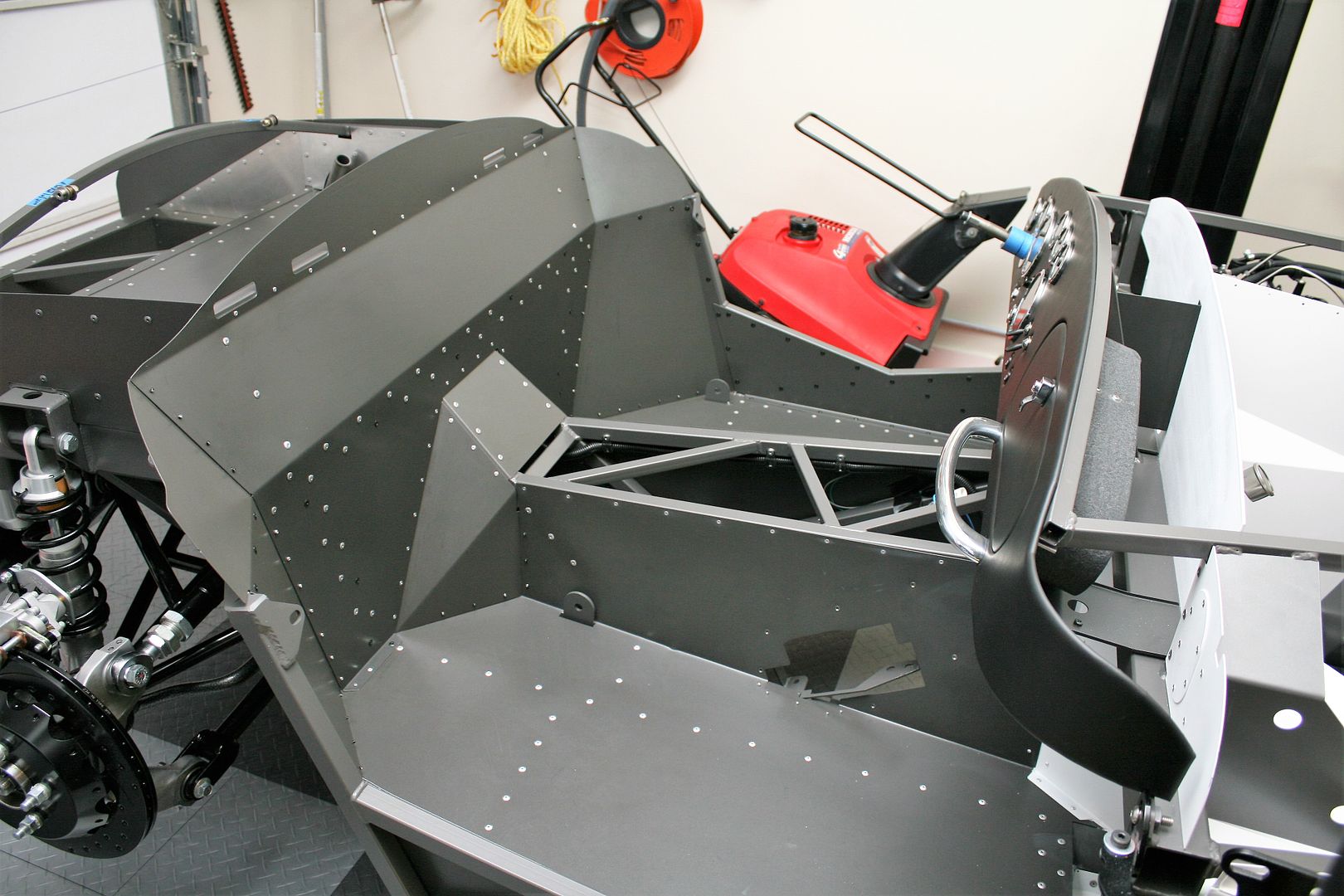
Completed cockpit area. For you warm climate guys, that red thing in the background is something we cold climate guys call a “snow blower.” Fortunately haven't had to use it too much this year. Thought I would use this opportunity to educate those who miss out on the real joy of winter. 
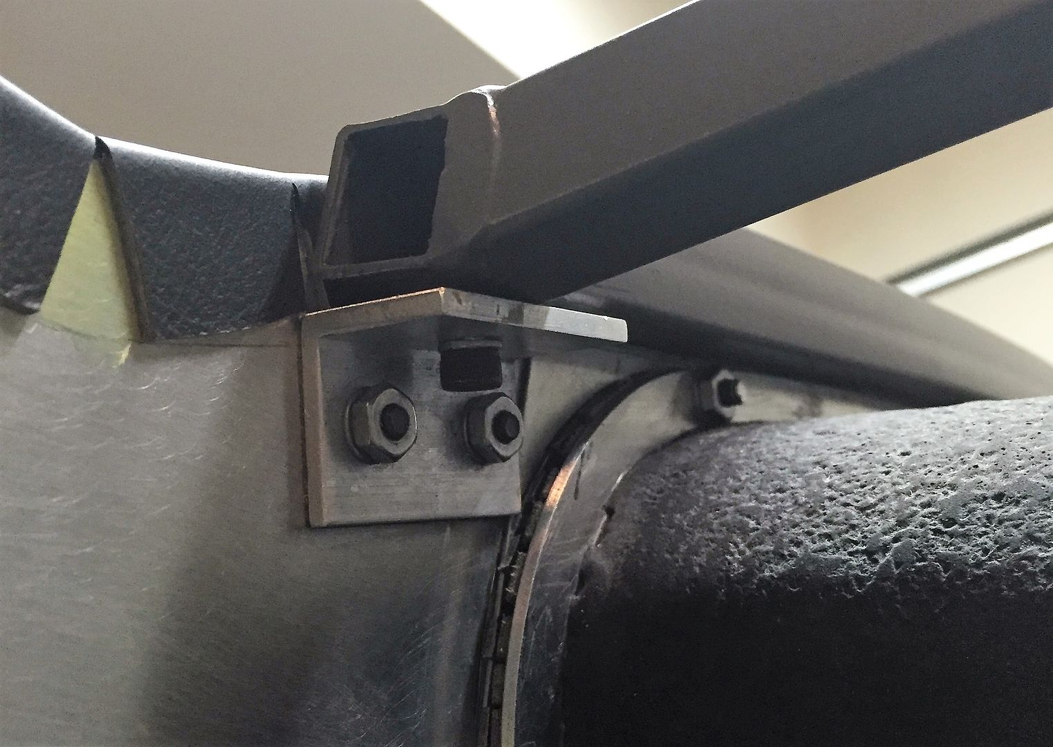
Next I decided to wrap up my dash mounting. In my previous update I showed how I mounted four 90 degree tabs on the back of the instrument panel. Now to give them a matching mounting location on the 3/4 inch dash tube. I located the tabs on the panel to have enough space for a 10-32 nut plate on the dash tube. The dash tube isn’t thick enough to tap threads. A nutsert might work, but finding the location and the proper angle would be quite difficult. So I took some steel nut plates (from McMaster, where else?) and drilled a hole in each end with a countersink. Then attached them to the tabs on the dash with some 10-32 screws, dabbed on some JB Weld, and clamped the dash in the intended location. With the JB Weld cured, removed the screws, removed the dash, added a little more JB Weld around the plates to fill any gaps, then installed two flush rivets into the previously drilled holes. Not going anywhere soon. Four locations look something like this:
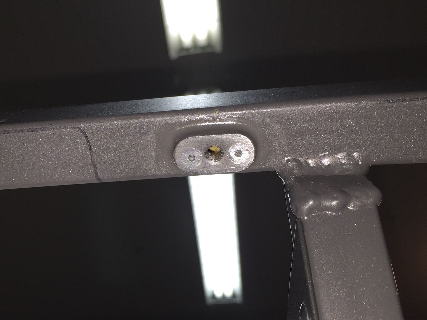
Then installed the dash with longer 10-32 socket head screws into the four mounting locations. Like this one. They're easy enough to reach with a long ball end Allen wrench. I purposely mounted them in locations with a nearly straight access from the bottom.
Last edited by edwardb; 04-01-2016 at 11:06 AM.
Build 1: Mk3 Roadster #5125. Sold 11/08/2014.
Build 2: Mk4 Roadster #7750. Sold 04/10/2017.
Build Thread
Build 3: Mk4 Roadster 20th Anniversary #8674. Sold 09/07/2020.
Build Thread and
Video.
Build 4: Gen 3 Type 65 Coupe #59. Gen 3 Coyote. Legal 03/04/2020.
Build Thread and
Video
Build 5: 35 Hot Rod Truck #138. LS3 and 4L65E auto. Rcvd 01/05/2021. Legal 04/20/2023.
Build Thread. Sold 11/9/2023.
-
03-12-2016, 10:53 AM
#221
Senior Member

This Week’s Update (continued)
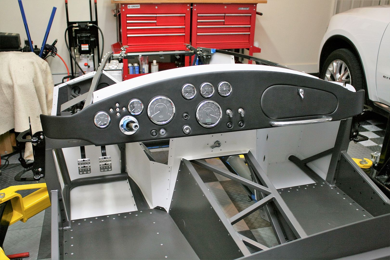
The dash mounting turned out really well. With the top mounts, and the three braces along with bottom (small one each side, wider one in the middle over the tunnel), will be rock solid. I achieved my goal of a strong and serviceable dash mounting without screws through the front. I’m not going to kid though. This method is a little tedious and may not be for everyone. Also one of the reasons I’ll never build one of these in the 300 hours (or whatever) FF advertises. The dash will have to come off one more time for wiring, but looks good sitting in the chassis for now:
My next step was to install the Breeze front battery mount box, and get started on power wiring. Got the box mounted temporarily with clecos. Mark’s instructions are awesome. He even included a right angle grease fitting for the LCA since the battery blocks that location. I don’t remember that from the last time I installed one of these.
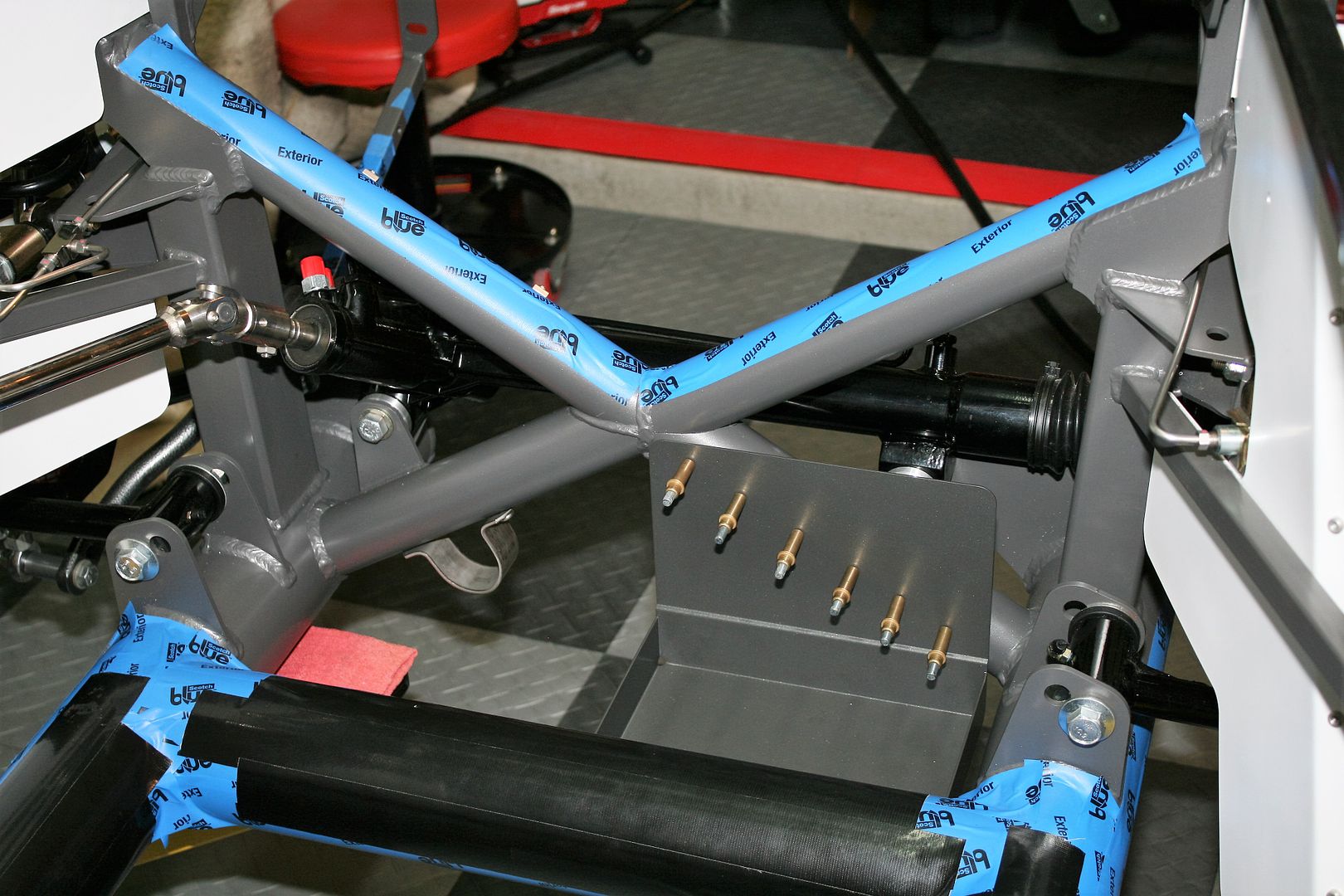
But in the process of installing the battery box, I made a somewhat disturbing discovery. I noticed that a small section of weld was missing from the front x-tube. About 3 inches long. You can see it just above the LH corner of the battery box. I can’t believe I didn’t see this before. I’m not going to dwell on it, because it’s being resolved. I sent a picture to FF using the customer service email address, and expected to follow-up with a phone call later in the day. But in less than an hour, Dan at FF called me instead, and we have a plan to fix. I don’t weld, so will have a welder come to my house to TIG weld the missing location. Dan is having some touch-up paint mixed to match the anniversary color. FF is of course picking up the tab for everything. Dan was great and they are really stepping up. He said the welding is checked multiple times, and especially for these Anniversary kits where some additional checking and clean-up was done. So he couldn't imagine how this was missed. Nonetheless, it was. This area is almost completely hidden by the battery once installed. So however the final repair turns out, it will be gone and mostly forgotten. Setbacks happen during every build. Just need to address and move on, which I plan to do. More wiring ahead.
Last edited by edwardb; 03-12-2016 at 10:56 AM.
Build 1: Mk3 Roadster #5125. Sold 11/08/2014.
Build 2: Mk4 Roadster #7750. Sold 04/10/2017.
Build Thread
Build 3: Mk4 Roadster 20th Anniversary #8674. Sold 09/07/2020.
Build Thread and
Video.
Build 4: Gen 3 Type 65 Coupe #59. Gen 3 Coyote. Legal 03/04/2020.
Build Thread and
Video
Build 5: 35 Hot Rod Truck #138. LS3 and 4L65E auto. Rcvd 01/05/2021. Legal 04/20/2023.
Build Thread. Sold 11/9/2023.
-
03-19-2016, 09:57 AM
#222
I just got my control pack last week. Yikes it felt forever! I'm assuming you received yours too. T
he question I have is where are you going to locate it?
-
03-19-2016, 11:30 AM
#223
Senior Member


Originally Posted by
Oliver27

I just got my control pack last week. Yikes it felt forever! I'm assuming you received yours too. T
he question I have is where are you going to locate it?
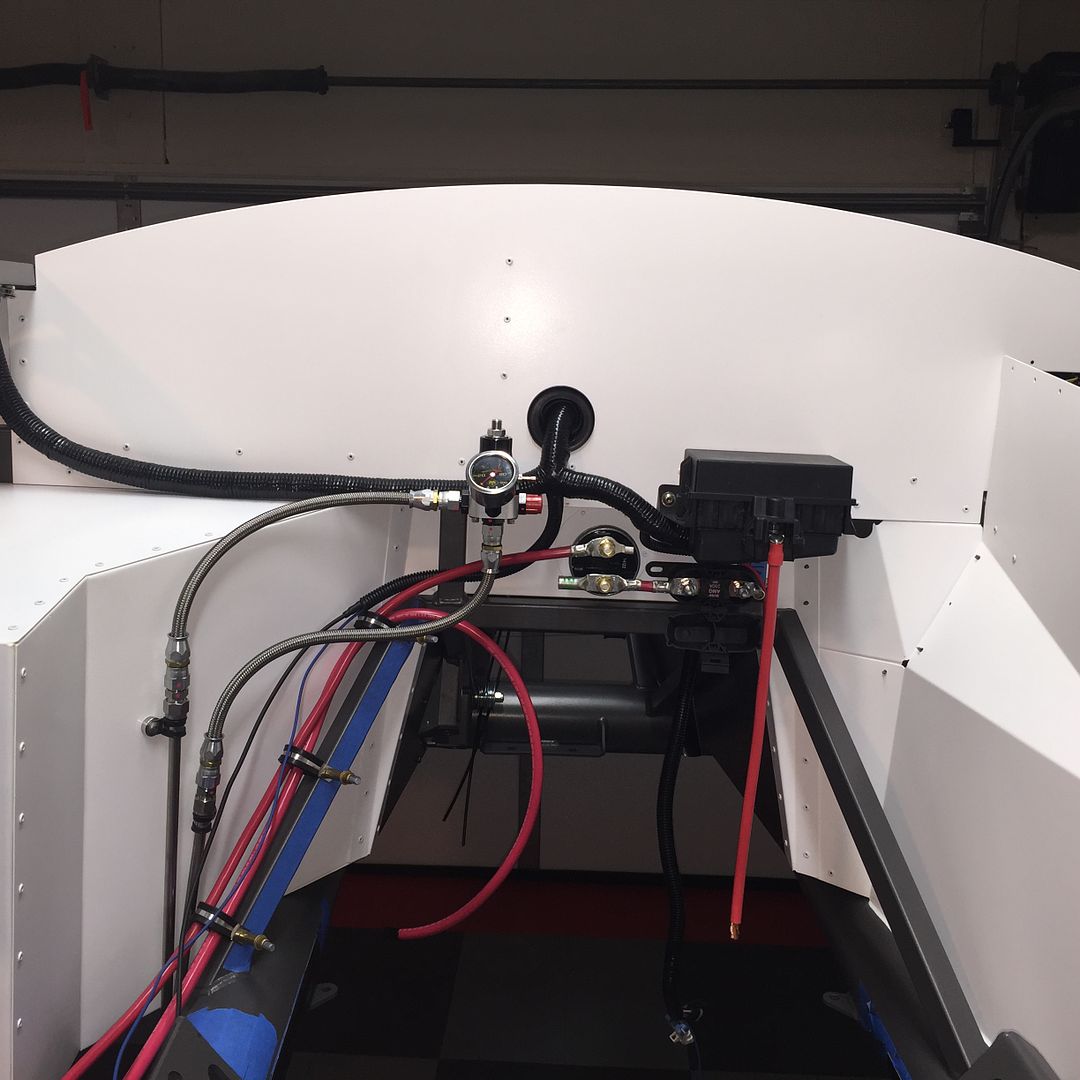
Yes, I have the control pack. It was available along with the engine and related parts when I bought the crate motor package last October. I discussed the new 2015 control pack in some detail, and also my plans for how I'm installing it, earlier in this build thread. Starts on page 2 and goes from there. I know this is a long thread (sorry about that) but what you're asking about is all there. Coincidentally, I am working on finalizing all this at this exact moment. Currently wiring the front mounted battery back to the master disconnect and also to the Coyote PDB. Snapped this pic a few minutes ago before I came in for lunch. Doesn't look very pretty. Just roughing stuff in right now before everything goes in convolute.
Build 1: Mk3 Roadster #5125. Sold 11/08/2014.
Build 2: Mk4 Roadster #7750. Sold 04/10/2017.
Build Thread
Build 3: Mk4 Roadster 20th Anniversary #8674. Sold 09/07/2020.
Build Thread and
Video.
Build 4: Gen 3 Type 65 Coupe #59. Gen 3 Coyote. Legal 03/04/2020.
Build Thread and
Video
Build 5: 35 Hot Rod Truck #138. LS3 and 4L65E auto. Rcvd 01/05/2021. Legal 04/20/2023.
Build Thread. Sold 11/9/2023.
-
03-19-2016, 11:39 AM
#224
PLATNUM Supporting Member


-
03-20-2016, 12:37 PM
#225
Senior Member

Hi Edward,
Quick FYI that may help. I just put the motor/trans in together for mock up and found that with my T56 mag trans. I had to take the shifter off and the alternator. With the motor coming down at a steep angle I couldn't clear the steering with the trans on it.
-
03-20-2016, 03:33 PM
#226
Senior Member


Originally Posted by
Duke

Hi Edward,
Quick FYI that may help. I just put the motor/trans in together for mock up and found that with my T56 mag trans. I had to take the shifter off and the alternator. With the motor coming down at a steep angle I couldn't clear the steering with the trans on it.
Thanks for the heads up. Actually I did my mock-up with the steering column swung out of the way, and plan to do the same when it goes in for real in the next weeks. The alternator cleared OK then. I'm doing a TKO, a little skinnier than a T56, so I'm expecting it will go in without any issue. My last one did. But I do know the whole transmission is in a slighter different location with a Coyote compared to the SBF from before. Hopefully the shifter will clear OK. If not, easy enough to pop off.
Build 1: Mk3 Roadster #5125. Sold 11/08/2014.
Build 2: Mk4 Roadster #7750. Sold 04/10/2017.
Build Thread
Build 3: Mk4 Roadster 20th Anniversary #8674. Sold 09/07/2020.
Build Thread and
Video.
Build 4: Gen 3 Type 65 Coupe #59. Gen 3 Coyote. Legal 03/04/2020.
Build Thread and
Video
Build 5: 35 Hot Rod Truck #138. LS3 and 4L65E auto. Rcvd 01/05/2021. Legal 04/20/2023.
Build Thread. Sold 11/9/2023.
-
03-23-2016, 09:56 AM
#227

Steve >> aka: GoDadGo

T r u l y a m a z i n g w o r k !
-
Post Thanks / Like - 0 Thanks, 1 Likes
-
03-23-2016, 04:06 PM
#228
Senior Member


Originally Posted by
edwardb

These are the already mentioned clutch “bottom” and clutch “top” switches provided. They have dedicated legs on the harness. According to Ford Racing tech, they are mandatory. The bottom switch is required as a starter interlock. The top switch apparently triggers some reaction by the PCM to the engine when the clutch is started down. I’m not going to question them. I will install but thinking not to use these exact switches. Measuring them, they’re just 2-wire NO and NC contact switches. I’m thinking I can use the typical switches we use on our builds, like the one on the right. The top switch can be mounted in the Wilwood box just like a brake switch, and in fact I already made and installed a bracket like that on the clutch side anyway. Then just need to figure out how to have a similar switch at the bottom of the clutch stroke. Stay tuned for that as well.
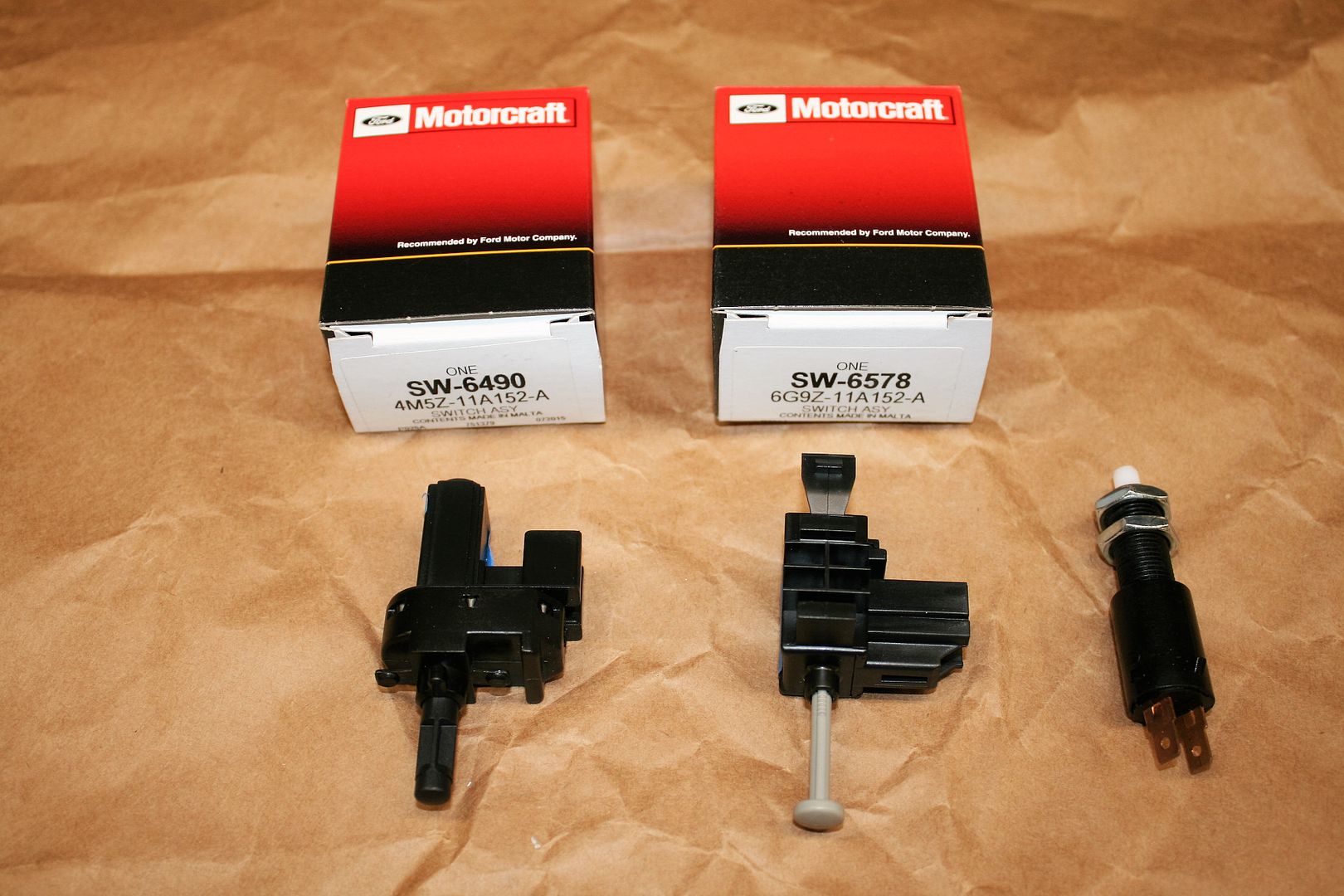
Hi Edward, I'm fabricating the clutch switches at the moment and thought I would pass along what I'm doing. I'm just using brake light switches mounted one on top of the other in similar fashion to how the FFR brake light switch is mounted. Both switches are looking for contact when the clutch is pressed in. Putting these two in front of the clutch solves the problem, when the clutch is pressed in it triggers both circuits to close, similar to a brake light. A simple double long bracket with both of them screwed in will work just fine. It's a lot easier than trying to figure out clutch pedal travel for the grey plunger to trigger 
http://www.amazon.com/Borg-Warner-S2..._detailpages00
-
03-23-2016, 04:47 PM
#229
Senior Member


Originally Posted by
Duke

Hi Edward, I'm fabricating the clutch switches at the moment and thought I would pass along what I'm doing. I'm just using brake light switches mounted one on top of the other in similar fashion to how the FFR brake light switch is mounted. Both switches are looking for contact when the clutch is pressed in. Putting these two in front of the clutch solves the problem, when the clutch is pressed in it triggers both circuits to close, similar to a brake light. A simple double long bracket with both of them screwed in will work just fine. It's a lot easier than trying to figure out clutch pedal travel for the grey plunger to trigger

Thanks for the input. There's another forum member (jcjorgensen) also trying to sort out the clutch switch thing. Maybe you've seen the posts. He tried it with the bottom clutch always closed, just to eliminate having to figure out a way to actuate it, and got some strange behavior. As I said in my build thread you quoted, I've already fabricated a piece just like FF supplies for the brake light and installed it on the clutch pedal, with the same kind of brake light switch FF supplies and you linked to. It's installed and working. So top switch done. For the bottom switch, I know it's maybe a pain, but I'm planning to figure out a way to have the switch at the bottom of the clutch stroke. From a safety standpoint, I want the clutch all the way down before the PCM will allow the start. In addition, I think it's possible the designers want to differentiate between the two clutch positions. Of course I don't know that for a fact, but when I asked Ford Racing tech support about whether the speed dial was needed for the new 2015 control pack, they responded no and said hardware and software changes had been made to solve the idle/stall issue of the previous crate control pack. He specifically cited the top and bottom clutch switches as part of that solution. My takeaway is to figure out a way to make them work as designed. I'm nearly positive I won't use the Ford supplied switch for the bottom either. There's just no good way I can see to integrate it into the Wilwood pedal. Right now I'm looking at using a roller lever micro switch, bracketed somehow at the bottom of the clutch pedal throw. I'm a couple steps away in my build from working on it in earnest. I'll be interested to see what you come up with, and specifically how it acts when you get it running and driving.
Last edited by edwardb; 07-20-2020 at 09:50 PM.
Build 1: Mk3 Roadster #5125. Sold 11/08/2014.
Build 2: Mk4 Roadster #7750. Sold 04/10/2017.
Build Thread
Build 3: Mk4 Roadster 20th Anniversary #8674. Sold 09/07/2020.
Build Thread and
Video.
Build 4: Gen 3 Type 65 Coupe #59. Gen 3 Coyote. Legal 03/04/2020.
Build Thread and
Video
Build 5: 35 Hot Rod Truck #138. LS3 and 4L65E auto. Rcvd 01/05/2021. Legal 04/20/2023.
Build Thread. Sold 11/9/2023.
-
03-23-2016, 07:51 PM
#230
Senior Member

Power Wiring Completed
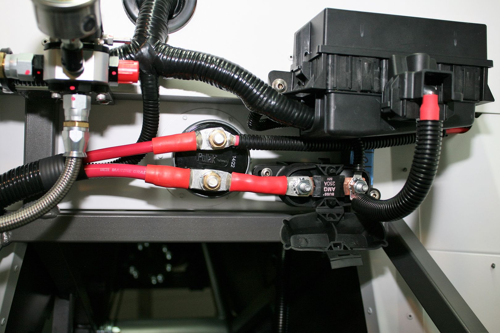
Today I finally finished the power wiring. Took longer than I planned, but what’s new about that. I did a front mount Breeze battery box on my last build and was very happy with it. So once I confirmed the Coyote installation would have enough room, did the same for this build. I received the front mount kit from Mark some weeks ago, and had it powder coated with all the rest of the parts. Also for the last build, I spent a lot of time looking at other builds and how the power wiring was done. Came up with my own spin on lots of good ideas, and that’s what I did and it has worked very well. This build is almost a carbon copy. The +12 volt battery wire is routed along the chassis to the master disconnect below dash center. Off the switched side is a large wire back to the starter, and another smaller wire to the RF panel and harness behind the dash. The battery ground is routed to the chassis near the battery. Pretty simple and straightforward. Note the firewall mounted solenoid is not used in this arrangement. With a mini starter the solenoid is not required, and the master disconnect serves as a gathering point for the main power wires. But in this case was the added work of integrating the Coyote Power Distribution Box (PDB) into the power wiring scheme.
I talked about this some earlier in the build thread. The 2015 Coyote controls pack has a much different PDB than the previous version. I determined early on, based on the size and configuration of the PDB, as well as the wiring harness, that it had to go in the engine compartment. Not behind the dash as usually the case for the previous version. With that determined, now how to get power to it. The controls pack comes with a long #4 power cable and a smaller ground that is intended to be taken directly to the battery. I saw no reason to use this if I supplied adequate power from the normal power wiring. I took the power leads from the Coyote PDB directly to the power at the master disconnect. There are four separate ground leads in the Coyote harness. Those Ford guys were pretty serious about getting a good ground! Three will go to chassis ground where the harness ends up. But I chose to home run the one lead back to the battery ground itself, as the instructions showed. Just to eliminate all doubt. I’ll provide more details along with the pictures.
First up is the battery. I chose an Optima group 51 yellow top, just like my last build. This is Optima part number 8071-167. That’s important because of the location of the positive and negative posts. They also sell a reversed version, but that puts the positive post very close the chassis x-frame. I strongly recommend avoiding this. Here you can see the start of the #2 battery cables I installed. The kit comes with #4 cables, which I used on my last build and for the relatively short runs with the front mounted battery, they have been fine. But since I eliminated the separate #4 cable provided with the Coyote controls pack, I chose to go to the larger size to carry both the normal power plus the Coyote PDB. I picked up the #2 cable at West Marine. It’s very nice quality marine grade cable. Not cheap, and probably overkill. But they sell it by the foot so I got the exact amount I needed. Note also here the chassis ground location. The smaller ground lead is from the Coyote PDB mentioned previously. When I mocked up the Coyote in the engine bay, I measured the location of the front crankshaft pulley. These cable locations clear the pulley by about 1-1/2 inches. And for you guys that notice such things, I do have the battery ground installed. But the positive battery lead I just set in place for this picture. While working on the build, I have it disconnected and the cap over the post.

One other thing you don’t see in this picture, and it’s a pretty big deal. The missing weld on the x-frame. Refer to my previous update showing the missing weld. It’s hard to see here because it’s partly behind the battery. But it’s been welded and the powder coat touched up. If you didn’t know it had been repaired, you wouldn’t know it. Even if I pointed it out, you probably wouldn’t see it. That’s huge and a giant weight off my mind. I didn’t take any pictures after the weld was completed, because it hurt just to look at it. There was damage 1-2 inches each side of the weld. But now done and gone. I’ll post about the touch-up paint at the end of this update. Factory Five has stepped up and done what was necessary to get this fixed, so kudos to them.
Back to power wiring. Here I routed the wiring in convolute down the chassis tube with a breakout for the starter wires. I measured the exact location for the two wires while the engine was mocked up, so these should bolt right into place when the engine goes back in. The smaller wire is the blue start signal wire. I put a piece of shrink sleeving around it. This wire is from the Coyote harness because the PCM controls the start process in this setup. This wire originally was at the engine end of the harness. I stripped back the harness enough to get it to the firewall so it could go to the starter along with the starter battery wire. Just cleaner that way.
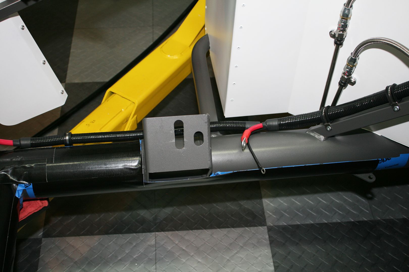
Then up to the master disconnect and Coyote PDB. Here you can see a branch of the Coyote harness going to the dash area. There it gets connections for the fuel pump, start circuit, DBW, clutch switches, etc. The branch on the LH side along the top of the PS footbox goes to the PCM, engine, fan, etc.
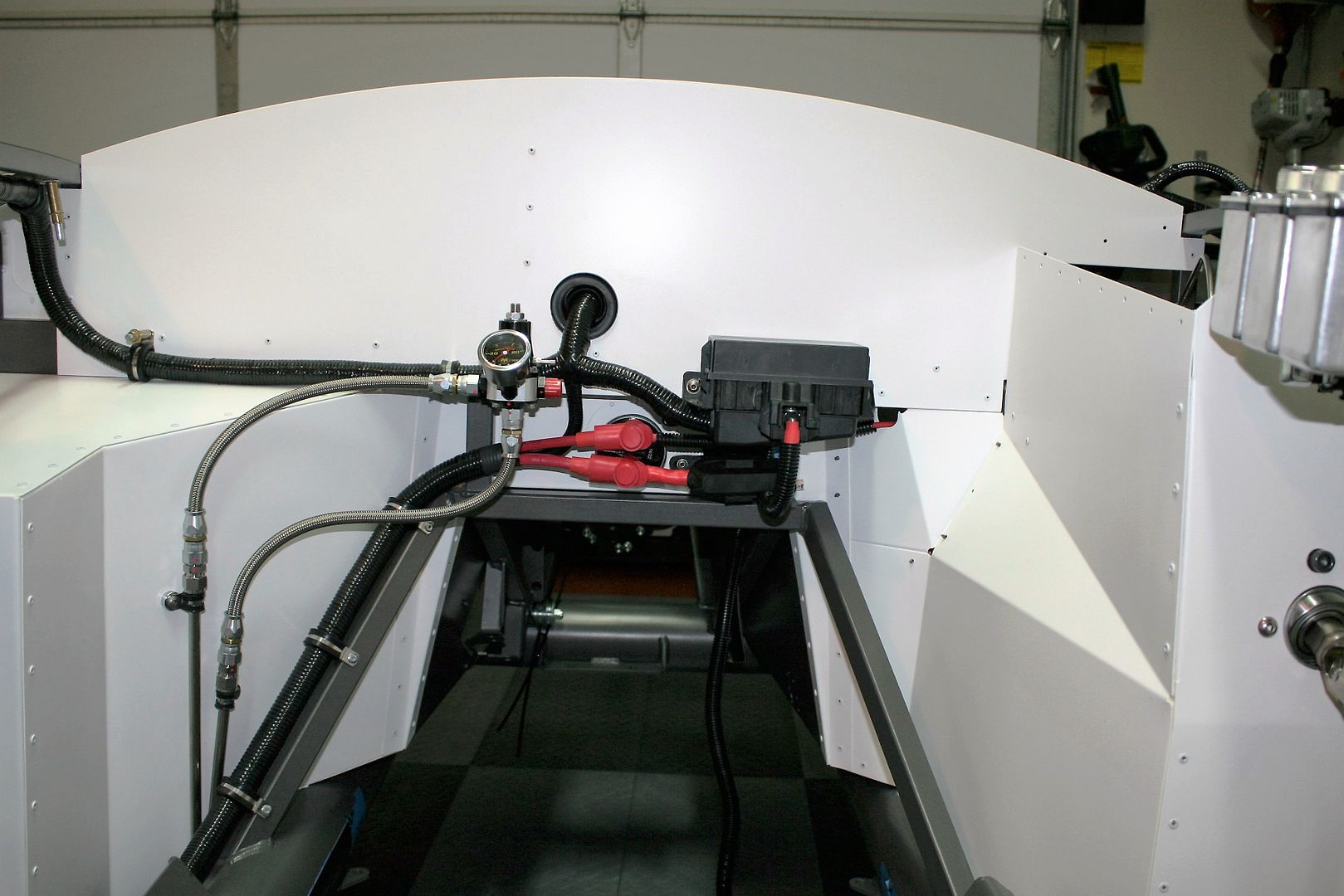
This is a closer view of the finished power wiring. Doesn’t look all that great, but this whole area is behind the engine and below the body cowl. No way to make it very pretty short of covering it all up, but I’m not going to bother with that. The only thing not done here is the 8 gauge wire poking through the hole into the dash area. That’s the main power feed to the RF harness. More work to be done there. That hole also needs to be enlarged because that's also where the rear harness leg needs to go through.
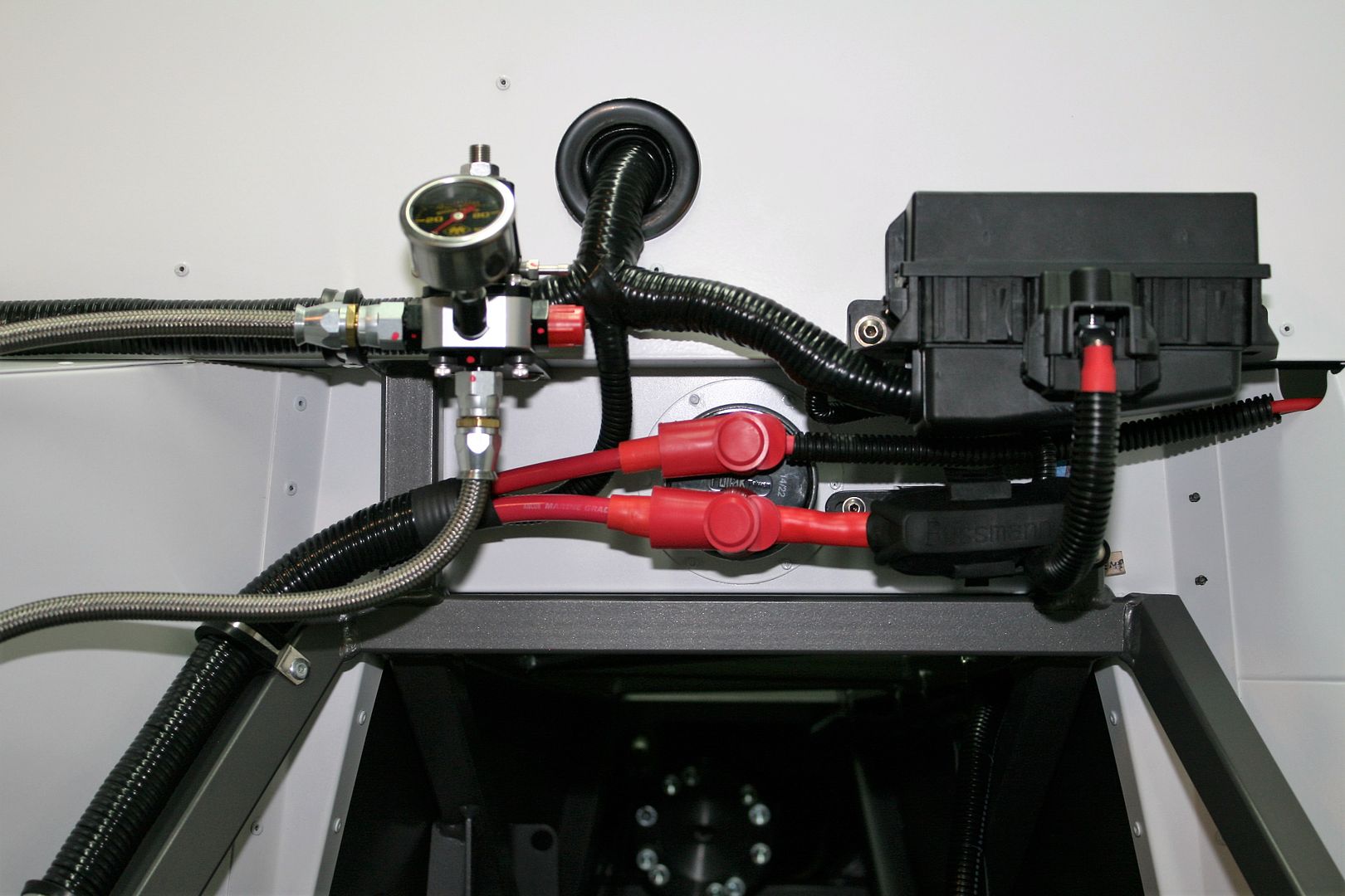
Here is a picture of the power wiring area with a couple of the covers off so you can see the wiring layout I ended up with. The main battery power is the larger #2 cable on the lower post of the disconnect. The starter wire is on the top post going to the left, and the RF harness feed going to the right. So switching on the disconnect makes power available to the starter and RF harness. The smaller leg coming out of the Coyote harness next to the red cap on the regulator is the chassis ground mentioned earlier that goes to the front and the blue starter wire going to the starter. The large lead coming off the hot side of the switch is a #4 cable powering the Coyote PDB. It goes through the Ford supplied 250 amp fuse, and then another short #4 cable going to the front power tap on the PDB. I’m not completely sure why the 250 amp fuse. Nothing in the circuit should draw anywhere near that kind of current. IMO something is going to need to be dead shorted to pop it. But I guess that’s the point. Anyway, our friends at Ford thought it was necessary so I used it. I made a little bracket to hold it in the position shown. There is a second +12V power lead in the Coyote harness through a mating connector. But when you take the harness apart, it’s attached to the main power lead. So I routed it to the fused side as well. You can just see the smaller lead under the PDB.
So obviously with this wiring arrangement the Coyote PDB will always be on as long as the battery is connected. The instructions say this is necessary to store self-learned programming and error codes. A minor side benefit is the harness behind the dash includes an available constant +12V lead. Ford labels it HAAT, or Hot At All Times. Have to love it. I’m going to use that for the clock and also the speedo GPS. Speedhut provides a power wire that supposedly makes the GPS wake up more quickly if current is always applied. But with the PDB always powered, would switching off the master disconnect stop a running engine? My educated guess is probably not. The alternator would likely still keep everything alive. But the engine would not start with the master disconnect off, for a number of reasons. So I’m OK with that. I’m putting fuel pump and EFI switches under the dash, so either of those would kill a running engine if needed. Not to mention the ignition switch.
Last edited by edwardb; 03-24-2016 at 07:51 AM.
Build 1: Mk3 Roadster #5125. Sold 11/08/2014.
Build 2: Mk4 Roadster #7750. Sold 04/10/2017.
Build Thread
Build 3: Mk4 Roadster 20th Anniversary #8674. Sold 09/07/2020.
Build Thread and
Video.
Build 4: Gen 3 Type 65 Coupe #59. Gen 3 Coyote. Legal 03/04/2020.
Build Thread and
Video
Build 5: 35 Hot Rod Truck #138. LS3 and 4L65E auto. Rcvd 01/05/2021. Legal 04/20/2023.
Build Thread. Sold 11/9/2023.
-
03-23-2016, 07:52 PM
#231
Senior Member

Power Wiring Completed (continued)
All of the #2 and #4 lugs, battery terminals, and triple wall sleeving used was from DelCity. Great supplier. For my last build, for all these larger connectors I used their Fusion products or solder slugs. However, for DD's and most factory built cables these kinds of connections are typically crimped. But because of the large cable and connectors the crimpers and dies are typically pretty expensive. Certainly too expensive for occasional home use IMO. But I ran across a cheap hydraulic crimper somewhere online (don't remember where...) that had a bunch of positive reviews. So I thought I would give it a try. Model number is YQK70. They're all over the place. I found it for $37 including shipping on eBay. That's just crazy. It's a bit on the cheap side (think Harbor Freight quality) and I can't say it will last a lifetime. But it came with a number of dies, and for the larger stuff (#2, #4 and #8) it does a decent job. The crimps are six-sided and seem very solid. I bought a few extra lugs and practiced/experimented before committing to the final parts. I did pull tests and cut some in half. Solid copper through the section. I went ahead and still used the Fusion (solder) connectors for the battery terminals. But all the rest of the wiring shown here was done with this crimper. Something to check if you're interested.
Right before I took these pics I did a little checking. With the battery leads connected (and all loose wire ends accounted for!) with a test light I could find +12 volts in all the right places. The master disconnect is switching the right stuff. I also checked the aforementioned HAAT wire in the Coyote harness behind the dash. It's alive. So power is getting through the Coyote PDB and harness. Baby steps but I'll take it for now.
I’ll be wrapping up a few more details on the wiring and then start masking and spray my Lizard Skin sound and heat insulation. By then I should have the transmission and will drop in the engine. Still have dash and RF harness wiring to finish. But could first start be too much longer after that?
Last update is the touch-up paint. After some searching, I found a company in Texas that packages touch-up paint for powder coat and include some of the Tiger Drylac colors. I contacted them about the specific Tiger Drylac DB 703 Glimmer, 49/84340 power coat used on the Anniversary frame. They said yes they could provide it. Received it yesterday and the match is perfect. I don't think you could find the repair. I'm impressed (and relieved...). Here's a picture of the spray can with the company name and website. $15 plus shipping. Not bad. That is officially my last mention of the missed weld and repair. It’s done and over with.
Last edited by edwardb; 03-23-2016 at 10:41 PM.
Build 1: Mk3 Roadster #5125. Sold 11/08/2014.
Build 2: Mk4 Roadster #7750. Sold 04/10/2017.
Build Thread
Build 3: Mk4 Roadster 20th Anniversary #8674. Sold 09/07/2020.
Build Thread and
Video.
Build 4: Gen 3 Type 65 Coupe #59. Gen 3 Coyote. Legal 03/04/2020.
Build Thread and
Video
Build 5: 35 Hot Rod Truck #138. LS3 and 4L65E auto. Rcvd 01/05/2021. Legal 04/20/2023.
Build Thread. Sold 11/9/2023.
-
03-24-2016, 07:03 PM
#232
Edward,
Your routing is second to none, looks fantastic!!
-
03-24-2016, 08:16 PM
#233
Senior Member


Originally Posted by
jcjorgensen

Edward,
Your routing is second to none, looks fantastic!!
There are lots of great wiring jobs out there, but I appreciate the compliment. Thanks!
Build 1: Mk3 Roadster #5125. Sold 11/08/2014.
Build 2: Mk4 Roadster #7750. Sold 04/10/2017.
Build Thread
Build 3: Mk4 Roadster 20th Anniversary #8674. Sold 09/07/2020.
Build Thread and
Video.
Build 4: Gen 3 Type 65 Coupe #59. Gen 3 Coyote. Legal 03/04/2020.
Build Thread and
Video
Build 5: 35 Hot Rod Truck #138. LS3 and 4L65E auto. Rcvd 01/05/2021. Legal 04/20/2023.
Build Thread. Sold 11/9/2023.
-
03-24-2016, 10:54 PM
#234
Paul, is that all you do is build. You are so organized. I always go to your build site first if I need an answer. Thanks. Looks great. Wish I still had Coyote plans but that went away when Washington State change there license requirements. May need some of that paint. Nice find! Jim
-
03-25-2016, 06:13 AM
#235
Senior Member


Originally Posted by
RR20AC

Paul, is that all you do is build? Jim
Not exactly, but needless to say I have more time now that I'm retired. It's been just over a year now. I think it's going to work out. 
Build 1: Mk3 Roadster #5125. Sold 11/08/2014.
Build 2: Mk4 Roadster #7750. Sold 04/10/2017.
Build Thread
Build 3: Mk4 Roadster 20th Anniversary #8674. Sold 09/07/2020.
Build Thread and
Video.
Build 4: Gen 3 Type 65 Coupe #59. Gen 3 Coyote. Legal 03/04/2020.
Build Thread and
Video
Build 5: 35 Hot Rod Truck #138. LS3 and 4L65E auto. Rcvd 01/05/2021. Legal 04/20/2023.
Build Thread. Sold 11/9/2023.
-
03-31-2016, 09:20 PM
#236
Senior Member

Lizard Skin Insulation Completed
Yesterday I sprayed the final coats of the Lizard Skin and removed all the masking. Today it was dry enough to finish cleaning up, start putting on some parts for the final time, and take a few pics to share. I did a pretty extensive write-up about the Lizard Skin process and results for my last build. So not going to repeat it all. The thread is here: http://www.ffcars.com/forums/17-fact...xperience.html. I’m happy with the final result, and based on my first two builds and actual driving experience, the stuff does the job. In addition to the sound and heat properties, I really like how it seals everything up. There’s no denying though it’s a lot of work. From a pure hours standpoint I’ll bet no more than fitting, peeling, and sticking one of the other more traditional products. But the hours masking, then getting ready for spraying (especially if you’re not really set up for it, which I’m not), and cleaning up afterwards is some effort. But now that it’s done, I would do it again.
First up was to install the last couple panels. I still had two left on the driver’s side footbox. The outside top and side will be saved until the body is ready to go on. Not pictured, but another step is to fill any gaps between the aluminum panels, the frame, around seat belt tabs, etc. The Lizard Skin doesn’t stick well to silicone caulk that a lot of guys use. There are several seam sealer products that work well. For this build I used grey and white Marine Tex epoxy. The white matched the white aluminum panels nicely. The grey is really more black, but still worked OK. I put tape where there were any gaps, usually on the finished side, filled with the Marine Tex epoxy, then removed the tape after it set up. Left nice clean filled joints. With the Lizard Skin added over top on the inside, should be good.
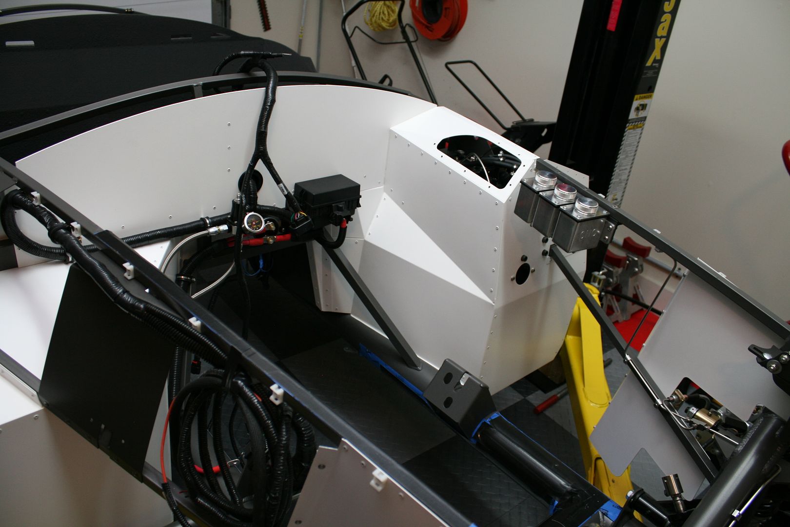
I took a DA to all the panels that would get Lizard Skin and then did all the masking. Pretty much an all-day process. This was ready to spray with the exception of some more drop cloths I had on the floor and on the garage door.
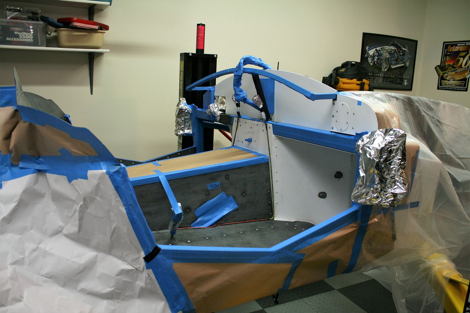
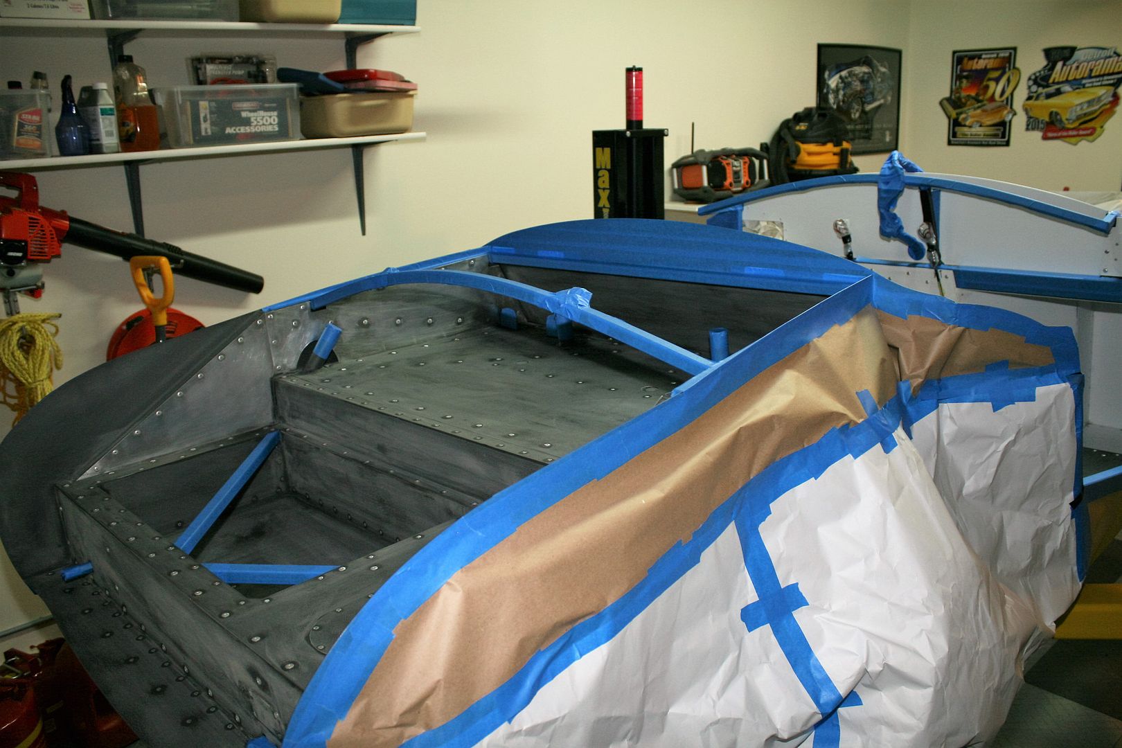
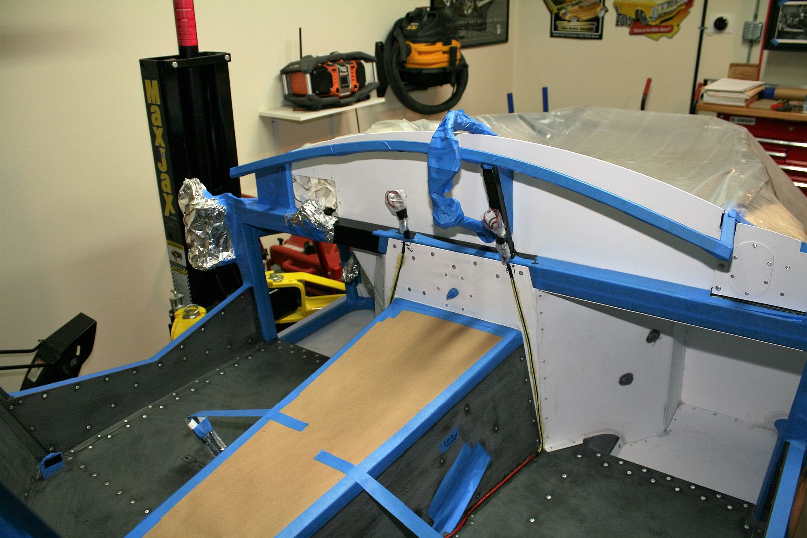
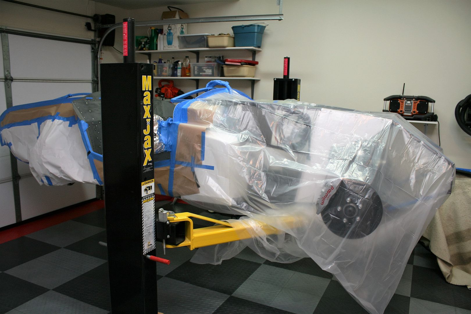
Note I left the Coyote harness in. I didn't feel like taking the power wiring apart and the harness back out (again). I just wrapped it with tape and sprayed around it. Also visible in these pictures are the wiring harnesses for the heated seats. This is exactly how I’ve done the last two builds. Located the connectors and relays for under the seats, then routed the wires along the inside corners of the cockpit up to the dash area where I mounted the switches. I used a little contact cement to initially hold the wires in place. The wires end up buried in the insulation and carpet and completely disappear. These are the CobraHeat heaters mentioned in a previous update. The supplied harnesses aren’t long enough to be installed this way, so it’s necessary to stretch them a bit. In the process, also changed the power wires to enter at the dash switches rather than at the seats the way they’re wired. These means it's only necessary to have three wires between the seats and the switches.
Last edited by edwardb; 03-31-2016 at 09:35 PM.
Build 1: Mk3 Roadster #5125. Sold 11/08/2014.
Build 2: Mk4 Roadster #7750. Sold 04/10/2017.
Build Thread
Build 3: Mk4 Roadster 20th Anniversary #8674. Sold 09/07/2020.
Build Thread and
Video.
Build 4: Gen 3 Type 65 Coupe #59. Gen 3 Coyote. Legal 03/04/2020.
Build Thread and
Video
Build 5: 35 Hot Rod Truck #138. LS3 and 4L65E auto. Rcvd 01/05/2021. Legal 04/20/2023.
Build Thread. Sold 11/9/2023.
-
03-31-2016, 09:21 PM
#237
Senior Member

Lizard Skin Insulation Completed (continued)
I used the Lizard Skin undercoat gun as before. It works pretty well with the settings I describe in the detailed thread. But the stuff does sling everywhere. You cannot have too many drop cloths. As the Lizard Skin write-up describes, the sound insulation (SC) product is sprayed first. Here I did two coats in the trunk and cockpit. I got a little heavy handed trying to make sure I had plenty in the footboxes and managed to get it too thick and it started sagging and running. Took a little post spray clean-up and touch-up. Turned out OK, but not my finest hour… Then the next day I sprayed two coats of the ceramic heat insulation (CI) only in the cockpit. I tried to make sure especially the footboxes got a full heavy coats, and this time without making a mess. Worked out OK. Just like in the last builds, used pretty much all of the 2-gallon pail of each product. This is how it looks now:
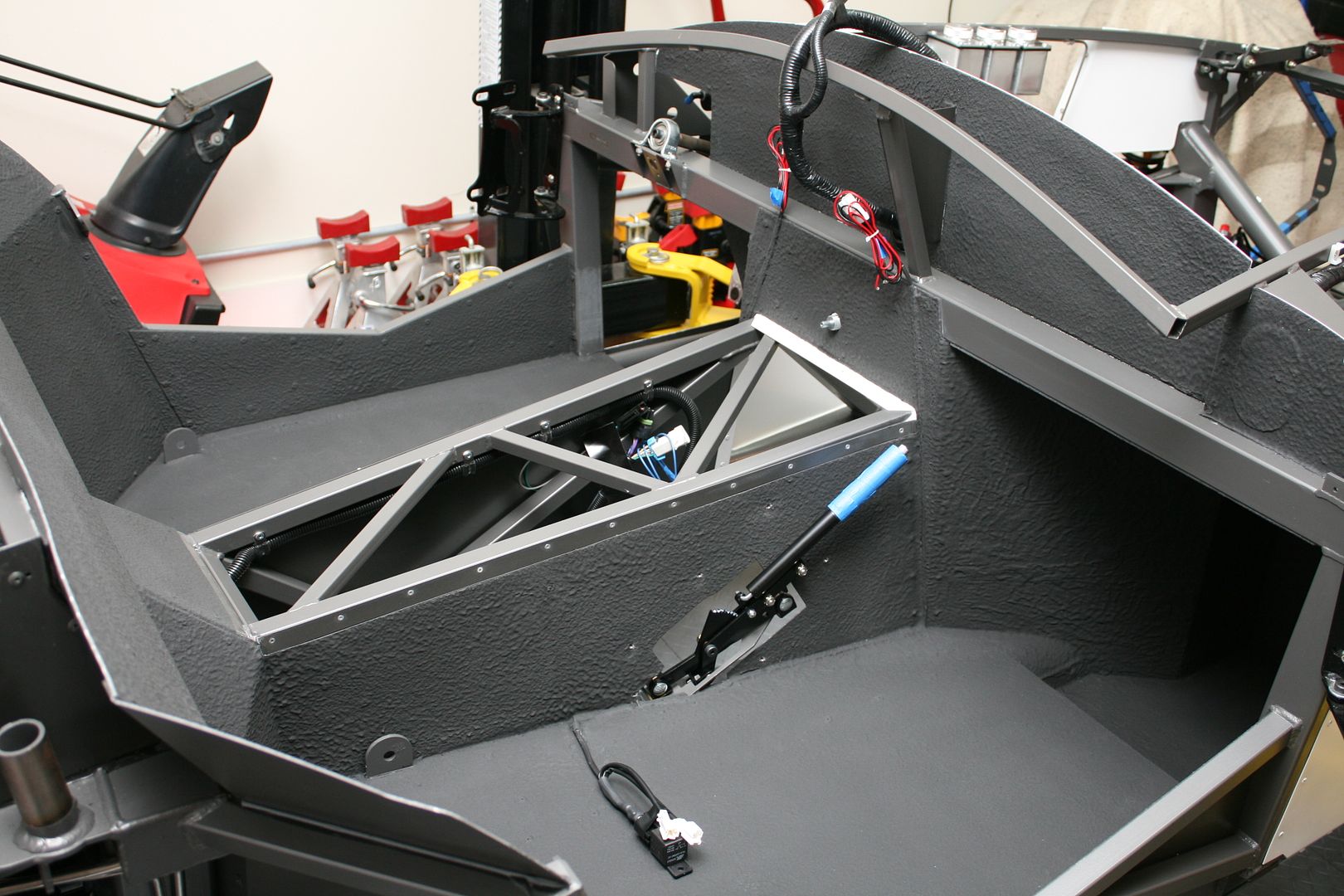
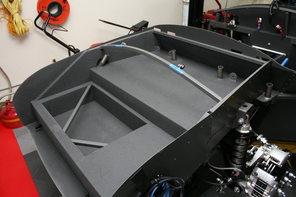
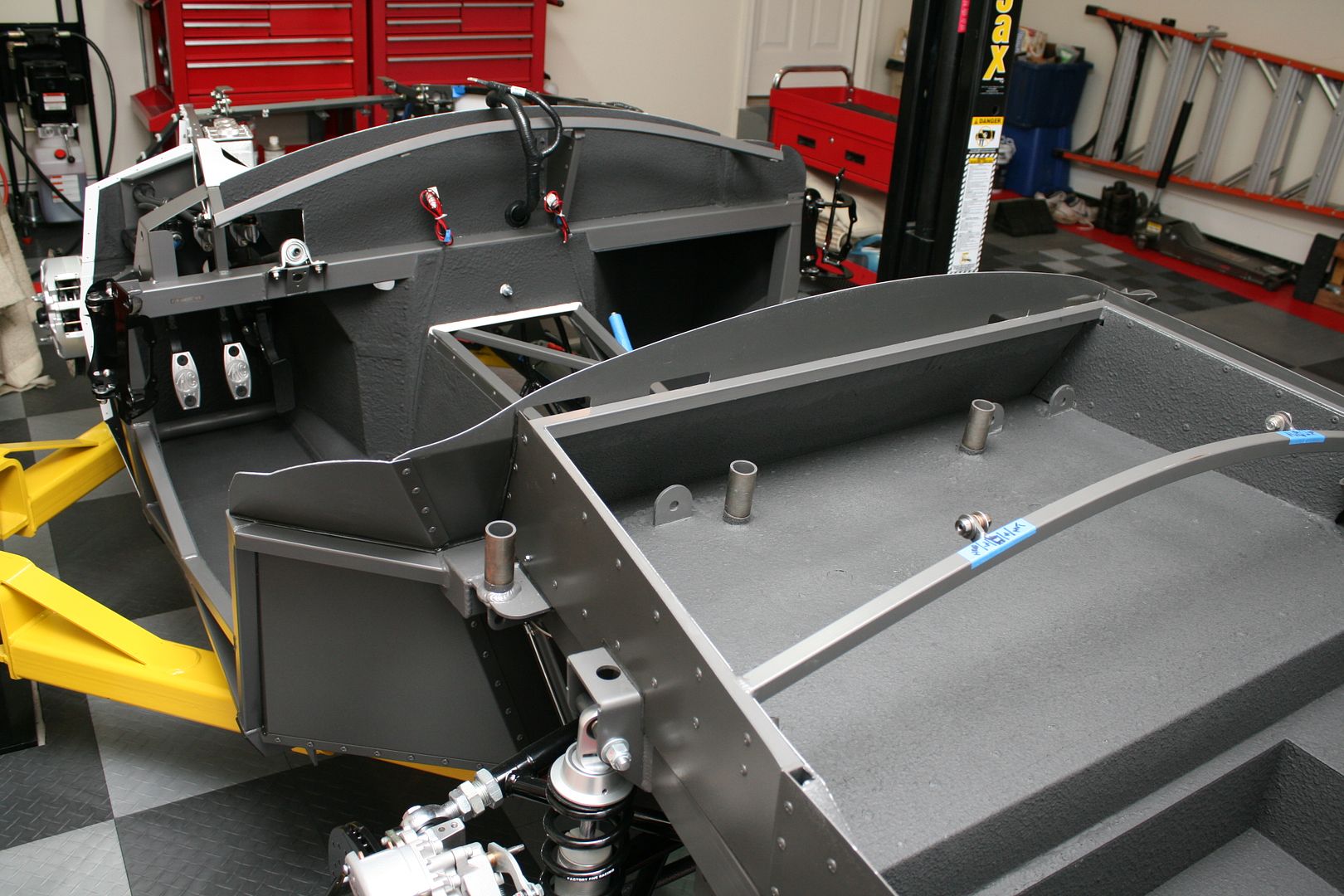
I put the e-brake handle back in for hopefully the last time. Also installed the DBW assembly (accelerator) and brake and clutch pedals. These are the AC pedals from Forte that bolt directly onto the Wilwood pedal arms. They look good plus are a bit narrower than the Wilwood pedals. It’s hard to judge from this picture, but there’s 1-1/2 inches from the RH side of the accelerator pedal to the footbox wall. Then 2 inches from the LH side of the accelerator pedal to the brake pedal. I’m very happy with this spacing, and very similar to my previous SBF builds. It is possible to have decent pedal space with a Coyote. Thanks again to 2bking for his outstanding footbox mod design.
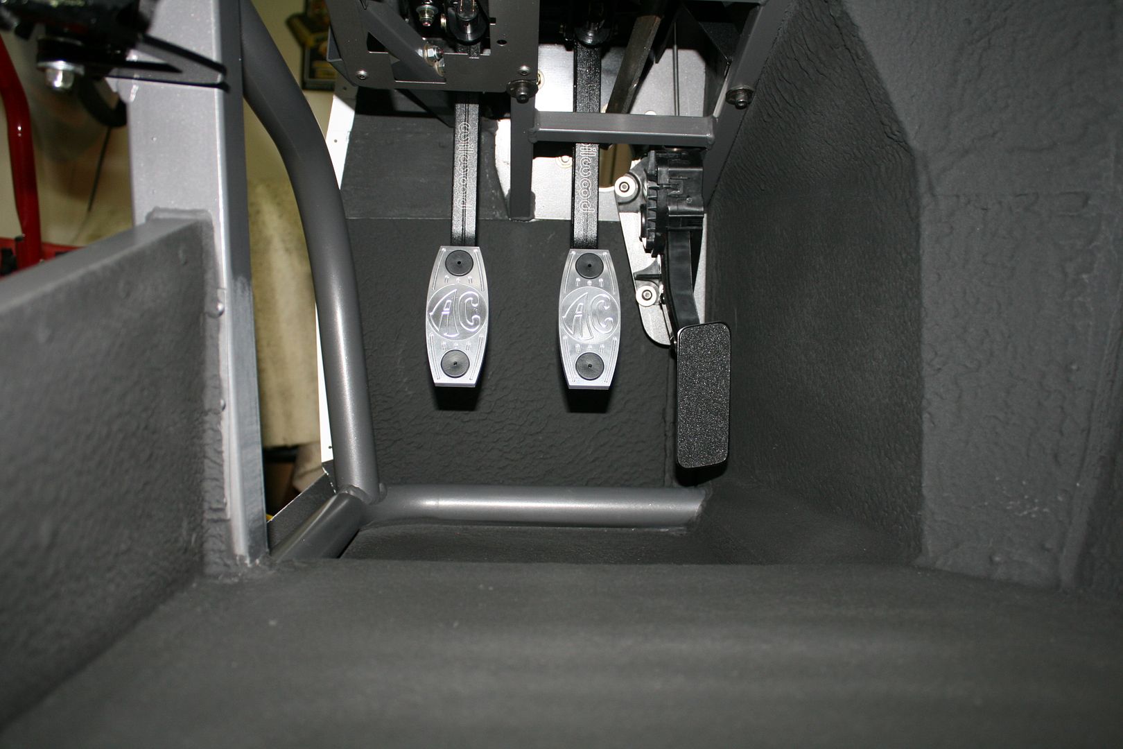
Now I’m full on into electrical wiring, including the dash and installing the RF harness. Plus I'm taking #7750 out of storage next week and will get it ready for another great driving season. 
Last edited by edwardb; 04-01-2016 at 11:07 AM.
Build 1: Mk3 Roadster #5125. Sold 11/08/2014.
Build 2: Mk4 Roadster #7750. Sold 04/10/2017.
Build Thread
Build 3: Mk4 Roadster 20th Anniversary #8674. Sold 09/07/2020.
Build Thread and
Video.
Build 4: Gen 3 Type 65 Coupe #59. Gen 3 Coyote. Legal 03/04/2020.
Build Thread and
Video
Build 5: 35 Hot Rod Truck #138. LS3 and 4L65E auto. Rcvd 01/05/2021. Legal 04/20/2023.
Build Thread. Sold 11/9/2023.
-
04-01-2016, 10:32 AM
#238
cobra Handler

That was very cool the way you ran your main battery power wiring scheme. I like that a lot especially the placement of the cutoff switch and the front mounted battery and wiring in that area. There are so many ways to do it but I haven't seen that one. Pretty work!
Thanks,
WEK.
FFR MkIII 302 (ATK), EFI 75mm TB with custom box plenum chamber, 24# injectors, 4 tube BBK ceramic, cold air sys, alum flywheel, crane roller rockers, T5, Wilwood pedals, custom five link with Watt's link, 4 rotors, coil overs, power steering with Heidt valve, alum FFR rad, driver's crash bar mod, mini dead pedal mod, quick release steering wheel hub #6046
-
04-01-2016, 12:57 PM
#239
Nice Paul, l will be going with the lizard skin too per your advice. I am going to need some of that matching chassis paint to paint my brake and fuel lines. I saw the can but not sure where you got it. Thanks for the great updates. Jim
-
04-01-2016, 02:20 PM
#240
Senior Member


Originally Posted by
RR20AC

Nice Paul, l will be going with the lizard skin too per your advice. I am going to need some of that matching chassis paint to paint my brake and fuel lines. I saw the can but not sure where you got it. Thanks for the great updates. Jim
Good luck with the Lizard Skin. I just put the touch-up paint picture as a thumbnail. If you click the pic you can see the details on the can. The website is http://www.lowvolumepowder.com/. The color isn't showing on their website, but I sent an email and received a quick response with the order info. Or probably you could call them.
Build 1: Mk3 Roadster #5125. Sold 11/08/2014.
Build 2: Mk4 Roadster #7750. Sold 04/10/2017.
Build Thread
Build 3: Mk4 Roadster 20th Anniversary #8674. Sold 09/07/2020.
Build Thread and
Video.
Build 4: Gen 3 Type 65 Coupe #59. Gen 3 Coyote. Legal 03/04/2020.
Build Thread and
Video
Build 5: 35 Hot Rod Truck #138. LS3 and 4L65E auto. Rcvd 01/05/2021. Legal 04/20/2023.
Build Thread. Sold 11/9/2023.


 Thanks:
  Likes:


 Reply With Quote


