Has anyone successfully installed the kit and managed to make sense of the instructions?
The booster has four mounting bolts, but there isn't corresponding holes in the chassis. The instructions just say slide booster through four holes in front of pedal box. I don't mind drilling holes, but I want to make sure I am doing things right. Also it says the lower steering shaft bearing may need to relocated to inside of firewall.
It would be fantastic if someone has some good photos of all of this because I am struggling!
I installed that setup in my Mk3 with an SN95 pedal box. Worked great! My pictures may help a little, but since you're doing a Mk4 the footbox front is different including not having a hole already cut for a master cylinder. But here are a few pics FWIW.
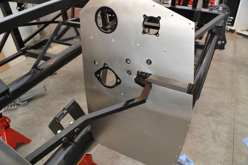
Footbox before the mod started, including the frame. Note also the steering shaft bearing plate is on the outside of the footbox.
Ready for booster and master cylinder to be installed. Frame mod done. Note the steering shaft bearing plate is now on the inside of the footbox. In this case, because the master cylinder hole was already there, only needed to extend it down a bit and drill a couple new holes for the mounting.
Booster and MC ready for installation.
Booster and MC installed on footbox. Note how close the booster is to the steering shaft and specifically the bearing plate. That's why it needs to be moved inside.
Hope this helps a little.
Build 1: Mk3 Roadster #5125. Sold 11/08/2014. Build 2: Mk4 Roadster #7750. Sold 04/10/2017. Build Thread Build 3: Mk4 Roadster 20th Anniversary #8674. Sold 09/07/2020. Build Thread and Video. Build 4: Gen 3 Type 65 Coupe #59. Gen 3 Coyote. Legal 03/04/2020. Build Thread and Video Build 5: 35 Hot Rod Truck #138. LS3 and 4L65E auto. Rcvd 01/05/2021. Legal 04/20/2023. Build Thread. Sold 11/9/2023.
Thanks Ed. Quite a lot different to the Mk4. I am guessing I will have to drill 4 holes to mount the booster, but no idea where it is best mounted. I'm not even sure how the brake pedal attaches to the power kit. I think I will ask Jeff at Whitby if he has some pics.
The Whitby kit is designed for use with a donor pedal box. The front panel you have installed is for the Wilwood box and I think I remember you asking questions that related to a Wilwood pedal setup. If this is the case you're trying to assemble components that were not intended to be used together.
Never safe to disagree with Jeff but I'll take a chance here. Whitby does list a Wilwood pedal box option on their website for this brake setup. "Now Available as a bolt in for use with the FFR supplied Wilwood pedal box. The WW kit includes a new steel brake pedal to replace the cast WW one. It slides right in and you are all set to install the rest of the kit. This all steel pedal are pivots on a bronze bushing."
Or looks like you could modify the existing pedal, although I'm personally not so sure this would be the best. Check these threads.
Sorry I couldn't be a little more helpful with my first response and pictures. You asked about the steering shaft bearing and at least I could show the before and after on that one.
Last edited by edwardb; 07-13-2015 at 06:43 AM.
Build 1: Mk3 Roadster #5125. Sold 11/08/2014. Build 2: Mk4 Roadster #7750. Sold 04/10/2017. Build Thread Build 3: Mk4 Roadster 20th Anniversary #8674. Sold 09/07/2020. Build Thread and Video. Build 4: Gen 3 Type 65 Coupe #59. Gen 3 Coyote. Legal 03/04/2020. Build Thread and Video Build 5: 35 Hot Rod Truck #138. LS3 and 4L65E auto. Rcvd 01/05/2021. Legal 04/20/2023. Build Thread. Sold 11/9/2023.
I have the power brake kit and I installed it on my MK4 after much frustration. The trick is to mock up the holes you need to make by using a material like plywood or heavy card board. So here is what I would do.
1. Mock up the outer footbox out of plywood.
2. Make the same holes as are on the foot box
3. Drill your holes for the brake kit.
4. Get a sharp hole saw slightly larger that the brake boot and lots of WD40.
5. Buy a dremel you will need it.
6. Once you get the mockup done transfer the new holes to the real foot box.
7. Make sure the rubber boot fits cleanly through the hole you made, if not it may tear.
8. Remember 2 of the 4 holes will fit. The other 2 are a slight bit from the original.
9. Mocking it up will make your job a lot easier.
Good luck
P.S. If Whitby would just provide a paper template their customers could avoid this mess. I would give you a template from mine but I really can't take the whole bloody thing apart.
I spoke to Whitby and Jeff assured me there are holes in the steel that will line up with the booster. I just need to punch them through the aluminum. He was right. I do however have to enlarge the main hole in the steel for the booster rubber boot fit through. The steel is nearly 5mm thick and not sure the best way to achieve this. A hole saw needs material at the centre to guide the blade, so can't do that idea.
I do however have to enlarge the main hole in the steel for the booster rubber boot fit through. The steel is nearly 5mm thick and not sure the best way to achieve this. A hole saw needs material at the centre to guide the blade, so can't do that idea.
I used a die grinder.
Build 1: Mk3 Roadster #5125. Sold 11/08/2014. Build 2: Mk4 Roadster #7750. Sold 04/10/2017. Build Thread Build 3: Mk4 Roadster 20th Anniversary #8674. Sold 09/07/2020. Build Thread and Video. Build 4: Gen 3 Type 65 Coupe #59. Gen 3 Coyote. Legal 03/04/2020. Build Thread and Video Build 5: 35 Hot Rod Truck #138. LS3 and 4L65E auto. Rcvd 01/05/2021. Legal 04/20/2023. Build Thread. Sold 11/9/2023.
Ed,
I am a bit of a novice with metalwork. I'm good with building guitars though!!
Anyway, a die grinder? What's that? Is there something specific you can recommend for efficient steel removal?
If FFR started building the chassis from Ash, like British Morgans, then I would be in my element!!
Ed,
I am a bit of a novice with metalwork. I'm good with building guitars though!!
Anyway, a die grinder? What's that? Is there something specific you can recommend for efficient steel removal?
If FFR started building the chassis from Ash, like British Morgans, then I would be in my element!!
I understand completely. My experience before this hobby was completely woodworking as well. A die grinder is basically a Dremel on steroids. Most commonly are air driven, although they're air hogs so you need to have a decent air supply. Both air and electric versions are available at Harbor Freight for cheap and other tool places if you want to spend a little more. The H-F variety is OK, but the stones they provide are pretty marginal IMO. I use this one: http://www.harborfreight.com/1-4-qua...der-92144.html. Just be prepared to work at it awhile. That steel plate on front of the footbox is TOUGH.
Funny you mention Morgans. I saw the special on TV the other day where they were making the Morgan Aero Super Sports. Between the woodworking and pop riveting aluminum panels, I felt right at home. Interesting car.
Last edited by edwardb; 07-14-2015 at 01:29 PM.
Build 1: Mk3 Roadster #5125. Sold 11/08/2014. Build 2: Mk4 Roadster #7750. Sold 04/10/2017. Build Thread Build 3: Mk4 Roadster 20th Anniversary #8674. Sold 09/07/2020. Build Thread and Video. Build 4: Gen 3 Type 65 Coupe #59. Gen 3 Coyote. Legal 03/04/2020. Build Thread and Video Build 5: 35 Hot Rod Truck #138. LS3 and 4L65E auto. Rcvd 01/05/2021. Legal 04/20/2023. Build Thread. Sold 11/9/2023.
Ed,
Morgans are interesting, but I don't think particularly good looking!
A guy at work who happens to be a welder, recommends using a hole saw. He said clamp a piece across the hole so the centre drill has something to drill on, then go for it. Milwaukee do some that are supposed to work on steel so may try that. Do you think this idea will be ok?
A guy at work who happens to be a welder, recommends using a hole saw. He said clamp a piece across the hole so the centre drill has something to drill on, then go for it. Milwaukee do some that are supposed to work on steel so may try that. Do you think this idea will be ok?
Sure, that could work.
Build 1: Mk3 Roadster #5125. Sold 11/08/2014. Build 2: Mk4 Roadster #7750. Sold 04/10/2017. Build Thread Build 3: Mk4 Roadster 20th Anniversary #8674. Sold 09/07/2020. Build Thread and Video. Build 4: Gen 3 Type 65 Coupe #59. Gen 3 Coyote. Legal 03/04/2020. Build Thread and Video Build 5: 35 Hot Rod Truck #138. LS3 and 4L65E auto. Rcvd 01/05/2021. Legal 04/20/2023. Build Thread. Sold 11/9/2023.
I would still go with the plywood route. Just bolt the plywood to the inside of the foot box and use that to drill with your hole saw. That way you have something to drill into so you get your hole exactly where you need it. When I did mine I made the hole large enough so it would not interfere with the rubber boot. I also spent a lot of time with my dremel to make sure the hole is as smooth as possible. I have an MK4 and am using the Wilwood pedal box. I also had to drill holes in the top mounting bracket to make sure I could tighten the top 2 nuts. Be careful with drilling these holes as I screwed it up and had to by another bracket from FFR. Good Luck.
Thanks everyone. I ended up with Milwaukee 2 3/4" dia which was perfect. Still took about 5 minutes and lots of lubrication. I just need to re-powder coat the bracket. I'll throw that in the oven tonight.
I am still trying to figure out how you adjust the pedal height. The pedal connects directly to the booster arm, and the seems no way of adjusting anything.
I know I am reviving an old thread, but were you able to adjust the pedal height? Also, a long time ago I read somewhere that adding power brakes made it so you couldn't adjust your brake bias. Is that true with this set up? (Might have been just for hydro boost brakes). Lastly, would you recommend it?
5.0 HO from a '93 Mustang, SVE heads, Trickflow stage 1 cam, Trickflow Street Burner intake manifold, T-5 w/mid shift, IRS
Delivery 9-10-16, First Start 12-28-16, First Go-Kart 2-18-17
Build thread: http://thefactoryfiveforum.com/showt...MK4-8951-Build
I know I am reviving an old thread, but were you able to adjust the pedal height? Also, a long time ago I read somewhere that adding power brakes made it so you couldn't adjust your brake bias. Is that true with this set up? (Might have been just for hydro boost brakes). Lastly, would you recommend it?
For this setup, typically the pedal height can be adjusted with spacers between the booster and the front of the pedal box. As I recall, the kit came with bushing spacers. But it's been awhile. The brake bias discussion has nothing to do with vacuum vs. hydroboost. The Wilwood pedal box, which is now quite common in these builds, has a separate master cylinder for the front and rear brakes. Front/rear bias can be adjusted using the balance bar between the two MC's. When changing to power brakes with the Wilwood pedal box, whatever the boost method, a single master cylinder is used for both front and back. Resulting in the Wilwood capability being lost. But it's still possible to adjust front/rear bias with a proportioning valve in the brake line. That used to be pretty common. The Mk3 I posted about early in this thread had one. Typically it's put on the rear circuit. But there are some that put it on the front circuit. That's a whole other discussion. Depending on your intended use of the car, the kind of brakes, pads, etc. a proportioning valve may not be required.
Build 1: Mk3 Roadster #5125. Sold 11/08/2014. Build 2: Mk4 Roadster #7750. Sold 04/10/2017. Build Thread Build 3: Mk4 Roadster 20th Anniversary #8674. Sold 09/07/2020. Build Thread and Video. Build 4: Gen 3 Type 65 Coupe #59. Gen 3 Coyote. Legal 03/04/2020. Build Thread and Video Build 5: 35 Hot Rod Truck #138. LS3 and 4L65E auto. Rcvd 01/05/2021. Legal 04/20/2023. Build Thread. Sold 11/9/2023.
For this setup, typically the pedal height can be adjusted with spacers between the booster and the front of the pedal box. As I recall, the kit came with bushing spacers. But it's been awhile. The brake bias discussion has nothing to do with vacuum vs. hydroboost. The Wilwood pedal box, which is now quite common in these builds, has a separate master cylinder for the front and rear brakes. Front/rear bias can be adjusted using the balance bar between the two MC's. When changing to power brakes with the Wilwood pedal box, whatever the boost method, a single master cylinder is used for both front and back. Resulting in the Wilwood capability being lost. But it's still possible to adjust front/rear bias with a proportioning valve in the brake line. That used to be pretty common. The Mk3 I posted about early in this thread had one. Typically it's put on the rear circuit. But there are some that put on the front circuit. That's a whole other discussion. Depending on your intended use of the car, the kind of brakes, pads, etc. may not even be required.
That is super helpful! Thanks! I will drive around in the go-kart stage with the manual brakes to see if it is something I can get used to for street duty. It is good to know that I would not lose the ability to adjust bias - especially if I am going to track the car- by going to power.
5.0 HO from a '93 Mustang, SVE heads, Trickflow stage 1 cam, Trickflow Street Burner intake manifold, T-5 w/mid shift, IRS
Delivery 9-10-16, First Start 12-28-16, First Go-Kart 2-18-17
Build thread: http://thefactoryfiveforum.com/showt...MK4-8951-Build
I installed the booster on my Mk4. To drill the hole I went the plywood/hole saw route and it worked well and fast. As I recall the bolt holes were a little off. A file or die grinder works there. You will still have to work on the bracket the pedals are hung from as the bolts holding the booster to the firewall hit it. Just make a hole around the radius of the bracket. Drill and file work here. As far as the spacer for correct pedal height, I ordered the spacer from replica parts. It's better than using the Whitby spacers as it makes a 360 degree seal around the back of the booster corrugated bellows. Problem with it is its supposed to be 3/8 inch thick. When I got it it measured 1/2 inch thick. That moved the pedal too close to the firewall. After making multiple measurements I found the ideal thickness is 5/16 inch. Fortunately I work at a place that could mill it that thickness. It's not aluminum it's a fiber compound. It works beautifully after all the work installing it. Keep at it. You'll get it done and then you can move on to another problem. Just kidding. I have thoroughly enjoyed building mine. Chassis is done and working on body fitment. You will look back on this as a very fulfilling experience. Once you get the booster in you will gain a lot of confidence in your skills. It really is surprising to me the amount of pieces we can make in these builds. Also there is a lot of help on this forum. Edwardb has been a huge help to me along with others. Good luck.
That is super helpful! Thanks! I will drive around in the go-kart stage with the manual brakes to see if it is something I can get used to for street duty. It is good to know that I would not lose the ability to adjust bias - especially if I am going to track the car- by going to power.
lahs,
You did the pedal mod for your manual brakes, right? if not you'll be like so many others who failed to do so and end up not being happy with your brakes. To clarify RE:bias; with a single master cylinder you can't truly adjust bias like you can with a dual system however you can compensate and balance by using differeing pad compounds front to rear, going to different calipers on one end or the other or by taking away braking on the strong end with the previously mentioned valve.
Forgot to ask. What reservoir are you going to use? If you have a hydraulic cluctch you'll need a triple reservoir. I purchased a cnc reservoir mounted it on a vertical bracket attached to the side of the foot box and found out later that it interfered with the engine. Money fixed that--had to buy another reservoir. Scott's hot rods has a narrower reservoir that worked perfectly. Still have the cnc if you could make it work. Make me an offer.
I installed the booster on my Mk4. To drill the hole I went the plywood/hole saw route and it worked well and fast. As I recall the bolt holes were a little off. A file or die grinder works there. You will still have to work on the bracket the pedals are hung from as the bolts holding the booster to the firewall hit it. Just make a hole around the radius of the bracket. Drill and file work here. As far as the spacer for correct pedal height, I ordered the spacer from replica parts. It's better than using the Whitby spacers as it makes a 360 degree seal around the back of the booster corrugated bellows. Problem with it is its supposed to be 3/8 inch thick. When I got it it measured 1/2 inch thick. That moved the pedal too close to the firewall. After making multiple measurements I found the ideal thickness is 5/16 inch. Fortunately I work at a place that could mill it that thickness. It's not aluminum it's a fiber compound. It works beautifully after all the work installing it. Keep at it. You'll get it done and then you can move on to another problem. Just kidding. I have thoroughly enjoyed building mine. Chassis is done and working on body fitment. You will look back on this as a very fulfilling experience. Once you get the booster in you will gain a lot of confidence in your skills. It really is surprising to me the amount of pieces we can make in these builds. Also there is a lot of help on this forum. Edwardb has been a huge help to me along with others. Good luck.
That is great info! Thanks!
5.0 HO from a '93 Mustang, SVE heads, Trickflow stage 1 cam, Trickflow Street Burner intake manifold, T-5 w/mid shift, IRS
Delivery 9-10-16, First Start 12-28-16, First Go-Kart 2-18-17
Build thread: http://thefactoryfiveforum.com/showt...MK4-8951-Build
lahs,
You did the pedal mod for your manual brakes, right? if not you'll be like so many others who failed to do so and end up not being happy with your brakes. To clarify RE:bias; with a single master cylinder you can't truly adjust bias like you can with a dual system however you can compensate and balance by using differeing pad compounds front to rear, going to different calipers on one end or the other or by taking away braking on the strong end with the previously mentioned valve.
Jeff
Hmmm pedal mod? Does that apply to the willwood pedal box?
5.0 HO from a '93 Mustang, SVE heads, Trickflow stage 1 cam, Trickflow Street Burner intake manifold, T-5 w/mid shift, IRS
Delivery 9-10-16, First Start 12-28-16, First Go-Kart 2-18-17
Build thread: http://thefactoryfiveforum.com/showt...MK4-8951-Build
Forgot to ask. What reservoir are you going to use? If you have a hydraulic cluctch you'll need a triple reservoir. I purchased a cnc reservoir mounted it on a vertical bracket attached to the side of the foot box and found out later that it interfered with the engine. Money fixed that--had to buy another reservoir. Scott's hot rods has a narrower reservoir that worked perfectly. Still have the cnc if you could make it work. Make me an offer.
That is great to know. I am definitely interested but I need to allocate my funds elsewhere at the moment. I will definitely hit you up when the time comes though.
5.0 HO from a '93 Mustang, SVE heads, Trickflow stage 1 cam, Trickflow Street Burner intake manifold, T-5 w/mid shift, IRS
Delivery 9-10-16, First Start 12-28-16, First Go-Kart 2-18-17
Build thread: http://thefactoryfiveforum.com/showt...MK4-8951-Build
Hmmm pedal mod? Does that apply to the willwood pedal box?
No. Doesn't apply to the Wilwood pedal box. They are designed to be manual brakes. Only applies to Mustang pedal boxes. Changes the pivot point.
Build 1: Mk3 Roadster #5125. Sold 11/08/2014. Build 2: Mk4 Roadster #7750. Sold 04/10/2017. Build Thread Build 3: Mk4 Roadster 20th Anniversary #8674. Sold 09/07/2020. Build Thread and Video. Build 4: Gen 3 Type 65 Coupe #59. Gen 3 Coyote. Legal 03/04/2020. Build Thread and Video Build 5: 35 Hot Rod Truck #138. LS3 and 4L65E auto. Rcvd 01/05/2021. Legal 04/20/2023. Build Thread. Sold 11/9/2023.
No. Doesn't apply to the Wilwood pedal box. They are designed to be manual brakes. Only applies to Mustang pedal boxes. Changes the pivot point.
Gotcha. Thanks for clearing that up.
5.0 HO from a '93 Mustang, SVE heads, Trickflow stage 1 cam, Trickflow Street Burner intake manifold, T-5 w/mid shift, IRS
Delivery 9-10-16, First Start 12-28-16, First Go-Kart 2-18-17
Build thread: http://thefactoryfiveforum.com/showt...MK4-8951-Build
Now Available as a bolt in for use with the FFR supplied Wilwood pedal box. The WW kit includes a new steel brake pedal to replace the cast WW one. It slides right in and you are all set to install the rest of the kit. This all steel pedal pivots on a bronze bushing. The kit for the Wilwood pedal box is $581.00.
I was on the fence about my brakes using the wilwood pedals, 13 inch Cobra brakes, and no booster during the go cart stage. I wasn't sure that the non-power brakes would work well enough. However, once I got the car on the road, the non power brakes are more than sufficient, and once used to the feel, quite easy and comfortable to use. I think this is really just a part of the build that depends on what brake pedal feel you prefer. I am glad I have power steering though.
LS1, TKO600, IRS, no scoop, undercar exhaust. Delivered June 14, 2017, First start December 31, 2017, Registered and Titled Sept 12, 2019.
I have the power brake kit and I installed it on my MK4 after much frustration. The trick is to mock up the holes you need to make by using a material like plywood or heavy card board. So here is what I would do.
1. Mock up the outer footbox out of plywood.
2. Make the same holes as are on the foot box
3. Drill your holes for the brake kit.
4. Get a sharp hole saw slightly larger that the brake boot and lots of WD40.
5. Buy a dremel you will need it.
6. Once you get the mockup done transfer the new holes to the real foot box.
7. Make sure the rubber boot fits cleanly through the hole you made, if not it may tear.
8. Remember 2 of the 4 holes will fit. The other 2 are a slight bit from the original.
9. Mocking it up will make your job a lot easier.
Good luck
P.S. If Whitby would just provide a paper template their customers could avoid this mess. I would give you a template from mine but I really can't take the whole bloody thing apart.
surprised that 5 years later, still no template!
I'll be trying this setup above... sadly I think I broke my dremel clutch when cutting the 3/4" bar to install the extendsion
I would still go with the plywood route. Just bolt the plywood to the inside of the foot box and use that to drill with your hole saw. That way you have something to drill into so you get your hole exactly where you need it. When I did mine I made the hole large enough so it would not interfere with the rubber boot. I also spent a lot of time with my dremel to make sure the hole is as smooth as possible. I have an MK4 and am using the Wilwood pedal box. I also had to drill holes in the top mounting bracket to make sure I could tighten the top 2 nuts. Be careful with drilling these holes as I screwed it up and had to by another bracket from FFR. Good Luck.
seems like the lower driver side hole lines up, ran a 3/8 drill bit thru and was minimal
the lower passenger hole is a total pain, using titanium bits and started with a 1/8 bit and have walked it up
burned a few bits in the process
I’m concerned that my hole saw is going to have a horrible time going through the steel panel and the Wilwood bracket


 Thanks:
  Likes:


 Reply With Quote


 but I'll take a chance here. Whitby does list a Wilwood pedal box option on their website for this brake setup. "Now Available as a bolt in for use with the FFR supplied Wilwood pedal box. The WW kit includes a new steel brake pedal to replace the cast WW one. It slides right in and you are all set to install the rest of the kit. This all steel pedal are pivots on a bronze bushing."


