-
01-01-2019, 11:26 PM
#161
Senior Member


Originally Posted by
PeteMeindl

We have a couple questions:
- When looking at other build threads, we don't often see a frame extension sticking towards where the driver sits where you mount the pillow block that far back (as you see in the above picture). It looks like FF drilled holes for the pillow block at the far end of the bracket. Should we move the placement of the pillow block further towards the front of the car and drill some new holes or just keep it where it is? It just seems like most of the time people mount this pillow block further forward. Either way, we'll need to add a decent sized spacer to raise the pillow block enough to keep the steering shaft off of the frame - I think this is ok, right?
- In the manual, it mentions to use threadlocker on the steering shaft but we weren't quite sure where - where do you guys use threadlocker on the steering shaft?
A year or so ago (plus or minus) Factory Five redesigned the upper steering column mount to the longer version you have. This is the best picture I could find of the old version. Zoom in and you can see it. I'd be willing to bet that many build threads you're looking at have this older version, hence the confusion.
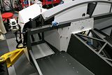
Looks like the pictures in even the newest build manual are also still the older version. Although I haven't built with it, I've seen where others have reported the steering shaft hitting exactly like what's happening with yours. Many use the Russ Thompson turn signal assembly, which he has re-designed so it works with the new mount. Using it spaces the column up so it doesn't hit. If you're not using his mount, then add a spacer on each side of the bearing high enough to not interfere with the chassis.
Probably they're talking about thread locker on the set screws on the upper and lower bearings. I wouldn't be in a hurry. You may end up with the steering shaft in and out a couple times before you're done. I always seem to.
Edit: cv2065 posted a similar explanation at the same time as me. At least we agree. 
Build 1: Mk3 Roadster #5125. Sold 11/08/2014.
Build 2: Mk4 Roadster #7750. Sold 04/10/2017.
Build Thread
Build 3: Mk4 Roadster 20th Anniversary #8674. Sold 09/07/2020.
Build Thread and
Video.
Build 4: Gen 3 Type 65 Coupe #59. Gen 3 Coyote. Legal 03/04/2020.
Build Thread and
Video
Build 5: 35 Hot Rod Truck #138. LS3 and 4L65E auto. Rcvd 01/05/2021. Legal 04/20/2023.
Build Thread. Sold 11/9/2023.
-
Post Thanks / Like - 1 Thanks, 0 Likes
-
01-02-2019, 10:55 AM
#162

Originally Posted by
edwardb
A year or so ago (plus or minus) Factory Five redesigned the upper steering column mount to the longer version you have. This is the best picture I could find of the old version. Zoom in and you can see it. I'd be willing to bet that many build threads you're looking at have this older version, hence the confusion.
Looks like the pictures in even the newest build manual are also still the older version. Although I haven't built with it, I've seen where others have reported the steering shaft hitting exactly like what's happening with yours. Many use the Russ Thompson turn signal assembly, which he has re-designed so it works with the new mount. Using it spaces the column up so it doesn't hit. If you're not using his mount, then add a spacer on each side of the bearing high enough to not interfere with the chassis.
Probably they're talking about thread locker on the set screws on the upper and lower bearings. I wouldn't be in a hurry. You may end up with the steering shaft in and out a couple times before you're done. I always seem to.
Edit: cv2065 posted a similar explanation at the same time as me. At least we agree.
Thanks, Paul! Yeah, that all makes sense and we'll take that path. One other interesting change that seems to have happened is that the accelerator bracket has changed such that the steering shaft now goes between the 2 accelerator attachment points on the left of the pedal assembly (the shaft now passes just under the top attachment point) rather than above both attachment points which is I think how it was in the past.
Happy new year to you and thank you for all of your help!
-
01-05-2019, 10:02 PM
#163
-
01-06-2019, 12:11 AM
#164
Looking good.
Regarding the foot box and rivets, I’d try to just rivet the panels together. If you need to run some into the 2” tube it’s not a problem. I didn’t rivet into the main tubes for the floors but many do from what I have seen.
I’d postpone riveting panels together until you can’t go any further. It’s nice to be able to take it apart if you have to get to something. When the panels are loose you can reach through the frame. Once the rivets are in you are going under and over. That’s when I understood why lifts were so popular.
-Steve
-
Post Thanks / Like - 1 Thanks, 0 Likes
-
01-06-2019, 07:55 AM
#165
Senior Member
Agree with Steve's comments. Couple more. See from your pics your panels are all still raw, including the ink marking. Are you planning to finish them in some way? Paint, powder coat, Sharkhide, whatever? If so, you want to do that after drilling and fitting, but before permanently mounting them. Also, I'd recommend after drilling that you take the time to clean up the drilled holes. I see a lot of burrs and flash around your holes. That's going to get in the way of setting the rivets properly and just generally needs to be cleaned up before whatever finish you do. You can use a deburring tool, a countersink bit, or I use a large nice sharp 5/8-inch drill bit and just twist it in the hole by hand. Cleans them right up.
Build 1: Mk3 Roadster #5125. Sold 11/08/2014.
Build 2: Mk4 Roadster #7750. Sold 04/10/2017.
Build Thread
Build 3: Mk4 Roadster 20th Anniversary #8674. Sold 09/07/2020.
Build Thread and
Video.
Build 4: Gen 3 Type 65 Coupe #59. Gen 3 Coyote. Legal 03/04/2020.
Build Thread and
Video
Build 5: 35 Hot Rod Truck #138. LS3 and 4L65E auto. Rcvd 01/05/2021. Legal 04/20/2023.
Build Thread. Sold 11/9/2023.
-
Post Thanks / Like - 1 Thanks, 0 Likes
-
01-06-2019, 09:07 AM
#166
Senior Member

Don't know if you have compressed air available, but a pnuematic riveter will fast become your new best friend.
John D. - Minneapolis 'Burbs
1965 El Camino - LT-1, 4L60e, 4wh discs, SC&C susp.
2013 F-150 Platinum - Twin Turbo 3.5
2018 Mk4 Roadster w/ Coyote - #9365 - Build Thread Delivery 7/3/18, 1st Start 1/4/19, 1st Road Mile 5/5/19, Legal 6/18/19, In Paint 2/25/21, Done (?) 4/2021
-
01-06-2019, 09:30 AM
#167
Not a waxer

Originally Posted by
edwardb
...See from your pics your panels are all still raw, including the ink marking. Are you planning to finish them in some way? Paint, powder coat, Sharkhide, whatever? If so, you want to do that after drilling and fitting, but before permanently mounting them...
Just adding to Paul's comment...if you intend to leave them raw as many do take acetone or lacquer thinner and remove the ink markings ASAP. A thin layer of oxidation begins to build on the surface as soon as the aluminum sheets are manufactured but will not occur (at least not to the same level) over the ink---if you wait to clean the ink off the layer will be even heavier on the non-inked area and although the black markings will be gone you'll still see the less oxidized "shadow" of where it was.
Jeff
-
Post Thanks / Like - 1 Thanks, 0 Likes
-
01-06-2019, 09:38 AM
#168
Thanks, Straversi! Sounds good - I'll go that route.
-
01-06-2019, 09:44 AM
#169
Originally Posted by
edwardb
Agree with Steve's comments. Couple more. See from your pics your panels are all still raw, including the ink marking. Are you planning to finish them in some way? Paint, powder coat, Sharkhide, whatever? If so, you want to do that after drilling and fitting, but before permanently mounting them. Also, I'd recommend after drilling that you take the time to clean up the drilled holes. I see a lot of burrs and flash around your holes. That's going to get in the way of setting the rivets properly and just generally needs to be cleaned up before whatever finish you do. You can use a deburring tool, a countersink bit, or I use a large nice sharp 5/8-inch drill bit and just twist it in the hole by hand. Cleans them right up.
Thanks, Paul! What we've done so far before permanently mounting the panels (for the few that we've riveted) has been to acetone them to get rid of the markings and then sharkhiding them. We'll do that with these panels too before we mount them for good. Thanks for the good idea around deburring the holes - i like your 5/8 drill bit idea, nice and simple and gets the job done! We'll do that to clean it up!
-
01-06-2019, 09:46 AM
#170
Originally Posted by
Jeff Kleiner
Just adding to Paul's comment...if you intend to leave them raw as many do take acetone or lacquer thinner and remove the ink markings ASAP. A thin layer of oxidation begins to build on the surface as soon as the aluminum sheets are manufactured but will not occur (at least not to the same level) over the ink---if you wait to clean the ink off the layer will be even heavier on the non-inked area and although the black markings will be gone you'll still see the less oxidized "shadow" of where it was.
Jeff
Thanks, Jeff! I've noticed that shadow on the previous panels we've acetoned and sharkhided and didn't realize what the cause was - now I do. Thanks a lot!
-
01-10-2019, 10:45 PM
#171
-
01-11-2019, 07:19 AM
#172
Senior Member
For those bent floor pieces that are extending above the top of the transmission tunnel, no you don't want that extra material there. It will prevent the transmission tunnel cover top from mounting properly against the chassis tubes. Looks like you already have it drilled and cleco'd. I've noticed they may extend slightly and need a little trimming. But not that much. I've found you need to push the corner down at the floor level pretty firmly to get them to go down all or most of the way. Maybe try that and see if they'll go down more. Otherwise, I'd trim them. But as a last resort. My usual advice regarding the aluminum panels is they're well proven and precisely laser cut. If something doesn't fit right, check the assembly, proper overlap, etc. before cutting metal. Almost always not required. My main experience with occasional trimming (just a little...) is to clear welds so they sit flat.
Build 1: Mk3 Roadster #5125. Sold 11/08/2014.
Build 2: Mk4 Roadster #7750. Sold 04/10/2017.
Build Thread
Build 3: Mk4 Roadster 20th Anniversary #8674. Sold 09/07/2020.
Build Thread and
Video.
Build 4: Gen 3 Type 65 Coupe #59. Gen 3 Coyote. Legal 03/04/2020.
Build Thread and
Video
Build 5: 35 Hot Rod Truck #138. LS3 and 4L65E auto. Rcvd 01/05/2021. Legal 04/20/2023.
Build Thread. Sold 11/9/2023.
-
Post Thanks / Like - 1 Thanks, 0 Likes
-
01-12-2019, 02:59 PM
#173
Originally Posted by
edwardb
For those bent floor pieces that are extending above the top of the transmission tunnel, no you don't want that extra material there. It will prevent the transmission tunnel cover top from mounting properly against the chassis tubes. Looks like you already have it drilled and cleco'd. I've noticed they may extend slightly and need a little trimming. But not that much. I've found you need to push the corner down at the floor level pretty firmly to get them to go down all or most of the way. Maybe try that and see if they'll go down more. Otherwise, I'd trim them. But as a last resort. My usual advice regarding the aluminum panels is they're well proven and precisely laser cut. If something doesn't fit right, check the assembly, proper overlap, etc. before cutting metal. Almost always not required. My main experience with occasional trimming (just a little...) is to clear welds so they sit flat.
Thanks, Paul! We will try to push that panel down further and see if we can get it to line up. What you said makes a lot of sense.
Anyone have any thoughts on the drill bits for widening out those fuel intakes? Maybe it's not too big a deal what size you use?
Thanks, guys - hope you all are having a good weekend!
-
01-19-2019, 08:44 PM
#174
Fuel Tank and Rear Brake Install
Hey guys, Pete's son Jamie here. We've been working on the installing the rear brakes and the fuel tank and have run into a couple of issues. For the rear brakes, it seems that part of the brake caliper is rubbing on the rotor. Could putting in the brake fluid fix this issue? Also with the rear brakes, the supplied bolts seem to be too long and if fully tightened would come close to hitting the rotor. Is this normal or should we use different hardware? Any advice would be greatly appreciated.
I know it's hard to see in this picture, but the part is not the only thing touching the rotor. Also, the mounting hardware is not fully tightened and would come close to the rotor if it was.

This is the part of the caliper that is hitting the rotor.

Next, we began work on the fuel tank and finished installing the fuel level sender, pickup, and filler tube. However, while trying to put it onto the chassis, we could not get the straps to fit around and attach onto the hardware. On both sides, we are close to attaching it but cannot quite get there.
Driver side strap:

Passenger side strap:

Has anyone else had a similar issue? We were thinking that we get some longer bolts to attach it but wanted to see if anyone had a different idea. Again, thanks so much for all the help we have received. Hope everyone has a great weekend.
-
01-19-2019, 10:28 PM
#175
I'll address the fuel tank straps... It's not uncommon for the bolts provided to be just barely long enough... I would suggest swapping them out with some longer stainless steel ones. Those original ones will rust pretty quickly anyway.
Also, just an observation, I see the chrome rear end cover. Many people believe that the chrome covers traps a lot of heat internally. They would also suggest putting on a cast aluminum cover to help with that heat. I'm sure that there is some merit to this, but under normal street driving, I'm not sure it is a big issue. Just an observation.
Last edited by BadAsp427; 01-19-2019 at 10:31 PM.
-
Post Thanks / Like - 1 Thanks, 0 Likes
-
01-19-2019, 10:50 PM
#176
Senior Member
I see lots of comments on multiple threads about using stainless hardware. I use my share too... But two words of caution just in case. (1) The normal hardware store variety SS hardware isn't particularly strong. Likely not even as strong as average steel grade 5 hardware. Often not an issue, but just be aware. There's specialty stuff out there that's much stronger at places like Fastenal, McMaster, etc. But it's not cheap. (2) Get in the habit of using a dab of anti-seize lubricant when assembling with SS hardware. It has a bad habit of occasionally galling and then locking in place. At that point nearly impossible to get apart without destroying something. Usually at the worst possible moment. Ask me how I know.
Build 1: Mk3 Roadster #5125. Sold 11/08/2014.
Build 2: Mk4 Roadster #7750. Sold 04/10/2017.
Build Thread
Build 3: Mk4 Roadster 20th Anniversary #8674. Sold 09/07/2020.
Build Thread and
Video.
Build 4: Gen 3 Type 65 Coupe #59. Gen 3 Coyote. Legal 03/04/2020.
Build Thread and
Video
Build 5: 35 Hot Rod Truck #138. LS3 and 4L65E auto. Rcvd 01/05/2021. Legal 04/20/2023.
Build Thread. Sold 11/9/2023.
-
Post Thanks / Like - 1 Thanks, 0 Likes
-
01-20-2019, 07:36 AM
#177
Senior Member
Can't comment on the brake caliper interference...
Gas Tank:
As stated the bolts are just barely long enough to catch the nut - if at all. I replaced mine with standard grade 5 zinc coated hex bolts. (What is this affinity for socket head Allen bolts??)
I went with either 1/4 or 1/2 inch longer (whatever was available). Trying to get an Allen wrench into the socket after a few months of road crud isn't fun.
Don't bother with stainless. Nobody's gonna see it, they're not strong, and the 54 year old raw steel bolts on my El Camino's tank straps haven't rusted away yet - and it spent the 1st four decades of it's life as a daily.
John D. - Minneapolis 'Burbs
1965 El Camino - LT-1, 4L60e, 4wh discs, SC&C susp.
2013 F-150 Platinum - Twin Turbo 3.5
2018 Mk4 Roadster w/ Coyote - #9365 - Build Thread Delivery 7/3/18, 1st Start 1/4/19, 1st Road Mile 5/5/19, Legal 6/18/19, In Paint 2/25/21, Done (?) 4/2021
-
Post Thanks / Like - 1 Thanks, 0 Likes
-
01-20-2019, 09:30 PM
#178
Thanks, BadAsp, Paul, and John! We will get some longer bolts and that should solve our fuel tank issue. Looking forward to getting that installed!
-
01-20-2019, 09:40 PM
#179
Potential solution for rear brake issue
We are hoping we may have come up with a solution to our rear brake issue. As we mentioned, right now when we put the bolts in to connect the rear brakes to the bracket on the rear axle, the bolts are just a bit too long (maybe a mm or two) and they can come in contact with the rotors (as well as a center part of the brake itself, mentioned in a previous post). See in the picture below:
Our potential solution is to put some washers in between the two brackets from the axle, pushing the upper bracket plate in the picture above to the left and thus moving the brake to the left a mm or 2 and that, i hope, will keep the rotor from coming in contact with the bolts and center part of the brake. I think that will help out - let me know if you think this is a bad idea. Thanks, guys!
-
01-21-2019, 06:18 AM
#180
Senior Member
Don't know if this will work or not (without parts in hand/looking at it), but it costs nothing but a little time...
I played around with your pic on a photoediting program and moved the parts around, and this may solve your problem. (I didn't save the "moving around" pic, but the overlay setup of the new configuration seemed to solve your problem). And now that I think about it, I think had to do this when I put discs on the rear of my El Camino.
Now if this idea will require serious trimming/grinding/modifying the brackets don't do it. If it's just a little shave to clear a weld bead or something it's your call... but just jigging this up may reveal it's the solution.
Flip the orientation of the brackets. Move the axle flange bracket to the inboard/inside surface of the axle flange, and mount the caliper/caliper bracket to the outboard/outside surface of the axle flange bracket. They'll still be in the same plane, but I think you'll gain that 1/16" clearance your looking for.
rearBrake2e.jpg
John D. - Minneapolis 'Burbs
1965 El Camino - LT-1, 4L60e, 4wh discs, SC&C susp.
2013 F-150 Platinum - Twin Turbo 3.5
2018 Mk4 Roadster w/ Coyote - #9365 - Build Thread Delivery 7/3/18, 1st Start 1/4/19, 1st Road Mile 5/5/19, Legal 6/18/19, In Paint 2/25/21, Done (?) 4/2021
-
Post Thanks / Like - 1 Thanks, 0 Likes
-
01-21-2019, 03:41 PM
#181
Originally Posted by
Fixit
Don't know if this will work or not (without parts in hand/looking at it), but it costs nothing but a little time...
I played around with your pic on a photoediting program and moved the parts around, and this may solve your problem. (I didn't save the "moving around" pic, but the overlay setup of the new configuration seemed to solve your problem). And now that I think about it, I think had to do this when I put discs on the rear of my El Camino.
Now if this idea will require serious trimming/grinding/modifying the brackets don't do it. If it's just a little shave to clear a weld bead or something it's your call... but just jigging this up may reveal it's the solution.
Flip the orientation of the brackets. Move the axle flange bracket to the inboard/inside surface of the axle flange, and mount the caliper/caliper bracket to the outboard/outside surface of the axle flange bracket. They'll still be in the same plane, but I think you'll gain that 1/16" clearance your looking for.
rearBrake2e.jpg
Ha - good thinking, John! I have to say I'm very grateful that you took the time to play around with this in a photo-editor to try to solve my problem - you go above and beyond the call of duty! Thank you.
-
01-26-2019, 06:55 PM
#182
Installing the fuel tank
Today we got some longer bolts for the fuel tank straps and installed the fuel tank. We then got the fuel filter and riveted that to the frame and connected it to the feul tank. Here are a couple shots:
The entire tank:

Looking at the connection to the fuel filter:

We also put in Jeff Kleiner's quick jack mod - great idea Jeff! Thanks.
Now on to the fuel lines!
-
01-26-2019, 07:12 PM
#183
Thinking about fuel lines
We've been mapping out where to run the fuel lines and wanted to see what you guys thought of our plan. First off, we have 2 segments of fuel line (each 5 ft). We don't have a flaring tool thus I think we either have to use 5 ft or a full 10 ft of line. From laying things out, it seems like we could use just one 5 ft segment and run the line starting just above the main 4 inch chassis tube in the rear, run it towards the front along the outside of the chassis tube, and then curve it up to the engine bay. This means we'd use the nylon hose provide to run from the fuel filter in the rear, rivet it into the frame along the vertical arm coming out above the 4 inch tube at the rear of the car, and meeting the hard line where the red circle is below.

We'd basically do the same route for both the in and out bound lines.
Does that seem reasonable to you guys? Thanks for any thoughts!
-
Post Thanks / Like - 0 Thanks, 1 Likes
-
01-27-2019, 11:15 AM
#184
It's all looking good... Question, where is your fuel pump going to be?
-
Post Thanks / Like - 1 Thanks, 0 Likes
-
01-27-2019, 09:24 PM
#185
Originally Posted by
BadAsp427
It's all looking good... Question, where is your fuel pump going to be?
Ha - great question, BadAsp! You really helped us out here - we had inserted the fuel pick-up that came with the ff kit - and totally didn't realize that a separate fuel pickup (this one with an in-tank fuel pump) was also packed up with our coyote kit! Your question prompted us to realize this!! So thank you! Time to go replace that pickup.
We have a fuel pump question we'll post in a minute...
Thanks, again!
-
01-27-2019, 09:31 PM
#186
fuel pick up question
Thanks again, BadAsp, for asking about the fuel pump. We're now trying to put together the in-tank fuel pump and it looks like we need to do some crimping. Here's a picture of the order i think these parts come together:

So i think we should strip those wires and connect them with a crimper. I've read that for automotive purposes, we might want to use a special crimping tool as a regular one isn't adequate. Is this true? Or does a regular crimper work.
If we need a special crimping tool, does anyone have a recommendation for a good tool?
Thanks!
-
01-27-2019, 10:24 PM
#187
Pete,
When these things are assembled, the wire lengths are pretty short. Is there any way to just re-pin that connector that plugs into the pump? Or better yet, with the wires attached to the hanger plug directly to the pump with the connectors that are already crimped to them? That way you wouldn't need to crimp anything and the wire lengths would be no longer than you actually need. Just a thought.
As for a crimper recommendation, here is what I have: https://www.amazon.com/gp/product/B0...?ie=UTF8&psc=1
It works great and can do several different types of connectors.
Dave
Last edited by Papa; 01-27-2019 at 10:52 PM.
-
Post Thanks / Like - 1 Thanks, 0 Likes
-
01-28-2019, 02:21 PM
#188
So cool to have the body in the living room! What a gal! You better keep her! Good luck with your build - sounds like you are off to a great start.
Craig
10/2018 -- acquired Mk3.1 #6602 which was an unfinished project in go-kart stage; 9/2019 -- completed car enough to drive locally and compete in autocross events; still in original black gel-coat; 347 Stroker w/ Holley 650 carb, roller cam; Tremec 3550; 3.51 rear diff; lots of Breeze pieces; 2021 -- XP Champion in Central PA Region - SCCA Autocross Series; 2022 - installed windshield and registered in PA; my Build Thread -- https://thefactoryfiveforum.com/show...ished-Business
6/2022 -- acquired Mk3 #1004; finished build; 347 stroker w/ Holley 560 carb SOLD
-
Post Thanks / Like - 1 Thanks, 0 Likes
-
01-28-2019, 03:29 PM
#189
Pete - If you're using the F5-supplied fuel lines, be aware that you can get compatible pre-made lines in a variety of lengths from most auto parts stores. I used one of the long ones from F5, but then a shorter version from Action Auto Parts to get the overall length I wanted. They're pre-flared with fittings. just check the flared ends before you pay for them - I found a couple with damage that probably wouldn't have sealed well.
Mk4 #8861 Complete kit. Delivered: 27 Apr 2016, currently a roller.
Gen-2 Coyote, clutch, TKO600, midshift, and solid axle from Forte. Many pieces from Breeze and Replicarparts.
-
Post Thanks / Like - 1 Thanks, 0 Likes
-
01-28-2019, 07:58 PM
#190
Originally Posted by
Papa
Pete,
When these things are assembled, the wire lengths are pretty short. Is there any way to just re-pin that connector that plugs into the pump? Or better yet, with the wires attached to the hanger plug directly to the pump with the connectors that are already crimped to them? That way you wouldn't need to crimp anything and the wire lengths would be no longer than you actually need. Just a thought.
As for a crimper recommendation, here is what I have:
https://www.amazon.com/gp/product/B0...?ie=UTF8&psc=1
It works great and can do several different types of connectors.
Dave
Thanks, Dave! That's a good idea - I'll see if i can do that.
-
01-28-2019, 08:45 PM
#191
Originally Posted by
initiator
Pete - If you're using the F5-supplied fuel lines, be aware that you can get compatible pre-made lines in a variety of lengths from most auto parts stores. I used one of the long ones from F5, but then a shorter version from Action Auto Parts to get the overall length I wanted. They're pre-flared with fittings. just check the flared ends before you pay for them - I found a couple with damage that probably wouldn't have sealed well.
Good point, Initiator. Yeah, getting some shorter lines could help me out and avoid the decision of whether to add a whole 5 ft section or not. I'll be sure to check the flared ends too. Thanks for the advice!
-
02-02-2019, 06:46 PM
#192
-
02-04-2019, 11:39 AM
#193
Originally Posted by
PeteMeindl
Then we bent our first line - It worked great and in our excitement, we realized we forgot to do what we just reminded ourselves to do.... I guess now we have a fuel line to practice on!

We've all done that
Originally Posted by
PeteMeindl
Then we taped the fixtures to the ends of the lines so we wouldn't forget again...
Good Solution
Originally Posted by
PeteMeindl
Question 1:
When using those rubber insulated clips to attach the fuel line to the chassis, we just don't seem to be able to get the two ends of clips to lie flush with the chassis - we're thinking maybe these clips work better for the 1/4 inch line and we might buy some slightly bigger ones for the 5/16 inch line. Has anyone else had this issue and come up with a good resolution?
I ordered these clamps for my 5/16" steel fuel lines. I used a 3/16" rivet to hold in place too. I probably have some left you can have.
Originally Posted by
PeteMeindl
but the exposed connection being submerged in fuel makes me feel a little worried.
ME TOO. I don't recall any wires exposed like that in my stock fuel pump assy.
Last edited by DadofThree; 02-04-2019 at 11:44 AM.
Dave
Mk 3.1 - #6882 - 5.0L 302 - FiTech EFI - 3-Link - 3.08 Ratio - 15" Wheels
Greenhorn and doing the best I can
My photos are at:
My Flickr acct
Videos are at:
YouTube Videos
-
Post Thanks / Like - 1 Thanks, 0 Likes
-
02-04-2019, 03:37 PM
#194
Originally Posted by
DadofThree
We've all done that
Too right. Usually only once, though.
I also wasn't happy with the provided clips and found some insulated stainless ones - probably exactly the same ones as Dave but from Summit Racing.
Mk4 #8861 Complete kit. Delivered: 27 Apr 2016, currently a roller.
Gen-2 Coyote, clutch, TKO600, midshift, and solid axle from Forte. Many pieces from Breeze and Replicarparts.
-
Post Thanks / Like - 1 Thanks, 0 Likes
-
02-04-2019, 04:35 PM
#195
Senior Member
Originally Posted by
PeteMeindl
Question 2:
We got the fuel pump wires connected to the wires on the fuel pickup and we were thinking of putting some heat shrink around the connection. I'm completely naive but the exposed connection being submerged in fuel makes me feel a little worried. I also like the heat shrink idea as it'll help make sure these connections don't ever come undone. Here's a pic of the connection:

So the questions are: 1) is putting heat shrink on just a silly, totally unnecessary thing to do? 2) if it's not a bad idea, is just regular heat shrink ok, or will the fuel corrode it away? and 3) if we should get special heat shrink, does anyone have a kind they like? We thought Raychem DR-25 would do the trick, but then we talked to someone at an autoparts store who said that wouldn't work in a fuel tank and that viton heat shrink was the way to go. Not easy to find that either. Any thoughts, guys? Thank you! Hope you're all doing well.
Yes, I think it's a good idea to put heat shrink around that connection. To seal it up, protect it, and make sure it doesn't come apart. Not a place you want to be having problems. But you can't use typical off-the-shelf heat shrink. Nylon or olefin are the most common, and it won't stand up to gasoline. Put some in a jar of gasoline overnight and see what happens. I'm not familiar with Raychem DR-25. When I researched this, I ended up using Molex Perma-Seal connectors. The Molex literature specifically lists gasoline as one of the chemicals it's resistant to. Related to this, I'm not sure I'd use those kind of AMP 1/4-inch blade style connectors. I recall they're rated at 15 amps, depending of course on the wire they're attached to. Your fuel pump will probably be one of your higher current draws. Plus the plastic on those crimping versions probably isn't rated to be in gasoline. I'd recommend a butt type connector like you pictured previously. Which leads me to recommending Molex Perma-Seal butt connectors. They're pretty widely available. I got mine from DelCity.net. A good source for electrical stuff in general in case you haven't discovered it yet. These if your wires are the same size: https://www.delcity.net/store/Perma!...12022.h_812023. These if they're different and you need a step-down connector (what I used): https://www.delcity.net/store/Perma!...12028.h_812029. Others may have other suggestions based on their experience. But bottom line you need something specifically made to be immersed in gasoline.
Last edited by edwardb; 02-04-2019 at 04:38 PM.
Build 1: Mk3 Roadster #5125. Sold 11/08/2014.
Build 2: Mk4 Roadster #7750. Sold 04/10/2017.
Build Thread
Build 3: Mk4 Roadster 20th Anniversary #8674. Sold 09/07/2020.
Build Thread and
Video.
Build 4: Gen 3 Type 65 Coupe #59. Gen 3 Coyote. Legal 03/04/2020.
Build Thread and
Video
Build 5: 35 Hot Rod Truck #138. LS3 and 4L65E auto. Rcvd 01/05/2021. Legal 04/20/2023.
Build Thread. Sold 11/9/2023.
-
Post Thanks / Like - 1 Thanks, 0 Likes
-
02-04-2019, 09:24 PM
#196
Originally Posted by
DadofThree
We've all done that
Good Solution
I ordered
these clamps for my 5/16" steel fuel lines. I used a 3/16" rivet to hold in place too. I probably have some left you can have.
ME TOO. I don't recall any wires exposed like that in my stock fuel pump assy.
Thanks, Dave! Very kind of you to offer up some of your clamps - i bought some yesterday just like yours actually so i think we're good to go. Thanks!
-
02-04-2019, 09:30 PM
#197
Originally Posted by
edwardb
Yes, I think it's a good idea to put heat shrink around that connection. To seal it up, protect it, and make sure it doesn't come apart. Not a place you want to be having problems. But you can't use typical off-the-shelf heat shrink. Nylon or olefin are the most common, and it won't stand up to gasoline. Put some in a jar of gasoline overnight and see what happens. I'm not familiar with Raychem DR-25. When I researched this, I ended up using Molex Perma-Seal connectors. The Molex literature specifically lists gasoline as one of the chemicals it's resistant to. Related to this, I'm not sure I'd use those kind of AMP 1/4-inch blade style connectors. I recall they're rated at 15 amps, depending of course on the wire they're attached to. Your fuel pump will probably be one of your higher current draws. Plus the plastic on those crimping versions probably isn't rated to be in gasoline. I'd recommend a butt type connector like you pictured previously. Which leads me to recommending Molex Perma-Seal butt connectors. They're pretty widely available. I got mine from DelCity.net. A good source for electrical stuff in general in case you haven't discovered it yet. These if your wires are the same size:
https://www.delcity.net/store/Perma!...12022.h_812023. These if they're different and you need a step-down connector (what I used):
https://www.delcity.net/store/Perma!...12028.h_812029. Others may have other suggestions based on their experience. But bottom line you need something specifically made to be immersed in gasoline.
Thanks a lot, Paul! That's really helpful - we'll look at getting some of those connecters and make sure that we have versions of everything that can be immersed in gasoline. This is great.
-
02-11-2019, 10:10 PM
#198
-
Post Thanks / Like - 0 Thanks, 1 Likes
-
02-11-2019, 10:20 PM
#199
Loookng good! You’ve gotten a lot accomplished!
-
Post Thanks / Like - 1 Thanks, 0 Likes
-
02-12-2019, 08:17 PM
#200
Do you have your wheels and tires yet? I had to mess with the front brake flex lines in order to avoid rubbing the tire when the wheels turn side-to-side. Eventually went with a 90-degree fitting (pointed down) right at the chassis end of each line that solved it. That trick came from this forum.
Mk4 #8861 Complete kit. Delivered: 27 Apr 2016, currently a roller.
Gen-2 Coyote, clutch, TKO600, midshift, and solid axle from Forte. Many pieces from Breeze and Replicarparts.


 Thanks:
  Likes:


 Reply With Quote


