-
Senior Member

Unfortunately, you missed the part in the manual and in other posts about flattening the flange on the fuel tank where those plastic bumpers on the frame contact the fuel tank. Those need to be against the flat of the tank flange. Not against the edge like showing in your picture. You need to correct that to get a much more solid fuel tank mounting. The provided bolts are a bit short and many replace them as you did. But leaving the flange bent like that made the situation worse.
Build 1: Mk3 Roadster #5125. Sold 11/08/2014.
Build 2: Mk4 Roadster #7750. Sold 04/10/2017.
Build Thread
Build 3: Mk4 Roadster 20th Anniversary #8674. Sold 09/07/2020.
Build Thread and
Video.
Build 4: Gen 3 Type 65 Coupe #59. Gen 3 Coyote. Legal 03/04/2020.
Build Thread and
Video
Build 5: 35 Hot Rod Truck #138. LS3 and 4L65E auto. Rcvd 01/05/2021. Legal 04/20/2023.
Build Thread. Sold 11/9/2023.
-
Post Thanks / Like - 1 Thanks, 1 Likes
-
Senior Member


Originally Posted by
edwardb

Unfortunately, you missed the part in the manual and in other posts about flattening the flange on the fuel tank where those plastic bumpers on the frame contact the fuel tank. Those need to be against the flat of the tank flange. Not against the edge like showing in your picture. You need to correct that to get a much more solid fuel tank mounting. The provided bolts are a bit short and many replace them as you did. But leaving the flange bent like that made the situation worse.
Went back and checked the manual closely and I did indeed miss that little bit of important text. I saw the flanges on the tank bent and I thought the previous builder made those bends intentionally since they were directly where the straps come up from below. This is exactly why I love keeping a detailed build thread with lots of pictures. I'll lower the tank, flatten those flanges and see how the fit looks after that. Thanks for reviewing and helping out the newbs like me!
Darryl [dbo_texas]
MKIV #9644 (build thread) (Index)
MK4 Complete Kit | Gen2 crate Coyote | Tremec T56, 3.55 IRS | power steering | hydroboost | dual roll bars | FFR carbon fiber dash | 18" Halibrands + Wilwoods | RT drop trunk kit & turn signal | front battery mount | saddle leather Intatrim Stoneleigh seats + interior accents
-
Senior Member

-
Post Thanks / Like - 0 Thanks, 1 Likes
-
Senior Member

Hi Darryl. I enjoyed getting caught up on your build thread. I remember reading back when you bought the kit, and thought it was pretty cool it also came with some good tools. It looks like you are putting together a quality build, and you're doing a great job documenting it. Keep up the good work, and thanks for sharing.
I added your NRG QR update to my quick release bookmarks. I'm going to tackle this mod in the not so distant future. Thanks again.
Chris
Coupe complete kit delivered: 4/22/24.
Build Thread. Coyote. T-56. IRS w/3.55. Wilwoods. PS. HVAC. Side windows.
MK4 Complete kit.
Build Thread Index. Delivered: 10/15/2020. Legal: 7/25/23. Coyote Gen3. TKO600 (0.64 OD). IRS w/3.55. PS. Wilwoods. Sway bars. This build is dedicated to my son, Benjamin.
Build Thread.
-
Post Thanks / Like - 0 Thanks, 1 Likes
-
Senior Member

-
Senior Member

Nice work, Darryl! I built a very similar vapor filter (also inspired by Edwardb's), and can report no fumes in the garage over the summer. It does the job. If I put my nose right at the output of the filter, I can smell gas, but even a couple feet away and no smell. I probably should have anchored my bracket in the trunk's side wall like you. Would have been easier than drilling/tapping into the 3" chassis square tube just below.
Chris
Coupe complete kit delivered: 4/22/24.
Build Thread. Coyote. T-56. IRS w/3.55. Wilwoods. PS. HVAC. Side windows.
MK4 Complete kit.
Build Thread Index. Delivered: 10/15/2020. Legal: 7/25/23. Coyote Gen3. TKO600 (0.64 OD). IRS w/3.55. PS. Wilwoods. Sway bars. This build is dedicated to my son, Benjamin.
Build Thread.
-
Post Thanks / Like - 0 Thanks, 1 Likes
-
Just curious if the carbon needs to be replaced from time to time?? Thanks,
#10333 Complete Kit, Carbed 427w, TKX, IRS and many other upgrades
- Order Date: September 11, 2021 - 20th Anniversary of 9/11
- Delivery Day: April 1, 2022 - April Fool's Day
- First Start and Go-Kart: January 20th, 2023
- Graduation Date: July 4th, 2023 - Independence Day!!
- Legal Registration Date: October 4, 2023 - My Birthday!!
Visit my MKIV Build Thread (#10333)
-
Senior Member


Originally Posted by
Ted G

Just curious if the carbon needs to be replaced from time to time?? Thanks,
Typically I think over time the carbon will become less effective and would need to be replaced. I have no idea how often that is though...I would guess maybe every year or two. I should be able to unscrew the bracket from below pull it off the vent line, pop the top cap off and re-fill. I need to see if the bracket I have will work for that or if I need to fab up something different and use the ratchet style pipe clamp (like used on hoses/barb connections). That typically requires a single screw and you just loosen it enough to wiggle the PVC out. But not sure yet...I'll need to see what access looks like with the body on.
Darryl [dbo_texas]
MKIV #9644 (build thread) (Index)
MK4 Complete Kit | Gen2 crate Coyote | Tremec T56, 3.55 IRS | power steering | hydroboost | dual roll bars | FFR carbon fiber dash | 18" Halibrands + Wilwoods | RT drop trunk kit & turn signal | front battery mount | saddle leather Intatrim Stoneleigh seats + interior accents
-
Post Thanks / Like - 1 Thanks, 1 Likes
 Ted G
Ted G thanked for this post
-
Senior Member

Carbon Fiber Dash Gauge Install
A few weekends ago I finally cut holes in the FFR carbon fiber dash so I could mount the Vintage GPS gauges. I was a bit nervous because once you start cutting you are basically locked in on gauge position. In the end, like many things related to this build, just taking time and planning ahead made the task very simple. Here are the general steps I took:
Step 1 - layout the gauges: I positioned them where I think I would have best visibility and per my aesthetic tastes. I had the seat temporarily positioned so I could evaluate visibility. I had painters tape on the dash to protect it while working.

Step 2 - I drilled a small pilot hole at the center point of each of the 7 gauges, then used a compass (old school) to trace out the diameter for each cut

Step 3 - This is when I realized some of the gauges were too close to the curved dash hoop on the frame and would interfere. So I used that pilot hole to draw the diameter of each gauge nut on the backside of the dash. I saw a couple that would have interfered, so I shifted my pilot hole down just a tad and redrew the new cutout hole diameters. Measure twice, cut once and all that...

Step 4 - To cut the actual holes, I didn't have a hole saw so I used a Dremel with a cutoff wheel to make polygon cuts for each hole. The cutoff wheel goes through the CF dash like a hot knife through butter. Just make sure to wear good PPE (long sleeve shirt, respirator, goggles) - you do NOT want that CF dust getting on your skin or in your lungs

Step 5 - After cutting the rough shape of the holes, I used a Dremel sanding drum to clean up each cut. This also worked great and the sanding drums actually remove the CF material better than I thought they would.
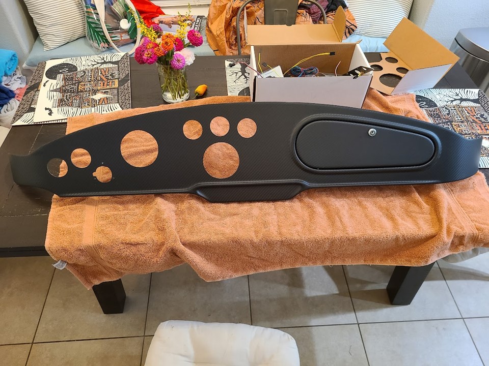
Step 6 - Finally, I was ready to mount the gauges.

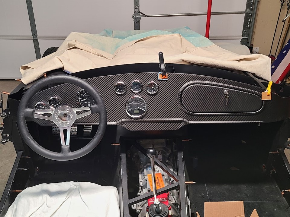
As I'm still undecided on my final color scheme, I am considering replacing the chrome bezels on the gauges with black anodized aluminum bezels which can be purchased from Speedhut. I also need to finish mounting some of the other dash items such as the indicator lights, ignition, horn, toggle switches, and headlight switch.
Last edited by dbo_texas; 10-26-2022 at 03:30 PM.
Darryl [dbo_texas]
MKIV #9644 (build thread) (Index)
MK4 Complete Kit | Gen2 crate Coyote | Tremec T56, 3.55 IRS | power steering | hydroboost | dual roll bars | FFR carbon fiber dash | 18" Halibrands + Wilwoods | RT drop trunk kit & turn signal | front battery mount | saddle leather Intatrim Stoneleigh seats + interior accents
-
Post Thanks / Like - 0 Thanks, 1 Likes
-
Senior Member

-
Senior Member

Brake Line Routing
I'm including pictures (*and YouTube video*) of how I routed my brake lines. I used the 1/4" hose clips included with the kit and mounted them to the frame using the larger Ø3/16 rivets which have a larger head to grab the clip. Drilling into the Ø4in tube frame was easy w/ titanium bits and a dab of oil on the bit.
ROUTING:
I started out with the small connection from the front brake output on the hydroboost (3AN fitting, 37 degree single flare on 3/16 tube) and ran it along the top of the 3/4" square frame to the "T" fitting on the DS F-panel. All the other brake fittings use the standard 45 degree double SAE flare with 3/8-24 threaded couplings.
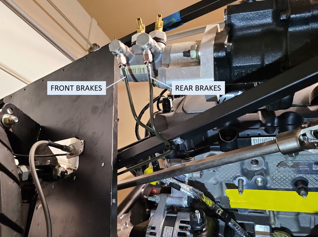
From the "T" fitting I ran another line around the upper left control arm mount, across the front of the X-tube, and around the PS upper right control arm mount. This is the same way many others have done it and keeps the line away from the front battery box mounting on the inside of the X-tube. I opted not to put the big coil loops in the line like the instructions indicated - I simply added a couple of extra bends to add some amount of flexibility in the lines (acts as a bit of strain relief on the tube).
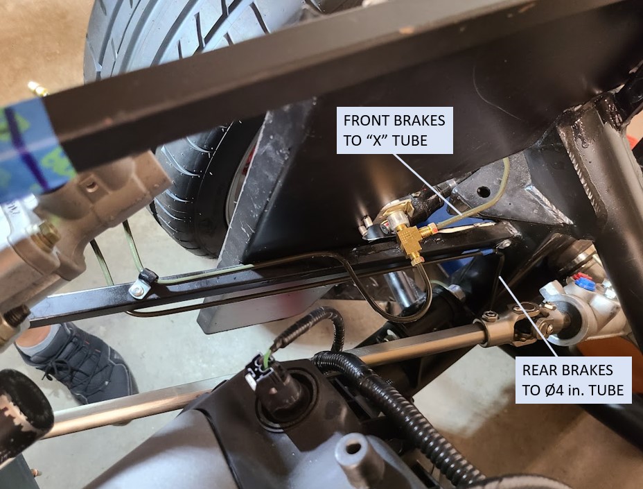

To run the lines from the hydroboost output to the rear, instead of running it down the front of the footbox, I elected to route the line across the bottom of the 3/4" frame tube toward the front (see pic above), then down the 2x2 beam to the Ø4 inch frame tube on the DS. The only reason for this was to keep the lines away from the header heat which runs right in front of the DS footbox.

After this, I ran a straight section toward the rear. Unfortunately, the pieces of tubing length I used, plus routing, meant I needed 3 sections of tubing to make this long run from the front DS "T" fitting to the rear DS "T" fitting. If I had to do this over again, I would try to make it all from one piece to eliminate all the extra couplings which just adds potential leak points. But I didn't have a tube straightener, so opted to use the straight pieces of tubing that I was able to find at the local auto parts store. Here's the run from the front to the rear, using female-female inverted flare coupler nuts.
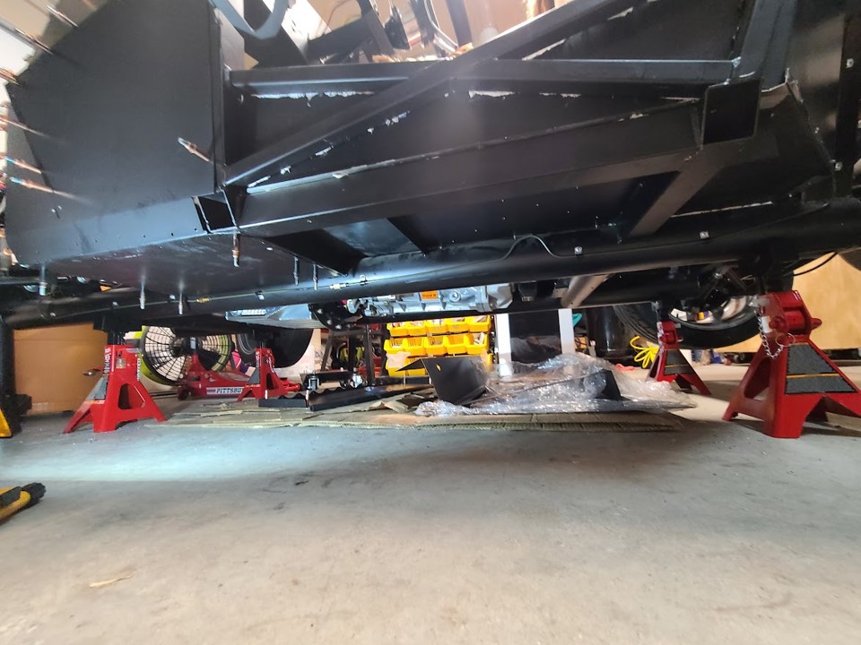
Once in the rear, I ran the line up the rear 2x2 frame member to the inside of the trunk bay and over to the rear "T" fitting on the DS.

From here, I ran another line across the 2x2 frame member over to the PS.

Here's a quick video showing ALL of the routing in one go:
Darryl [dbo_texas]
MKIV #9644 (build thread) (Index)
MK4 Complete Kit | Gen2 crate Coyote | Tremec T56, 3.55 IRS | power steering | hydroboost | dual roll bars | FFR carbon fiber dash | 18" Halibrands + Wilwoods | RT drop trunk kit & turn signal | front battery mount | saddle leather Intatrim Stoneleigh seats + interior accents
-
Post Thanks / Like - 0 Thanks, 1 Likes
-
Senior Member

Congrats on getting your brake lines installed. That's a good feeling. I'll be curious to hear later on once you're on the road what you think of the brake booster. Looking good.
Chris
Coupe complete kit delivered: 4/22/24.
Build Thread. Coyote. T-56. IRS w/3.55. Wilwoods. PS. HVAC. Side windows.
MK4 Complete kit.
Build Thread Index. Delivered: 10/15/2020. Legal: 7/25/23. Coyote Gen3. TKO600 (0.64 OD). IRS w/3.55. PS. Wilwoods. Sway bars. This build is dedicated to my son, Benjamin.
Build Thread.
-
Senior Member


Originally Posted by
460.465USMC

Congrats on getting your brake lines installed. That's a good feeling. I'll be curious to hear later on once you're on the road what you think of the brake booster. Looking good.
Thanks - I don't know why I was procrastinating getting the brake lines run - it wasn't too difficult and I actually liked the challenge. BTW I've been reading your build thread - great job documenting everything. I'm finding it to be a very useful resource.
Darryl [dbo_texas]
MKIV #9644 (build thread) (Index)
MK4 Complete Kit | Gen2 crate Coyote | Tremec T56, 3.55 IRS | power steering | hydroboost | dual roll bars | FFR carbon fiber dash | 18" Halibrands + Wilwoods | RT drop trunk kit & turn signal | front battery mount | saddle leather Intatrim Stoneleigh seats + interior accents
-
Post Thanks / Like - 1 Thanks, 0 Likes
-
Senior Member

-
Senior Member

-
Senior Member

You're on the right track. I had that exact issue with my #7750 build and posted this thread with the solution on the other forum. https://www.ffcars.com/threads/bled-...e-help.410697/. Mine had a solid pushrod. No adjustment or the nuts like yours. Without knowing how yours is made, would seem you could remove nuts to get the proper length. As long as there's one left to hold the length.
Build 1: Mk3 Roadster #5125. Sold 11/08/2014.
Build 2: Mk4 Roadster #7750. Sold 04/10/2017.
Build Thread
Build 3: Mk4 Roadster 20th Anniversary #8674. Sold 09/07/2020.
Build Thread and
Video.
Build 4: Gen 3 Type 65 Coupe #59. Gen 3 Coyote. Legal 03/04/2020.
Build Thread and
Video
Build 5: 35 Hot Rod Truck #138. LS3 and 4L65E auto. Rcvd 01/05/2021. Legal 04/20/2023.
Build Thread. Sold 11/9/2023.
-
Senior Member


Originally Posted by
edwardb

You're on the right track. I had that exact issue with my #7750 build and posted this thread with the solution on the other forum.
https://www.ffcars.com/threads/bled-...e-help.410697/. Mine had a solid pushrod. No adjustment or the nuts like yours. Without knowing how yours is made, would seem you could remove nuts to get the proper length. As long as there's one left to hold the length.
Thanks Paul for confirming my suspicion. I read through your post on #7750 and looks to be the exact same issue, as you mention. I'll pull it back apart and see if I can adjust the nuts to get the right overall length.
Darryl [dbo_texas]
MKIV #9644 (build thread) (Index)
MK4 Complete Kit | Gen2 crate Coyote | Tremec T56, 3.55 IRS | power steering | hydroboost | dual roll bars | FFR carbon fiber dash | 18" Halibrands + Wilwoods | RT drop trunk kit & turn signal | front battery mount | saddle leather Intatrim Stoneleigh seats + interior accents
-
Senior Member


Originally Posted by
dbo_texas

I used one of the FFR aluminum brackets that has the FFR logo on it....I forget what this is typically used for (maybe the fuse box?). Anyhow, I repurposed it and mounted it to the back of the reservoir.

Hi Darryl,
Your gut is right on the bracket. In the manual they show it installed on top of the PS FB, and attach the Coyote PDB (AKA fuse box) to it. This is where I mounted mine. Not a huge deal as some guys mount the PDB elsewhere. There's plenty of Coyote wire harness length to give you some leeway to mount it to the firewall, for example. Not a big deal if you don't have the bracket. Or, you can make another one if you want to mount it on the FB.
Chris
Coupe complete kit delivered: 4/22/24.
Build Thread. Coyote. T-56. IRS w/3.55. Wilwoods. PS. HVAC. Side windows.
MK4 Complete kit.
Build Thread Index. Delivered: 10/15/2020. Legal: 7/25/23. Coyote Gen3. TKO600 (0.64 OD). IRS w/3.55. PS. Wilwoods. Sway bars. This build is dedicated to my son, Benjamin.
Build Thread.
-
Senior Member

Hydroboost pushrod adjustment
To close the loop on the Hydroboost discussion - I confirmed w/ Mike Forte that I needed to shorted the pushrod in they hydroboost. This should be pretty much flush (or very small gap, like .010" - .020") with the cup/receiver in the master cylinder. I took it apart and remeasured, but found the actual interference was exactly 0.25", not the 0.386" I measured last time. Looks like when I measured before the brake pedal wasn't pushed all the way to the stop. I measured multiple times just to be sure. Anyhow, to adjust the length I just had to remove the middle nut from the pushrod which was exactly 0.25" thick. I put a hefty amount of blue Loctite on the ball stud end threads and tightened it down - I was worried that getting rid of that middle lock nut would allow it to vibrate loose but with the Loctite I think it will be OK. If anyone disagrees let me know!

I do need to still replace the hydroboost power steering return nipple (5/16" thread) with a Hydrotech HBS9101 06AN adapter (or equivalent). This will allow me to run a braided stainless steel line from the return.
Last edited by dbo_texas; 12-05-2022 at 10:22 PM.
Darryl [dbo_texas]
MKIV #9644 (build thread) (Index)
MK4 Complete Kit | Gen2 crate Coyote | Tremec T56, 3.55 IRS | power steering | hydroboost | dual roll bars | FFR carbon fiber dash | 18" Halibrands + Wilwoods | RT drop trunk kit & turn signal | front battery mount | saddle leather Intatrim Stoneleigh seats + interior accents
-
12-05-2022, 10:20 PM
#100
Senior Member

-
12-13-2022, 09:10 AM
#101
Senior Member

Pedal Adjustment and Clutch Safety Switch Mounting
I was looking over the Wilwood pedal setup in my build (assembled by previous builder) and see that they mounted both of the FFR provided switches for the brake and clutch (newer style with both NO & NC contact pairs). These are mounted on the little tabs in front of the pedal arms. I'm leaving the brake switch as-is because it seems to work well and triggers almost as soon as you touch the brake pedal. However, I'd like to remove the FFR clutch safety switch (mounted similar to the brake pedal switch) and use the switch provided with the Coyote Controls Pack instead because it triggers only when the clutch is pushed all the way in which I think is the intended use. I don't think I have either bracket shown below (I found this image on the forum), or at least I can't find them. They look laser cut so I assume they came from FFR. I have seen some people make their own custom mounts but I'd rather use FFR parts if they are available (will save me time). The Coyote Install Instructions (Gen 2) show the switch bracket and the actuator bracket mounted to the clutch quadrant, but since I'm using a hydraulic clutch I think I need something like this instead. I'm guessing at some point FFR added this other version which doesn't require the clutch quadrant for mounting? Can anyone confirm this?

My second question is regarding the pedal positioning. I noticed that my brake pedal arm is currently hitting the 3/4" frame tube. I've seen on the forum that it shouldn't be this way because it means the MC piston is travel limited and not returning to the full resting position. Do I just need to adjust the threaded rod until the pedal arm clears the frame? What gap is appropriate here? I didn't see anything in the FFR instructions talking about this.
Finally - after reading more on the forum, and seeing the brake pedal arm issue, I'm wondering if the clutch pedal needs to be adjusted at all. How do you determine if the travel in the clutch MC is too much or too little which could impact the internal seals? I've seen people have added hard stops for the clutch pedal (to limit travel when depressed). Is this documented anywhere on how to check/adjust this? I have a Forte hydraulic clutch but haven't hooked it up yet. I think Forte adjusted the slave pushrod when he shipped the drivetrain (Gen2 + T56 + hydraulic clutch) but I'll check that to see what the travel is on the actual clutch fork - but can't do that until I hook up the hydraulic lines and bleed the system. Any guidance on how to make sure the pedal travel is appropriate for the clutch MC would be appreciated!
Darryl [dbo_texas]
MKIV #9644 (build thread) (Index)
MK4 Complete Kit | Gen2 crate Coyote | Tremec T56, 3.55 IRS | power steering | hydroboost | dual roll bars | FFR carbon fiber dash | 18" Halibrands + Wilwoods | RT drop trunk kit & turn signal | front battery mount | saddle leather Intatrim Stoneleigh seats + interior accents
-
12-13-2022, 10:57 AM
#102
Senior Member

1. Yes, you want the Coyote control pack switch on the clutch pedal. It's at the bottom of the pedal motion as you described, so an actual safety device. At the top doesn't mean much. Plus the Coyote provided switch plugs into the control pack harness directly. Not a big deal, but worth something. Yes, those are the brackets from FFR. My earlier kit had them, but only for the cable version. 99% certain they now offer them when using a hydraulic setup. Best to contact them. A little off topic, but some wire this function into the neutral switch on the trans. Some even do both. Just do something.
2. Yes, you need the brake pedal to stop firmly short of that 3/4" tube for exactly the reason you mention. Yes, adjust the pushrod into the Wilwood clevis to move it. I don't think the actual clearance is critical. Just that it doesn't stop there.
3. For the clutch, I'm a fan of having the clutch at the same height as the brake pedal. Not everyone does it that way. But that's my preference. Once the brake pedal is adjusted, I adjust the clutch pedal to be the same height. Also check the accelerator to see if I have a decent "heel and toe" setup. Not that I'm a race driver. Just find this to be the most comfortable. You will be able to check to see if this provides the proper amount of travel for your clutch once you have it installed and bled. Just take it slow to not overdrive the slave and pop it out of the bore. (Not that I would know anything about that...). My experience is if the clutch MC is sized properly, you won't exceed the slave travel and the clutch will be fully disengaged. You can decide at that point if a stop is required. Likely it will and many recommend them out of caution. But just remember, if you're stopping the clutch pedal way short of the floor, you're trading travel for effort. Best to get the MC sized properly. Your left leg will thank you.
Last edited by edwardb; 12-13-2022 at 11:00 AM.
Build 1: Mk3 Roadster #5125. Sold 11/08/2014.
Build 2: Mk4 Roadster #7750. Sold 04/10/2017.
Build Thread
Build 3: Mk4 Roadster 20th Anniversary #8674. Sold 09/07/2020.
Build Thread and
Video.
Build 4: Gen 3 Type 65 Coupe #59. Gen 3 Coyote. Legal 03/04/2020.
Build Thread and
Video
Build 5: 35 Hot Rod Truck #138. LS3 and 4L65E auto. Rcvd 01/05/2021. Legal 04/20/2023.
Build Thread. Sold 11/9/2023.
-
Post Thanks / Like - 0 Thanks, 1 Likes
-
12-13-2022, 02:49 PM
#103
Senior Member


Originally Posted by
edwardb

1. Yes, you want the Coyote control pack switch on the clutch pedal. It's at the bottom of the pedal motion as you described, so an actual safety device. At the top doesn't mean much. Plus the Coyote provided switch plugs into the control pack harness directly. Not a big deal, but worth something. Yes, those are the brackets from FFR. My earlier kit had them, but only for the cable version. 99% certain they now offer them when using a hydraulic setup. Best to contact them. A little off topic, but some wire this function into the neutral switch on the trans. Some even do both. Just do something.
2. Yes, you need the brake pedal to stop firmly short of that 3/4" tube for exactly the reason you mention. Yes, adjust the pushrod into the Wilwood clevis to move it. I don't think the actual clearance is critical. Just that it doesn't stop there.
3. For the clutch, I'm a fan of having the clutch at the same height as the brake pedal. Not everyone does it that way. But that's my preference. Once the brake pedal is adjusted, I adjust the clutch pedal to be the same height. Also check the accelerator to see if I have a decent "heel and toe" setup. Not that I'm a race driver. Just find this to be the most comfortable. You will be able to check to see if this provides the proper amount of travel for your clutch once you have it installed and bled. Just take it slow to not overdrive the slave and pop it out of the bore. (Not that I would know anything about that...). My experience is if the clutch MC is sized properly, you won't exceed the slave travel and the clutch will be fully disengaged. You can decide at that point if a stop is required. Likely it will and many recommend them out of caution. But just remember, if you're stopping the clutch pedal way short of the floor, you're trading travel for effort. Best to get the MC sized properly. Your left leg will thank you.
Thanks Paul - really appreciate the detailed response on all items. I've reached out to FFR on the clutch switch brackets, as I was already on the phone with them ordering the floor mats (finally in stock - woohoo!). They will get back to me on the brackets. As for the clutch MC, I have a 0.75 size provided by Forte so I'll see how that feels with his clutch setup. I've seen others using that same size with good results.
Darryl [dbo_texas]
MKIV #9644 (build thread) (Index)
MK4 Complete Kit | Gen2 crate Coyote | Tremec T56, 3.55 IRS | power steering | hydroboost | dual roll bars | FFR carbon fiber dash | 18" Halibrands + Wilwoods | RT drop trunk kit & turn signal | front battery mount | saddle leather Intatrim Stoneleigh seats + interior accents
-
12-14-2022, 05:01 PM
#104
Senior Member

-
12-15-2022, 04:39 PM
#105
Senior Member


Originally Posted by
dbo_texas

As for the clutch MC, I have a 0.75 size provided by Forte so I'll see how that feels with his clutch setup. I've seen others using that same size with good results.
Hi Darryl,
Thought I'd pass along a tip given to me from Fman in case it also applies to your build. He was sent the wrong size. For the hydraulic clutch setup from Forte, the Wilwood MC should be 13/16" (0.81 inches). Thanks to his tip, I was able to confirm early on Forte sent me 0.81. This is true for the TKO600; I know you have the T-56, so maybe this won't apply. But, definitely worth confirming with Forte sooner rather than later.
Chris
Coupe complete kit delivered: 4/22/24.
Build Thread. Coyote. T-56. IRS w/3.55. Wilwoods. PS. HVAC. Side windows.
MK4 Complete kit.
Build Thread Index. Delivered: 10/15/2020. Legal: 7/25/23. Coyote Gen3. TKO600 (0.64 OD). IRS w/3.55. PS. Wilwoods. Sway bars. This build is dedicated to my son, Benjamin.
Build Thread.
-
12-16-2022, 03:14 PM
#106
Senior Member


Originally Posted by
dbo_texas

I was looking over the Wilwood pedal setup in my build (assembled by previous builder) and see that they mounted both of the FFR provided switches for the brake and clutch (newer style with both NO & NC contact pairs). These are mounted on the little tabs in front of the pedal arms. I'm leaving the brake switch as-is because it seems to work well and triggers almost as soon as you touch the brake pedal. However, I'd like to remove the FFR clutch safety switch (mounted similar to the brake pedal switch) and use the switch provided with the Coyote Controls Pack instead because it triggers only when the clutch is pushed all the way in which I think is the intended use. I don't think I have either bracket shown below (I found this image on the forum), or at least I can't find them. They look laser cut so I assume they came from FFR. I have seen some people make their own custom mounts but I'd rather use FFR parts if they are available (will save me time). The Coyote Install Instructions (Gen 2) show the switch bracket and the actuator bracket mounted to the clutch quadrant, but since I'm using a hydraulic clutch I think I need something like this instead. I'm guessing at some point FFR added this other version which doesn't require the clutch quadrant for mounting?
Can anyone confirm this?

My second question is regarding the pedal positioning. I noticed that my brake pedal arm is currently hitting the 3/4" frame tube. I've seen on the forum that it shouldn't be this way because it means the MC piston is travel limited and not returning to the full resting position.
Do I just need to adjust the threaded rod until the pedal arm clears the frame? What gap is appropriate here? I didn't see anything in the FFR instructions talking about this.
Finally - after reading more on the forum, and seeing the brake pedal arm issue, I'm wondering if the clutch pedal needs to be adjusted at all. How do you determine if the travel in the clutch MC is too much or too little which could impact the internal seals? I've seen people have added hard stops for the clutch pedal (to limit travel when depressed). Is this documented anywhere on how to check/adjust this? I have a Forte hydraulic clutch but haven't hooked it up yet. I think Forte adjusted the slave pushrod when he shipped the drivetrain (Gen2 + T56 + hydraulic clutch) but I'll check that to see what the travel is on the actual clutch fork - but can't do that until I hook up the hydraulic lines and bleed the system.
Any guidance on how to make sure the pedal travel is appropriate for the clutch MC would be appreciated!
For anyone following - I confirmed with Factory Five that the brackets shown do come included w/ the Coyote Install Kit and is FFR p/n 16922 - the one shown can be used specifically with a hydraulic clutch setup.
Darryl [dbo_texas]
MKIV #9644 (build thread) (Index)
MK4 Complete Kit | Gen2 crate Coyote | Tremec T56, 3.55 IRS | power steering | hydroboost | dual roll bars | FFR carbon fiber dash | 18" Halibrands + Wilwoods | RT drop trunk kit & turn signal | front battery mount | saddle leather Intatrim Stoneleigh seats + interior accents
-
12-16-2022, 06:36 PM
#107
Senior Member


Originally Posted by
460.465USMC

Hi Darryl,
Thought I'd pass along a tip given to me from Fman in case it also applies to your build. He was sent the wrong size. For the hydraulic clutch setup from Forte, the Wilwood MC should be 13/16" (0.81 inches). Thanks to his tip, I was able to confirm early on Forte sent me 0.81. This is true for the TKO600; I know you have the T-56, so maybe this won't apply. But, definitely worth confirming with Forte sooner rather than later.
Thanks for the tip! I checked my MC on the clutch and it was 3/4" --> looks like the original builder used one of the FFR supplied MCs that came w/ the kit. I asked Mike Forte which size should be used w/ my Gen2 Coyote + T56 and he confirmed I should be using the 13/16 size and definitely NOT the 3/4 size. So I dug through some boxes because I remembered coming across 2 extra MCs about a year ago, and sure enough one of them was the 13/16 Wilwood MC so I'm guessing that is the one that came w/ the hydroboost from Forte. My only thought is that the original builder didn't realize it was a different size than the one FFR provides in the kit. I'll be swapping that out for sure to use the 13/16 size. So thanks again for the tip - you likely saved me a lot of troubleshooting down the road when I bleed the system and test it out.
Darryl [dbo_texas]
MKIV #9644 (build thread) (Index)
MK4 Complete Kit | Gen2 crate Coyote | Tremec T56, 3.55 IRS | power steering | hydroboost | dual roll bars | FFR carbon fiber dash | 18" Halibrands + Wilwoods | RT drop trunk kit & turn signal | front battery mount | saddle leather Intatrim Stoneleigh seats + interior accents
-
12-19-2022, 12:05 PM
#108
Senior Member

Hydroboost Fix and Brake Pedal Arm Positioning
After a lot of research I found that with my setup, the brake pedal arm was hitting the frame which prevented the hydroboost pushrod from returning to its resting position. In post #94 I discussed shortening the hydroboost pushrod because it was interfering with the master cylinder pushrod in the resting position. Well it turns out this interference was due to the pedal arm issue. To resolve this, I had to get rid of the pedal arm interference and then re-adjust the hydroboost pushrod length (grow length back to original length). Good thing I saved the lock nut!
Adjusting the pedal arm position turned out to be way more painful that I thought. I initially tried turning the threaded rod into the clevis on the pedal arm, but found that the rod bottomed out on the brake arm (i.e. it was too long). With it bottomed out, the pedal arm was still hitting the frame tube. My only option at this point was to completely remove the hydroboost so that I could cut the threaded stud shorter by about 1/4". Easier said than done. One of the bolts for the hydroboost is almost impossible to get to as it us buried by the Wilwood pedal box, including the Coyote pedal module. After about an hour of micro turns (that's all the wrench had clearance for) I finally got the nut off and was able to remove the hydroboost.
I then marked and cut off about 1/4" inch off the bolt. This looks like Forte welds a 3/8-16 bolt to the stock GM hydroboost pushrod. I also added a jam nut to the rod since it didn't have one from the previous builder - after talking to Forte he said it would be a good idea to add the jam nut to lock everything in place. I didn't have a thin nut so I used an angle grinder with the sanding wheel and made my own out of a standard 3/8 nut.
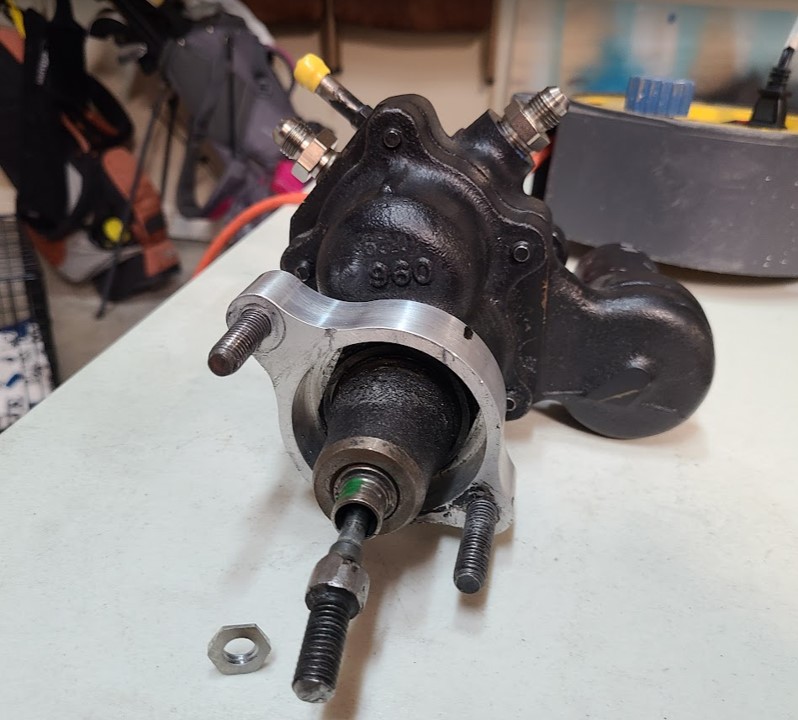
After this was done, I re-installed the hydroboost and adjusted the thread depth into the clevis until it pulled the brake pedal arm off the frame tube by about 1/8". I made sure the hydroboost piston was at full travel to resting position, then re-measured the interface between hydroboost pushrod and the master cylinder pushrod. I had to increase the length of the hydroboost pushrod back to its original length from before I had made the previous adjustment.
Once the bolts were re-installed (again, that one bolt was a PITA), everything was good to go.

Here's a picture of the clearance to the brake pedal arm:

The last step was to adjust the brake switch position so that it fires almost as soon as the pedal arm starts to travel:

Last edited by dbo_texas; 12-20-2022 at 12:17 PM.
Darryl [dbo_texas]
MKIV #9644 (build thread) (Index)
MK4 Complete Kit | Gen2 crate Coyote | Tremec T56, 3.55 IRS | power steering | hydroboost | dual roll bars | FFR carbon fiber dash | 18" Halibrands + Wilwoods | RT drop trunk kit & turn signal | front battery mount | saddle leather Intatrim Stoneleigh seats + interior accents
-
12-19-2022, 12:19 PM
#109
Senior Member

Clutch Safety Switch Mounting
As previously mentioned, my build had a 3/4" MC installed on the clutch. Per Forte, and as others have mentioned, with his setup the proper MC is 13/16 for Forte's hydraulic clutch setup. Luckily the previous builder had the 13/16 MC in a box still, so I went ahead and swapped that out - easy. I did have to cut the 5/8" off the threaded rod but that was simple and quick. I then adjusted the clutch pedal position to be even with the brake pedal (just thread the MC pushrod into the clevis until the pedal position is where you want). This leaves about 8.5" from the face of the pedal to the firewall (just for reference). After bleeding and testing the clutch actuation, I may need to add a pedal stop to the firewall (TBD) - I'll be looking to make sure the piston in the slave cylinder isn't extending beyond it's range. Some have had it travel too far and the piston actually pops out of the slave cylinder. So if this happens I'll add a pedal stop to limit clutch pedal travel.

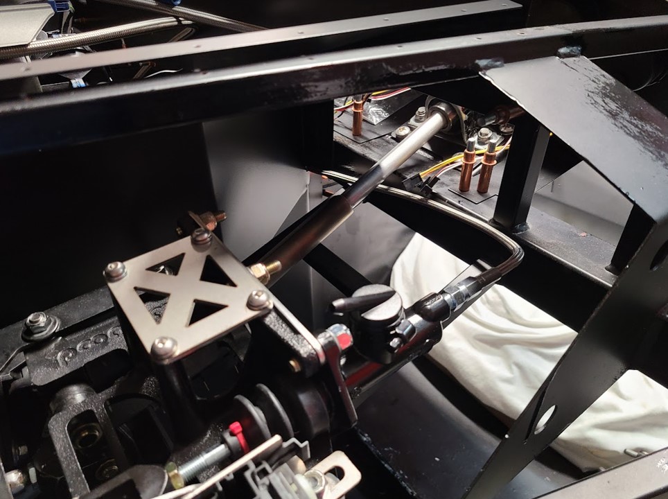
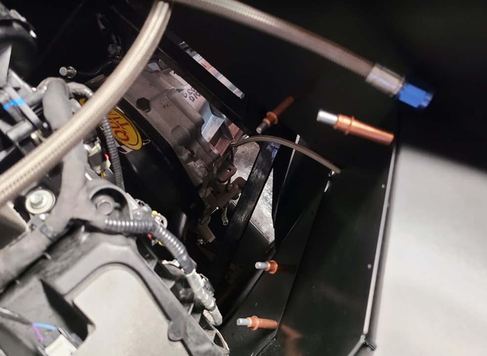
Next up, I needed to mount the clutch safety switch provided by Ford with the Coyote Controls Pack. This switch gets mounted using some brackets provided by FFR with the Coyote Install Kit. My kit was from 2019, so this was before FFR started providing brackets specifically for those with hydraulic clutch setups. But others on the forum had made it work using the provided bracket which was intended to mount to the clutch quadrant. All I had to do with drill one extra hole in the bracket and tap a 1/4-20 thread into the clutch clevis. I could then use the existing pivot on the clevis to prevent the bracket from rotating, and drive in a screw to secure it. I used a washer on the backside to match the offset of the brass washer and lock ring on the pivot. This worked like a charm. Here are some pictures - you can see I marked where the switch closes the circuit and where the end of travel is. I set the position of the switch (adjustable with the FFR bracket slots) so that the circuit closes close to the end of clutch pedal arm travel. This should guarantee the clutch is fully disengaged before triggering the switch. One thing I will check once I bleed the system and verify slave cylinder piston travel and clutch actuation, is whether or not I need to move the switch a little bit based on final pedal arm travel. If I have to use a clutch pedal stop, then I might need to shift the switch forward but that's easy since it is slotted and I would be moving it forward so it triggers sooner.
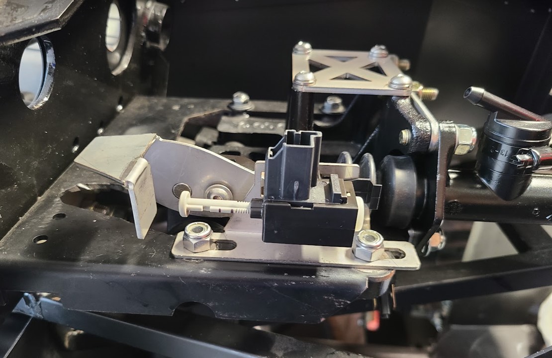
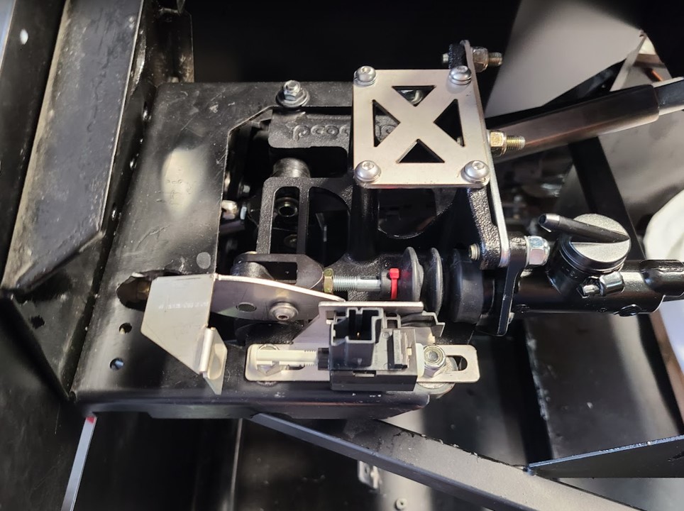
Here's a video showing the switch actuation and testing:
Finally, I hooked up the flex line so I could mock up where to route it to the transmission. I think I'll do as some others have done and drill a new hole in the DS inside footbox panel and use a grommet to pass the flex line out. Very similar to how I have it shown in these photos, just a little cleaner than trying to squeeze it between the gaps in the panels which doesn't really work.
Last edited by dbo_texas; 12-20-2022 at 12:24 PM.
Darryl [dbo_texas]
MKIV #9644 (build thread) (Index)
MK4 Complete Kit | Gen2 crate Coyote | Tremec T56, 3.55 IRS | power steering | hydroboost | dual roll bars | FFR carbon fiber dash | 18" Halibrands + Wilwoods | RT drop trunk kit & turn signal | front battery mount | saddle leather Intatrim Stoneleigh seats + interior accents
-
12-26-2022, 06:51 PM
#110
Senior Member

Radiator Mount - Breeze Fan Shroud + Upper/Lower Mounts
Today with a little bit of time off from work I decided to start tackling the cooling system. I wanted to mock up the radiator mounting. I used the Breeze fan shroud as well as upper and lower radiator mounts (which Santa conveniently delivered just yesterday!). Here are the Breeze part numbers used:
As usual, the Breeze instructions are straight forward. I started with the fan shroud. This has holes to mount the stock FFR radiator fan - just attach with 4 provided screws and nylock nuts.

Next up, I went ahead and mounted the upper mount hinged bracket to the radiator upper front flange. I did this before mounting the shroud to the radiator because some of the hardware has to go through the upper hinged bracket and needs to be drilled out. So I marked my rivet holes, and drilled them through the radiator flange and hinge bracket flange, making sure the actual hinge pivot faces rearward. Using cleco's to tack it together for now, because ultimately I will disassemble and paint the radiator and brackets black. There is a special paint made specifically for painting the radiator, if that is the look you are going for. Here you can see the upper hinge bracket with rivet holes drilled.
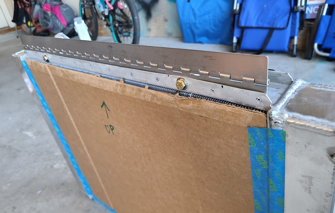
I then mounted the shroud to the FFR radiator (AFCO). The fan shroud has 2 holes on the top that you mark on the back of the radiator flange, then drill through both radiator flanges and the upper hinge mount, then insert a spacer (between the flanges). Once the top was held in place with the bolts, I marked and drilled the two lower holes and secured with the provided screws, washers, and nuts. I Here's a good view showing what it looks like after complete:

Next up I went ahead and mounted the lower radiator mount to the frame. For this I just followed the instructions - nothing much to it really. The kit comes with a square tube, a couple of pieces of hose to slide over the tube, and some mounting brackets and hardware. I centered the radiator, marked and notched the tube to clear the weld beads on the bottom of the radiator, and them temp mounted it all to the frame. I used a floor jack to hold the weight of the radiator, then adjusted until I got the 51° angle required (noted in the instructions). I then marked where the brackets were on the frame, removed it all and drilled the holes in the frame for the lower mount brackets.

Here's what the lower mount bracket looks like installed:

And a close-up of how it mounts to the frame:

I temp mounted everything and realized why the Breeze instructions say to cut away the stock FFR radiator mounts (these are the two small sections of 3/4" tube welded below the 3/4" cross tube). The upper hinge pivot hits the stock FFR mount. By cutting it away, you create clearance for the hinge which lets the flange sit flush with the cross tube.

So what is left for me to to? I need to remove all the parts/brackets and spray paint everything black. I'll cut the stock FFR radiator mounts off the frame and then touch up everything with paint. For the radiator I'll use the special radiator paint, and for all the Breeze brackets and frame touch-ups I'll use Rustoleum Matte Custom Shop Black - P/N 263422 - which does a decent job of matching the FFR powder coat used on the frame. Once painted, I can re-mount everything, rivet the upper hinge, and bolt everything down.
Darryl [dbo_texas]
MKIV #9644 (build thread) (Index)
MK4 Complete Kit | Gen2 crate Coyote | Tremec T56, 3.55 IRS | power steering | hydroboost | dual roll bars | FFR carbon fiber dash | 18" Halibrands + Wilwoods | RT drop trunk kit & turn signal | front battery mount | saddle leather Intatrim Stoneleigh seats + interior accents
-
01-02-2023, 06:13 PM
#111
Senior Member

-
01-02-2023, 06:24 PM
#112
Senior Member

Hood Hinges Installation & questions on gas strut and expansion tank mounting
Having finalized the radiator mounting, next up on my list is the coolant expansion tank. I bought the Mishimoto MMRT-MUS-15EBK tank which is very similar to the Moroso tank many Coyote installers use. I went with the Mishimoto tank because #1 it is black, and #2 it has a little fill-level indicator tube on the side which I like. However, in order to place the expansion tank, I needed to go ahead and mount the hood hinge brackets since this will dictate how close to the side of the engine bay I can position the tank.
I had a couple of helpers to assemble the hinges. Everything is pretty straight forward following the FFR instructions, and we didn't have any issues with assembly.

Here's one of the hinges assembled and ready to mount:
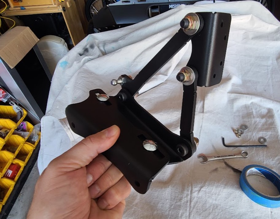
And installed:


Question #1: Is the gas strut supposed to be this long? I haven't mounted to bracket with the ball-stud to the hood yet, but in the uncompressed state the strut is hitting my triple reservoir. I had marked the frame with blue tape where I thought the strut length would stop, based on reading other build threads. Just wondering if this is a non-issue once the strut gets compressed and mounted to the hood bracket?

Question #2: For the expansion tank, should I plan on mounting it as close to the hood hinge on the PS as possible? I'm thinking I'll need room for the air intake elbow. Also, are there any recommendations on how high the tank should be sitting? I couldn't find any mentions of vertical position of the expansion tank so that the cap clears the hood. Any recommendations?

Darryl [dbo_texas]
MKIV #9644 (build thread) (Index)
MK4 Complete Kit | Gen2 crate Coyote | Tremec T56, 3.55 IRS | power steering | hydroboost | dual roll bars | FFR carbon fiber dash | 18" Halibrands + Wilwoods | RT drop trunk kit & turn signal | front battery mount | saddle leather Intatrim Stoneleigh seats + interior accents
-
01-02-2023, 11:54 PM
#113
Senior Member

1. The only time the strut is that length is when it's uncompressed while the hood is open. With the hood closed it's compressed and you'll be fine. You just have to make sure the location of the ball stud on the hood doesn't bottom out the strut when closed.
2. I don't have a Roadster here to give you an exact measurement. But this thread has some discussion and a lot of pictures. If you were using the same Moroso tank a lot of us use, there's specific information. But perhaps there's enough to go on. https://thefactoryfiveforum.com/show...expansion-tank. The hood is arched more than you might think. So there's plenty of clearance if placed properly.
Build 1: Mk3 Roadster #5125. Sold 11/08/2014.
Build 2: Mk4 Roadster #7750. Sold 04/10/2017.
Build Thread
Build 3: Mk4 Roadster 20th Anniversary #8674. Sold 09/07/2020.
Build Thread and
Video.
Build 4: Gen 3 Type 65 Coupe #59. Gen 3 Coyote. Legal 03/04/2020.
Build Thread and
Video
Build 5: 35 Hot Rod Truck #138. LS3 and 4L65E auto. Rcvd 01/05/2021. Legal 04/20/2023.
Build Thread. Sold 11/9/2023.
-
01-09-2023, 12:08 AM
#114
Senior Member

Mishimoto Coolant Expansion Tank MMRT-MUS-15EBK Install
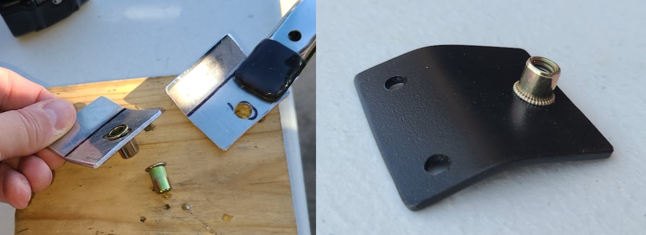
This weekend I finished mounting the Mishimoto MMRT-MUS-15EBK expansion tank. This one is similar to the Moroso tank many folks use, just with the included sight tube to see fluid level. I opted for the matte black version (they also make a bare aluminum finish). To mount this, I needed to make 3 brackets - two for the mounting flange, and one to support the bottom of the tank. Took a little longer than I anticipated, but I'm pretty happy with the end result.
Here's a pic of the upper brackets. All are made with 0.100" aluminum stock and 1/4-20 rivet nuts. With the Breeze upper radiator hinge mount in place, I was able to wedge this bracket between the hinge and the 3/4 tube and bend it so that the mounting flange is flat/level. It is positioned on the 3/4 frame tube so that the expansion tank flange is even with the bottom of the 3/4 frame tube.
Upper brackets get riveted to the underside of the 3/4 frame tube. I had to remove the radiator to get access to drill the rivet holes.
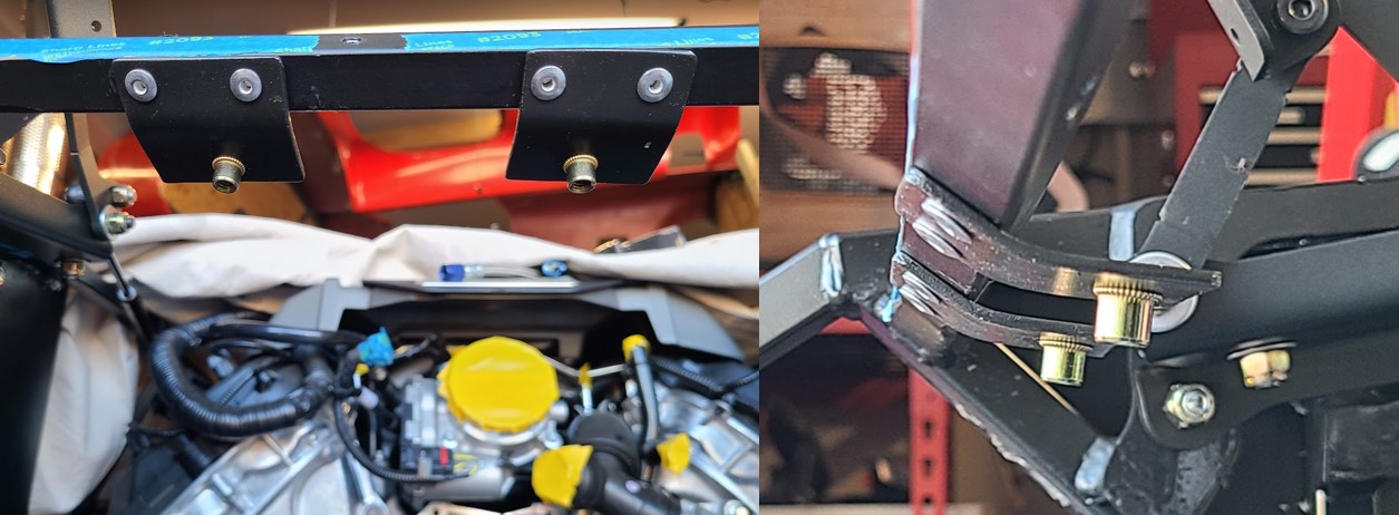
Looks like this with the tank mounted:

I needed to reinstall the radiator in order to figure out how to fab the lower bracket. Due to the position of the tab on the tank, it actually extends slightly past the Breeze fan shroud. After positioning and mocking up the bracket out of cardboard, I fabricated the lower bracket, marked the position on the shroud, and riveted it in place.

Here's how the tab on the bottom of the tank mates with the lower bracket. After bolting in place, the overall assembly is rock solid and doesn't move at all. I'm pretty happy with the result.

Here's the final product, showing reference dimension from center of the hinge mount on the frame:
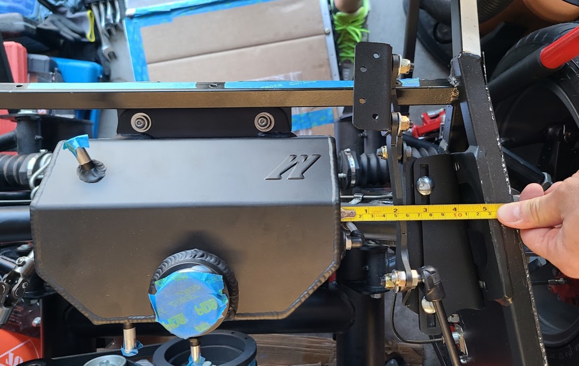
Side view:
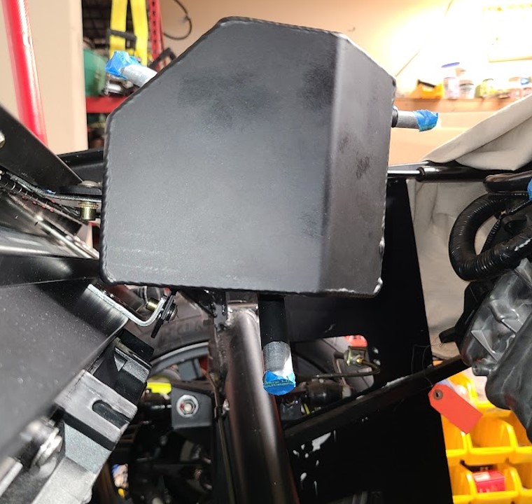
Darryl [dbo_texas]
MKIV #9644 (build thread) (Index)
MK4 Complete Kit | Gen2 crate Coyote | Tremec T56, 3.55 IRS | power steering | hydroboost | dual roll bars | FFR carbon fiber dash | 18" Halibrands + Wilwoods | RT drop trunk kit & turn signal | front battery mount | saddle leather Intatrim Stoneleigh seats + interior accents
-
Post Thanks / Like - 0 Thanks, 1 Likes
-
01-09-2023, 06:17 AM
#115
Senior Member

That tank looks to be taller than the Moroso tanks many of us have used. Hard to tell from the angle of your picture. But seems that location might interfere with the hood. I can't give you a specific measurement because my Roadster build isn't around here any more. But these threads have a lot of pictures. Maybe mock up your hood as I show from my build thread. https://thefactoryfiveforum.com/show...l=1#post220495. Another thread where the Moroso tank is discussed and has pictures. https://thefactoryfiveforum.com/show...expansion-tank.
Build 1: Mk3 Roadster #5125. Sold 11/08/2014.
Build 2: Mk4 Roadster #7750. Sold 04/10/2017.
Build Thread
Build 3: Mk4 Roadster 20th Anniversary #8674. Sold 09/07/2020.
Build Thread and
Video.
Build 4: Gen 3 Type 65 Coupe #59. Gen 3 Coyote. Legal 03/04/2020.
Build Thread and
Video
Build 5: 35 Hot Rod Truck #138. LS3 and 4L65E auto. Rcvd 01/05/2021. Legal 04/20/2023.
Build Thread. Sold 11/9/2023.
-
01-09-2023, 10:06 AM
#116
Senior Member

Thanks for the feedback - I perhaps incorrectly assumed the Mishimoto tank was the same as the Moroso from mounting flange to top of tank. I'm checking with Lidodrip to get more details on his positioning since he has the same Mishimoto tank as me. Looks like he got some similar feedback and repositioned his tank (although it looks fairly close to where mine is and he said it clears). Here's his THREAD for reference. I'll report back once I have it figured out.
In your hood placement mockup, looks like you have a couple of small wood blocks the hood is sitting on (based on measurements from your already built MK4). Do you happen to remember the thickness of those blocks? They look to be about 3/4" thick. I'm thinking it might be good for me to do a similar mockup and also mount the air intake elbow as I'm a little worried about that as well.
Last edited by dbo_texas; 01-09-2023 at 10:34 AM.
Reason: *added question about hood mockup
Darryl [dbo_texas]
MKIV #9644 (build thread) (Index)
MK4 Complete Kit | Gen2 crate Coyote | Tremec T56, 3.55 IRS | power steering | hydroboost | dual roll bars | FFR carbon fiber dash | 18" Halibrands + Wilwoods | RT drop trunk kit & turn signal | front battery mount | saddle leather Intatrim Stoneleigh seats + interior accents
-
01-09-2023, 04:19 PM
#117
Senior Member


Originally Posted by
dbo_texas

Thanks for the feedback - I perhaps incorrectly assumed the Mishimoto tank was the same as the Moroso from mounting flange to top of tank. I'm checking with Lidodrip to get more details on his positioning since he has the same Mishimoto tank as me. Looks like he got some similar feedback and repositioned his tank (although it looks fairly close to where mine is and he said it clears). Here's his
THREAD for reference. I'll report back once I have it figured out.
In your hood placement mockup, looks like you have a couple of small wood blocks the hood is sitting on (based on measurements from your already built MK4). Do you happen to remember the thickness of those blocks? They look to be about 3/4" thick. I'm thinking it might be good for me to do a similar mockup and also mount the air intake elbow as I'm a little worried about that as well.
Yes, they're 3/4" thick blocks.
Build 1: Mk3 Roadster #5125. Sold 11/08/2014.
Build 2: Mk4 Roadster #7750. Sold 04/10/2017.
Build Thread
Build 3: Mk4 Roadster 20th Anniversary #8674. Sold 09/07/2020.
Build Thread and
Video.
Build 4: Gen 3 Type 65 Coupe #59. Gen 3 Coyote. Legal 03/04/2020.
Build Thread and
Video
Build 5: 35 Hot Rod Truck #138. LS3 and 4L65E auto. Rcvd 01/05/2021. Legal 04/20/2023.
Build Thread. Sold 11/9/2023.
-
01-09-2023, 11:05 PM
#118
Senior Member


Originally Posted by
dbo_texas

Thanks for the feedback - I perhaps incorrectly assumed the Mishimoto tank was the same as the Moroso from mounting flange to top of tank. I'm checking with Lidodrip to get more details on his positioning since he has the same Mishimoto tank as me. Looks like he got some similar feedback and repositioned his tank (although it looks fairly close to where mine is and he said it clears). Here's his
THREAD for reference. I'll report back once I have it figured out.
Hello Darryl, I have updated the thread you referenced regarding the Mishimoto tank. Hopefully this helps, I have at least 1" of clearance between the hood and tank cap.
James
Mk4 Roadster #9974 - Picked Up 1/2021. Complete kit, Gen 2 Ford Coyote / TKX, IRS. Completed 9/2023
-
01-10-2023, 04:17 PM
#119
Senior Member


Originally Posted by
Lidodrip

Hello Darryl, I have updated the thread you referenced regarding the Mishimoto tank. Hopefully this helps, I have at least 1" of clearance between the hood and tank cap.
James
Thanks a lot ->> I'll take a look this week and confirm my positioning. This is a huge help!
Darryl [dbo_texas]
MKIV #9644 (build thread) (Index)
MK4 Complete Kit | Gen2 crate Coyote | Tremec T56, 3.55 IRS | power steering | hydroboost | dual roll bars | FFR carbon fiber dash | 18" Halibrands + Wilwoods | RT drop trunk kit & turn signal | front battery mount | saddle leather Intatrim Stoneleigh seats + interior accents
-
01-23-2023, 06:36 PM
#120
Senior Member

Radiator Expansion Tank Install (Part 2)
Following up on Post #114, I sat the hood on some 3/4" blocks to check hood clearance to the Mishimoto expansion tank cap - looks like I have about 1/2" - 3/4" clearance. I did shift the hood forward/rearwards slightly because I'm not sure 100% where it sits relative to the frame, but the clearance seems to be adequate +/- 1" in either direction which is all the hood hinge slots would allow for so I think I'm good to go.

Also, I found out that the overflow nipple which comes out of the neck where the cap screws on is a 1/16-27 NPT thread, not the 1/8 NPT I thought originally (see HERE). Mishimoto tech support confirmed the thread size for me via email. As this port isn't needed, I still needed to plug it. So, I bought the correct size 1/16-27 NPT plug, but unfortunately couldn't get them to thread into the hole. I had one hell of a time getting the nipple to unthread also...so something strange was going on with the threads. Anyhow, this was easily resolved by buying a 1/16 NPT Tap (about $5 on Amazon w/ next day delivery). I ran the tap through the hole, and threaded it a little deeper than the original threads which opens up the diameter of the tapered threads just a bit. I think this was the issue - the original ID of the taper was too small to get my plugs started. After re-running the threads a little deeper, the plug threaded in perfectly. I added some thread sealer grease too.

Darryl [dbo_texas]
MKIV #9644 (build thread) (Index)
MK4 Complete Kit | Gen2 crate Coyote | Tremec T56, 3.55 IRS | power steering | hydroboost | dual roll bars | FFR carbon fiber dash | 18" Halibrands + Wilwoods | RT drop trunk kit & turn signal | front battery mount | saddle leather Intatrim Stoneleigh seats + interior accents


 Thanks:
  Likes:


 Reply With Quote


 I'll need to fix this pedal arm interference, THEN remeasure the hydroboost to MC pushrod distances again.