-

Originally Posted by
BRRT

Hey Terry, your accessory drive setup looks great!
When you had your engine in, did you check your driveshaft? FFR provided driveshaft #16038 with my order. Due to it being so short, I only had about 1 3/8" of engagement with the transmission output shaft. Most of the yoke was hanging out.
I contacted FFR and sent some pics. They have driveshaft #60175 on the way to me. My engine is still in for test fitting, so I will see how it lines up once it arrives.
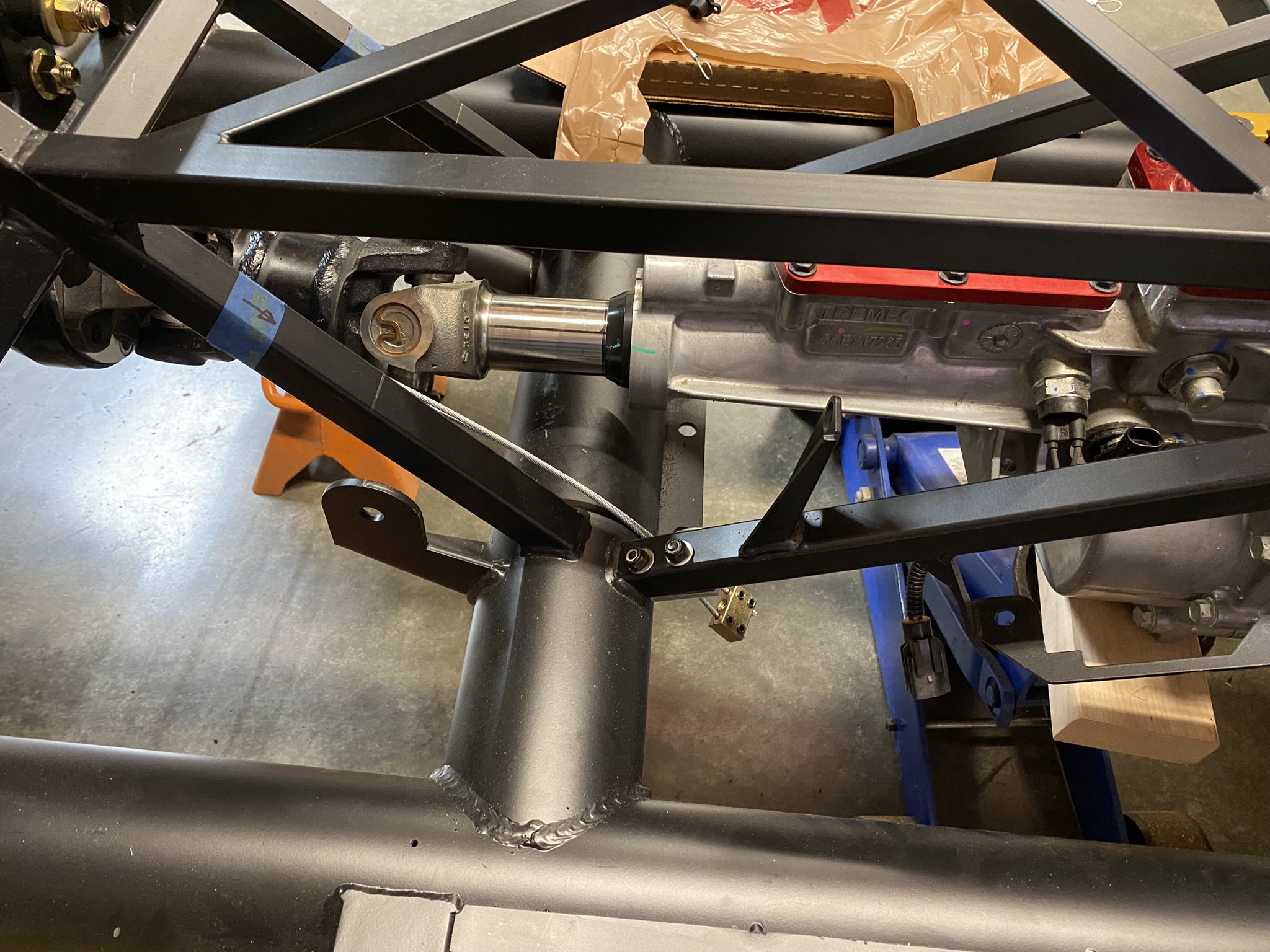
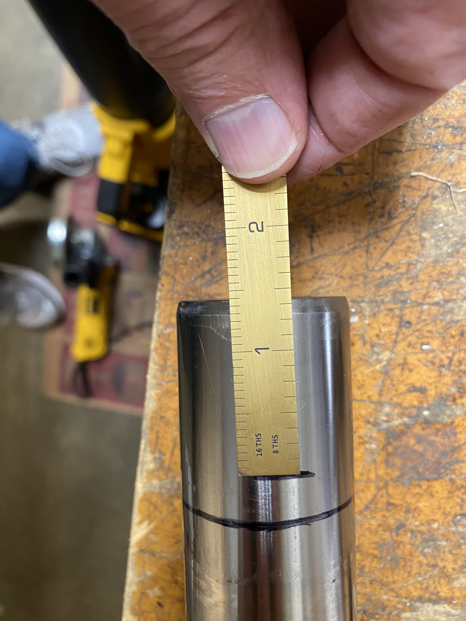
Thanks Jeff, I'll definitely measure before I drop it back in. Appreciate the heads up.
-
Originally Posted by
Its Bruce
Looks good. How do intend to plumb between the lower radiator and thermostat housing?
It shouldn't be too difficult since the radiator inlet and outlet are both on the passenger side, but those are famous last words.
-
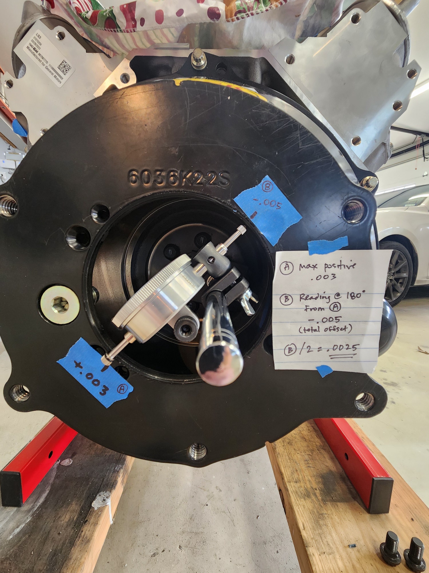
Bellhousing Alignment
Not much new to report, other than I removed the drivetrain assembly and installed the clutch and Tilton 6000 hydraulic throwout bearing. Prior to that I checked the alignment of the bellhousing and was pleased to find that I don't need any adjustments (i.e. offset dowels).
In case it helps anyone else, I used an alignment method prescribed by Silver Sport Transmissions. It's very simple and straightforward. They describe it in this video:
Using this method, I ended up with a final number of 0.0025, which is within the 0.005 tolerance required by Tremec. I believe the smallest available offset dowel 0.007, which wouldn't help here.
-
Post Thanks / Like - 1 Thanks, 1 Likes
 BRRT
BRRT liked this post
-
-
Post Thanks / Like - 0 Thanks, 2 Likes
-
-
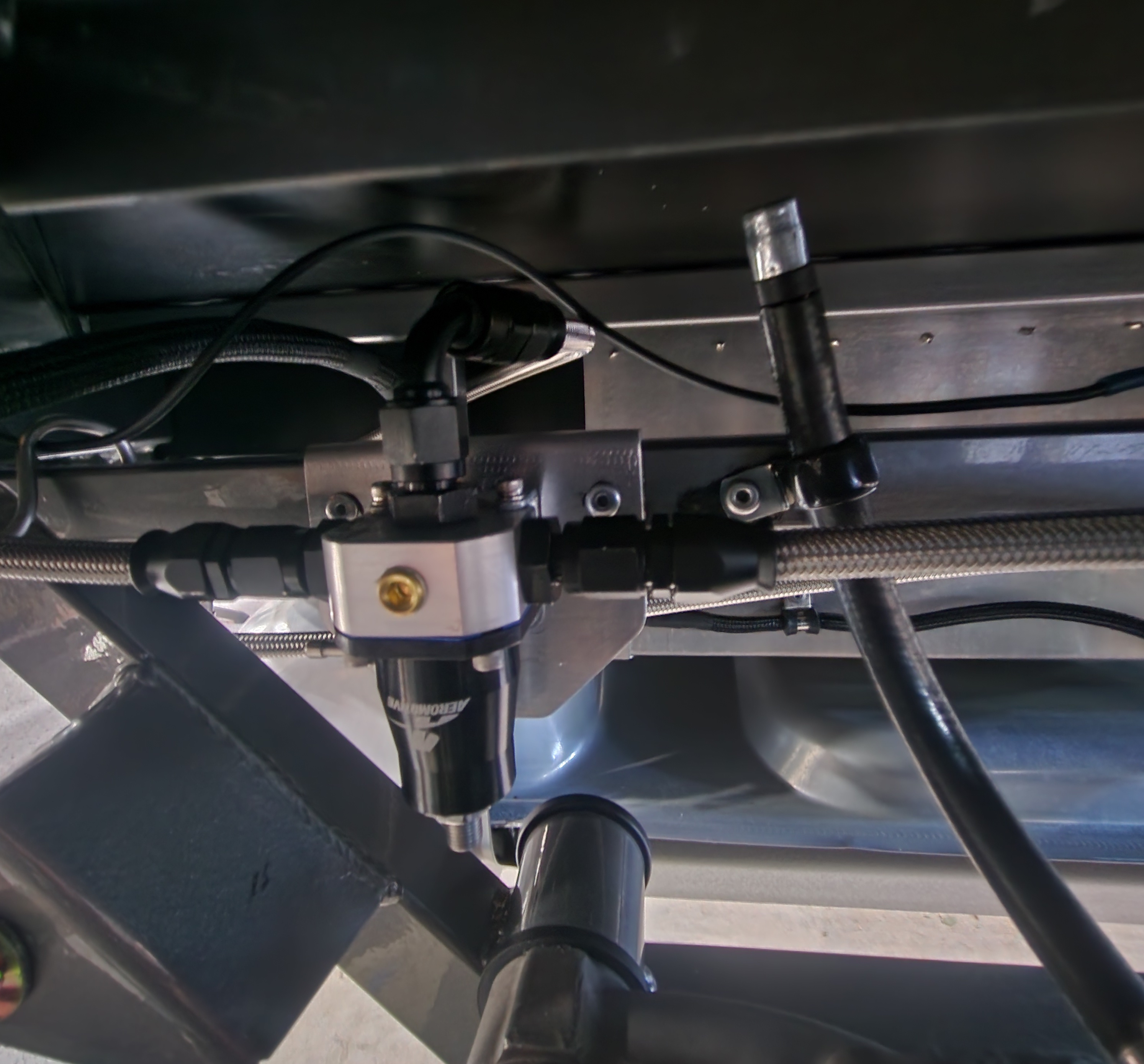
The fuel lines are all in place and pressure tested with my compressor and soapy water. Good old-school leak test. Of course I'll double check when the system is pressurized with fuel. The regulator sits just inside the passenger side rear wheel well and is very accessible.
Last edited by OB6; 04-21-2024 at 06:28 PM.
-
One thing I'll need to figure out is the connection to the lower port on the radiator. The tow loop is right there and doesn't provide much room, so I think I'll need to trim or remove it completely (maybe replace with a threaded tow hook like you'd see on many modern vehicles). Other than that, the routing is pretty straightforward.
Last edited by OB6; 04-21-2024 at 06:28 PM.
-
Wow, going on a couple months since my last update. Glad blogging isn't my day job.
The engine bay is filling up, with a lot of time spent on thinking through things like hose routing, tank placement intake design, etc. And then sourcing the parts. It's all a lot of fun, but definitely time consuming.
20240609_170954.jpg
In the most recent previous post, I mentioned how the lower radiator might be a challenge because well, this is an LS and I also have a custom radiator. I had to make a hose out of three molded hoses. Good thing the local NAPA guys are really patient didn't mind me sitting there with the catalog and asking them to retrieve certain hoses. In the end, I bought about twelve hoses and kept five to complete the upper and lower hoses. I made sure to keep the part numbers for future reference. I had to insert a 1.25" to 1.5" transition in the upper hose.
20240609_172503.jpg
20240609_172517.jpg
I went with Canton expansion and overflow tanks. I found out Canton operates an eBay store where they sell their blemished items for about 50% off in many cases.
Expansion/surge tank:
20240609_171004.jpg
Overflow tank (the bracket's will be removed and coated):
20240609_171012.jpg
The system is designed around this diagram (thanks to fellow builder Bruce for pointing me to it). I had seen it on the internet before, but not the variation without the heater.
LS cooling system - no heater_resize.jpeg
Last edited by OB6; 06-09-2024 at 05:54 PM.
-
Post Thanks / Like - 0 Thanks, 1 Likes
-
The intake took some consideration. I thought about keeping the filter in the engine bay like most people do, but GM is pretty specific about spacing requirements for the MAF sensor. Granted, plenty of people have deviated from those requirements with fine results. But I'd like to keep this in-spec as much as possible, and I'd also like to see if I can get cooler air into the engine ("cooler" is an amusing word when you live in Texas). It turns out that it's been done before with a MKIV... see this post in It's Bruce's build.
I essentially copied Bruce's setup (what's the imitation/flattery saying?) after a bunch of PM's exchanged...
20240609_155202.jpg
20240609_141309.jpg
This is just temporary hardware... no need for 1.5" bolts. 
20240609_141251.jpg
The filter will end up looking like this:
IMG-20230704-WA0005.jpg
Last edited by OB6; 06-10-2024 at 09:26 PM.
-
Post Thanks / Like - 1 Thanks, 0 Likes
-
As other LS builders have noted, the factory dipstick is not an easy fit mostly because of the engine mounts. After jacking around with it for a while, I finally decided to install a Lokar unit, which worked perfectly.
A small bend to the Lokar bracket, along with a spacer and cap screw, and it's all good:
20240609_180936.jpg
Fairly clean routing to the dipstick port:
20240609_180948.jpg
-
Senior Member

Originally Posted by
OB6
As other LS builders have noted, the factory dipstick is not an easy fit mostly because of the engine mounts. After jacking around with it for a while, I finally decided to install a Lokar unit, which worked perfectly.
A small bend to the Lokar bracket, along with a spacer and cap screw, and it's all good:
20240609_180936.jpg
Fairly clean routing to the dipstick port:
20240609_180948.jpg
That starter/motor mount/motor mount adapter/header/spark plug area sure gets crowded when it comes time to install a dipstick tube. I did something real similar after trying to bend and modify 2 GM dipstick tubes.
Yours looks real clean!
----------------------------------------------
Jeff
Roadster delivered 8/27/23
Chevrolet Performance LS3
Build Thread
-
Originally Posted by
BRRT
That starter/motor mount/motor mount adapter/header/spark plug area sure gets crowded when it comes time to install a dipstick tube. I did something real similar after trying to bend and modify 2 GM dipstick tubes.
Yours looks real clean!
Thanks Jeff - yes it's a tight area. I ruined one GM dipstick before deciding I needed to go a different route. I couldn't get a smooth enough bend that fit without the dipstick getting stuck.
-
Senior Member

MK4, 427LS3, IRS, T56 Magnum, Wilwoods
-
A quick panel for the relays and such...
20240614_112349.jpg
-
I got the air filter installed. This should work well. The rest of the intake is at the coater getting treated with cermet along with the headers.
20240621_171418.jpg
20240621_171434.jpg
-
Time for another series of procrastinated build posts. Overall, I'm getting prepared for first start. Things that need to be done before that include the following:
- Fill tank and test fuel system pressure
- Prime and fill engine with oil; will be using Driven BR30
- Install new master cylinders and bleed the hydraulics... more on that below.
- Temporarily install oil pressure and water temp gauges
- Maybe pressurize the cooling system prior to first start, or just let 'er rip and see what happens. System is filled with DexCool.
- Adjust/set the Tilton hydraulic throwout bearing. I guess this isn't really necessary for first start, but it would be nice to have it done
- Install side pipes
The engine bay is 99% done.
20240706_131111~2.jpg
I decided to have the headers ceramic metallic coated... essentially the same as JetHot.
20240703_121140.jpg
Also had the intake pipes coated the same way. The heat reduction won't provide a material benefit in this application (compared to the headers), but they look nice and match.
20240712_172720.jpg
Power steering lines are installed. I kept it simple and just routed them over the X member. Lee Power Steering was a great source for everything.
20240712_172448.jpg
I finished the gas pedal using an extra pedal pad that I ordered from Mike Forte a while back. I think it came out pretty well. The nice thing is how adjustable it is. I can move it up, down, and side to side if needed. We'll see how the current position works out and go from there.
20240711_180535.jpg
20240711_180545.jpg
20240712_171334.jpg
-
Leaking Wilwood MC
I mentioned above how I needed to install new master cylinders. I've always had this feeling that it will be "when" and not "if" one of the Wilwood MC's fails... based on nothing more than what I've read here and other forums (not necessary FFR related). I even contemplated proactively replacing all of them before I get the aluminum buttoned up, but I didn't make it a priority. Until this morning.
I started to bench bleed the clutch MC and wouldn't you know... it started leaking. I didn't get upset or annoyed... I just grabbed my wrenches, removed all three MC's and headed down to Summit Racing for new Tiltons. Sometimes it's better to just find a different solution and move on. I'm not taking it up with FFR or Wilwood... it's just not worth my time, and I have zero interest in installing a new Wilwood or rebuilding it.
20240714_154607.jpg
-
Almost ready for first start. Just tested the fuel system -- no leaks, fires, or explosions, and 58 lbs at the rail.
Just need to install the side pipes.
20240720_103026.jpg
-
First start!
Big day today with the first start of the LS3. No leaks or funny noises. All systems were operating perfectly according to the OBD2 scanner. Fans came on as they were supposed to. It really helped to have a couple friends there to check things along the way.
https://www.youtube.com/shorts/1GEP8Us2VCA
https://www.youtube.com/shorts/5xKEotfrAAs
Those are just temporary wheels and tires. I'll put rubber on the Halibrands sometime in the next few months. These work fine for now, and no worries about dinging them up.
Last edited by OB6; 08-04-2024 at 06:12 PM.
-
Post Thanks / Like - 0 Thanks, 1 Likes
-
08-04-2024, 04:07 PM
#100
Nice Job Terry! Congratulations on this milestone 
Craig C
-
Post Thanks / Like - 1 Thanks, 0 Likes
 OB6
OB6 thanked for this post
-
08-04-2024, 05:54 PM
#101
Senior Member

Great job! I've been watching your LS build and taking some pointers, although mine is for a coupe.
-
Post Thanks / Like - 1 Thanks, 0 Likes
OB6 thanked for this post
-
08-04-2024, 07:57 PM
#102
Senior Member

Congrats! That sounds just like it should!!!!!
I'm currently fitting doors, hood, and trunk. Once that's complete I'll be ready to get it licensed.
-
08-05-2024, 08:00 AM
#103
Not a waxer

Congrats Terry! I've been quietly following along because I may be venturing down a similar path soon. Thanks for the documentation!
Jeff
-
08-05-2024, 10:16 AM
#104
Originally Posted by
cc2Arider
Nice Job Terry! Congratulations on this milestone
Craig C
Originally Posted by
JimStone
Great job! I've been watching your LS build and taking some pointers, although mine is for a coupe.
Thanks guys!
Originally Posted by
Jim Frahm
Congrats! That sounds just like it should!!!!!
I'm currently fitting doors, hood, and trunk. Once that's complete I'll be ready to get it licensed.
Cool, thanks Jim. BTW, your clutch pedal stop is gold. Good luck with the body fitment... I'm not looking forward to that.
Originally Posted by
Jeff Kleiner
Congrats Terry! I've been quietly following along because I may be venturing down a similar path soon. Thanks for the documentation!
Jeff
Glad it helps Jeff. I should probably call you soon to get in your queue.
-
08-06-2024, 09:36 PM
#105
Senior Member
Sounds great  . I enjoy the oh so common "whoa, it actually started. Oh yah, I should be checking the oil pressure..."
MK4, 427LS3, IRS, T56 Magnum, Wilwoods
-
Post Thanks / Like - 0 Thanks, 1 Likes
OB6 liked this post
-
08-06-2024, 09:59 PM
#106
Originally Posted by
Its Bruce
Sounds great
. I enjoy the oh so common "whoa, it actually started. Oh yah, I should be checking the oil pressure..."
Yeah I was expecting it to crank a little longer than it did, so it took me by surprise when it came to life. It almost looked like the ignition switch shocked me. Lol
-
08-25-2024, 04:44 PM
#107
Dash
The dash is almost done. The four mounting brackets behind the dash are installed and the screws are countersunk to keep them from showing under the leather and the closed cell backing (probably 1/16 or 1/8, no more). Thanks to others before me for the idea (and especially) to John Ibele for his assistance via PM.
This process wasn't without drama. I originally attached a 0.40 backing layer to help with rigidity. Unfortunately I used 3M Super 77 which I've had great results with in the past. Unfortunately I think this Texas heat isn't conducive to proper curing, and furthermore I read that it only has heat resistance up to 150 degrees -- which could spell trouble when the dash inevitably sits in, again, the Texas heat and sun. I should have done more research before using 77. Luckily I was able to remove the backing layer without any damage to the dash. I chose to move forward without it, and only use small pieces of backing in certain places as needed (for example, between the dash and mounting brackets). I'll use panel adhesive for that.
I used a variation of the comp layout, sitting in position to make sure I could see everything well. Because of this, I decided not to place any gauges to the left of the steering wheel hub. Additionally I decided to place the clock above the grab handle... a decision that I knew would be a "love it" or "hate it" thing. I like it a lot -- IMO it gives some balance and something extra to the dash. I'm sure many will disagree.
The only other items I'll add to the face of the dash are the e-brake button (probably to the left of the steering hub), a couple billet push-button switches for high-beams and interior lights, and the check-engine light. I want to keep it as clean as possible. The hazard switch is built into i.e.427's turn signal switch. The switches for headlights, ignition, and wipers will all go under the dash in the panels I built.

-
08-26-2024, 07:06 AM
#108
Looks good Terry! I like that you are making your own special customizations
What's the part number for your grab handle?
Craig C
-
08-26-2024, 07:55 AM
#109
Senior Member

Originally Posted by
OB6
The dash is almost done. The four mounting brackets behind the dash are installed and the screws are countersunk to keep them from showing under the leather and the closed cell backing (probably 1/16 or 1/8, no more). Thanks to others before me for the idea (and especially) to
John Ibele for his assistance via PM.
This process wasn't without drama. I originally attached a 0.40 backing layer to help with rigidity. Unfortunately I used 3M Super 77 which I've had great results with in the past. Unfortunately I think this Texas heat isn't conducive to proper curing, and furthermore I read that it only has heat resistance up to 150 degrees -- which could spell trouble when the dash inevitably sits in, again, the Texas heat and sun. I should have done more research before using 77. Luckily I was able to remove the backing layer without any damage to the dash. I chose to move forward without it, and only use small pieces of backing in certain places as needed (for example, between the dash and mounting brackets). I'll use panel adhesive for that.
I used a variation of the comp layout, sitting in position to make sure I could see everything well. Because of this, I decided not to place any gauges to the left of the steering wheel hub. Additionally I decided to place the clock above the grab handle... a decision that I knew would be a "love it" or "hate it" thing. I like it a lot -- IMO it gives some balance and something extra to the dash. I'm sure many will disagree.
The only other items I'll add to the face of the dash are the e-brake button (probably to the left of the steering hub), a couple billet push-button switches for high-beams and interior lights, and the check-engine light. I want to keep it as clean as possible. The hazard switch is built into i.e.427's turn signal switch. The switches for headlights, ignition, and wipers will all go under the dash in the panels I built.
I like it.
I too wanted something on the PS dash to break up the blank space, especially since I wasn't having a glove box there.
I think Shelby himself put the speedo on the PS dash to piss off race officials who required a speedo in a race car.30B1875D-81E2-42B0-B2A7-12C3394E6915.jpg
-
08-26-2024, 08:51 AM
#110
Originally Posted by
cc2Arider
Looks good Terry! I like that you are making your own special customizations
What's the part number for your grab handle?
Craig C
Thanks Craig. It's a 12" stainless handrail from West Marine, model # 12868733.
-
08-26-2024, 08:52 AM
#111
Originally Posted by
egchewy79
I like it.
I too wanted something on the PS dash to break up the blank space, especially since I wasn't having a glove box there.
I think Shelby himself put the speedo on the PS dash to piss off race officials who required a speedo in a race car.
30B1875D-81E2-42B0-B2A7-12C3394E6915.jpg
Thanks - I really like your dash... the layout and the color. Yes, that would seem to fit Shelby's personality.


 Thanks:
  Likes:


 Reply With Quote