-
11-06-2023, 01:15 PM
#161
Senior Member

One more question on power --> Originally I planned to run an 8AWG +12V feed from the switched side of master disconnect over to the Blue Seas terminal block behind the dash. Would there be any concern if I ran a 4AWG instead? I might add a 2nd fuse panel with 6 additional circuits behind the dash, and I was thinking the 4AWG would be safer to power both the RF fuse panel and the new fuse panel daisy chained off the Blue Seas terminal block. Any concerns with this? The Blue Seas terminal block can handle plenty of current (100 amp) so I'm not concerned with that part - just wondering if there is any downside of running the 4AWG cable which I already have plenty of from the FFR kit. I'd need to buy some 8AWG wire, so there's that too (but that's a minor issue).
Darryl [dbo_texas]
MKIV #9644 (build thread) (Index)
MK4 Complete Kit | Gen2 crate Coyote | Tremec T56, 3.55 IRS | power steering | hydroboost | dual roll bars | FFR carbon fiber dash | 18" Halibrands + Wilwoods | RT drop trunk kit & turn signal | front battery mount | saddle leather Intatrim Stoneleigh seats + interior accents
-
12-04-2023, 10:06 AM
#162
Senior Member
#9644 updates - dash and power wiring
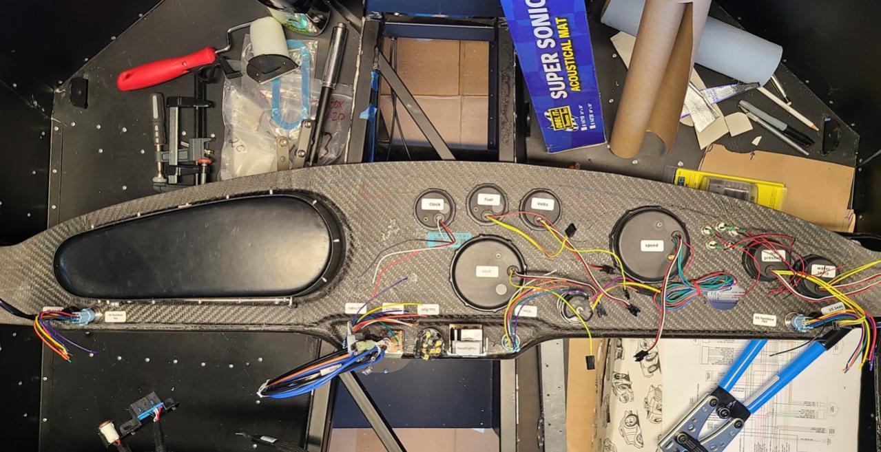
It's been a little while since I updated, but I've been slowly working through the electrical. My primary goal is to finish the power wiring and re-routing the Coyote harness starter wire and main harness ground to run with the power from the master disconnect to the starter location. All this has to be completed so I can re-install the drivetrain. As of last night, I finally finished those items, as well as finished mounting all the switches & knobs on the CF dash. I haven't completed the dash yet (i.e. haven't daisy chained the gauges or attached the dash harness), but it feels good to get all the switches mounted.
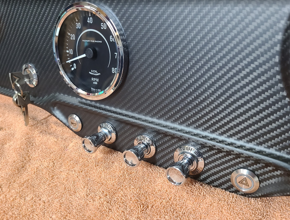
Here's the dash - I'll post more about this later along with a full breakdown of some of the modifications I had to do, but the main item is that I now have all the '65 Mustang switches mounted. I ended up sticking with the stock FFR headlight switch instead of the '65 mustang headlight switch, and I was able to modify the shaft and Mustang knob so it works (maintains 65 mustang knob appearance). But I am still using the '65 Mustang wiper knob (rotary), and heater knob (w/ FFR heater kit switch).
I got the battery installed (Optima Yellow Top 8071-167) - it's a Group D51 size and installed in the front mount location with the Breeze box. No issues with that:
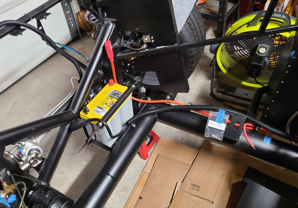
For the power wiring, I followed edward's 20th anniversary build, as many others have done. I also switched to #2 AWG battery cables with a #4 going to the starter. I de-loomed the ECU leg of the Coyote harness so that I could pull out the blue starter wire and rout that down with the battery cables to where it needs to end up on the passenger side near the engine mount. I also ran the Coyote harness blunt-cut #10 AWG ground wire with these items and ran it all the way up to the front battery ground location. Finally, I ran a wire through the Coyote ECU leg that I can tie into the Coyote Cooling Fan wire (orange) and ran that back up the loom into the dash so I can run it to my dash indicator light which will show me when the fan is running.
Here's the Coyote ECU leg after pulling it out of the 1" split loom:

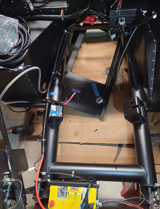
This is what it looks like as I was re-adjusting the wiring. The blue wire running with the power cables is the starter wire (from Coyote ECU leg) - it terminates near the PS engine mount along with the starter +12V switched from the Master Disconnect. The blue wire hanging down is the fan wire running back to the dash for the indicator light (I didn't have any orange wire so just used what I had). All I can say is that my fingers are numb from getting these cables out of the loom and peeling off all that damn tape.

And here it is all buttoned up and put back into the split-loom. I may re-wrap these with some cloth loom tape and I also need to buy some smaller cable clamps. I bought the 1.125" ones from DelCity but they are way too big...I think I need the 1" or maybe even one size smaller than that (7/8" looks like it would be the best but I haven't found any that size yet). 3/4" looks like it would be too small:
Darryl [dbo_texas]
MKIV #9644 (build thread) (Index)
MK4 Complete Kit | Gen2 crate Coyote | Tremec T56, 3.55 IRS | power steering | hydroboost | dual roll bars | FFR carbon fiber dash | 18" Halibrands + Wilwoods | RT drop trunk kit & turn signal | front battery mount | saddle leather Intatrim Stoneleigh seats + interior accents
-
Post Thanks / Like - 1 Thanks, 1 Likes
-
12-04-2023, 01:13 PM
#163
25th Anniversary #9772


Originally Posted by
dbo_texas

Here's the dash - I'll post more about this later along with a full breakdown of some of the modifications I had to do, but the main item is that I now have all the '65 Mustang switches mounted. I ended up sticking with the stock FFR headlight switch instead of the '65 mustang headlight switch, and I was able to modify the shaft and Mustang knob so it works (maintains 65 mustang knob appearance). But I am still using the '65 Mustang wiper knob (rotary), and heater knob (w/ FFR heater kit switch).
I got the battery installed (Optima Yellow Top 8071-167) - it's a Group D51 size and installed in the front mount location with the Breeze box. No issues with that:
love that dash setup! very nice!
-
12-04-2023, 03:33 PM
#164
Senior Member
Thanks - I got the inspiration from Lidodrip and a few others who've used the 65 mustang switches/knobs/bezels. They really look clean on this dash. Now I just need to figure out how to wire everything up!
Darryl [dbo_texas]
MKIV #9644 (build thread) (Index)
MK4 Complete Kit | Gen2 crate Coyote | Tremec T56, 3.55 IRS | power steering | hydroboost | dual roll bars | FFR carbon fiber dash | 18" Halibrands + Wilwoods | RT drop trunk kit & turn signal | front battery mount | saddle leather Intatrim Stoneleigh seats + interior accents
-
Post Thanks / Like - 0 Thanks, 1 Likes
-
12-29-2023, 12:12 PM
#165
Senior Member
T56 Reverse Light & Reverse Lockout wiring questions
I'm routing my rear harness, and I'd like to add some wires for a reverse light and reverse lockout.
For the reverse light:
I plan to use the reverse light function on my T56 transmission and already have the connector on the transmission (2-pin weather pack on the PS of near the front). Do I run +12V on ignition to one lead on the T56 reverse light connector, and then the other lead from that connector goes to the light in the back of the car? Then I would just attach the ground lead of the actual light to chassis ground? Is that the proper way to wire this?
The idea is that when you put the transmission into reverse, the reverse switch (on transmission) will close the circuit for +12V going to the reverse light. Just looking for confirmation before I add in my extra wires to the rear harness (will need to break out 2 wires ends in the area near the transmission connector).
For the reverse lockout:
I bought the reverse lockout from Forte's --> I need to see what needs to be routed for that connection as well (haven't researched it yet). I think there is a module (maybe a GPS? or maybe uses the speed sensor?) that I need to mount behind the dash, then run the connection up the trans tunnel to the dash. If anyone has bought/used the one from Mike Forte and can share details on how this works (i.e. the logic), please share! I will also go read the instructions that came with it  Probably a good starting point.
Darryl [dbo_texas]
MKIV #9644 (build thread) (Index)
MK4 Complete Kit | Gen2 crate Coyote | Tremec T56, 3.55 IRS | power steering | hydroboost | dual roll bars | FFR carbon fiber dash | 18" Halibrands + Wilwoods | RT drop trunk kit & turn signal | front battery mount | saddle leather Intatrim Stoneleigh seats + interior accents
-
12-29-2023, 03:04 PM
#166
Senior Member

It's just a NO switch, so 12V or ground will be enough to engage the reverse light(s).
MK4, 427LS3, IRS, T56 Magnum, Wilwoods
-
Post Thanks / Like - 1 Thanks, 0 Likes
-
12-29-2023, 05:51 PM
#167
Senior Member
Originally Posted by
Its Bruce
It's just a NO switch, so 12V or ground will be enough to engage the reverse light(s).
OK perfect thanks that's what I thought. I think I'll bring 12V ignition power to the switch, then ground it at the light in the back of the car.
Darryl [dbo_texas]
MKIV #9644 (build thread) (Index)
MK4 Complete Kit | Gen2 crate Coyote | Tremec T56, 3.55 IRS | power steering | hydroboost | dual roll bars | FFR carbon fiber dash | 18" Halibrands + Wilwoods | RT drop trunk kit & turn signal | front battery mount | saddle leather Intatrim Stoneleigh seats + interior accents
-
12-29-2023, 05:57 PM
#168
Senior Member
Originally Posted by
dbo_texas
I'm routing my rear harness, and I'd like to add some wires for a reverse light and reverse lockout.
For the reverse light:
I plan to use the reverse light function on my T56 transmission and already have the connector on the transmission (2-pin weather pack on the PS of near the front). Do I run +12V on ignition to one lead on the T56 reverse light connector, and then the other lead from that connector goes to the light in the back of the car? Then I would just attach the ground lead of the actual light to chassis ground? Is that the proper way to wire this?
The idea is that when you put the transmission into reverse, the reverse switch (on transmission) will close the circuit for +12V going to the reverse light. Just looking for confirmation before I add in my extra wires to the rear harness (will need to break out 2 wires ends in the area near the transmission connector).
For the reverse lockout:
I bought the reverse lockout from Forte's --> I need to see what needs to be routed for that connection as well (haven't researched it yet). I think there is a module (maybe a GPS? or maybe uses the speed sensor?) that I need to mount behind the dash, then run the connection up the trans tunnel to the dash. If anyone has bought/used the one from Mike Forte and can share details on how this works (i.e. the logic), please share! I will also go read the instructions that came with it
Probably a good starting point.
OK I think for the reverse lockout, after looking at the instructions, I just need to route 4 wires from the module behind the dash to the connectors on the transmission. One pair of wires to the lockout solenoid, and one pair to the VSS (speed sensor). I'm not using the speed sensor on the trans since I'm using the vintage gps speedo. So that should work out fine. There are also +12v ignition power and ground connections on the module that I'll connect behind the dash.
Darryl [dbo_texas]
MKIV #9644 (build thread) (Index)
MK4 Complete Kit | Gen2 crate Coyote | Tremec T56, 3.55 IRS | power steering | hydroboost | dual roll bars | FFR carbon fiber dash | 18" Halibrands + Wilwoods | RT drop trunk kit & turn signal | front battery mount | saddle leather Intatrim Stoneleigh seats + interior accents
-
Post Thanks / Like - 0 Thanks, 1 Likes
-
02-05-2024, 10:36 PM
#169
Senior Member
Drivetrain Install - Part 1 (engine & trans prep and install)
At this point I've spent the last couple of months working on the electrical. I'll do a few separate posts later once the electrical is completely finished, but for now I've modified all the harnesses and installed them in the car. I've also installed all the Coyote specific harnesses & ECU. This was the gating item preventing me from reinstalling the drivetrain, so with that out of the way, it was time to re-install. I prepped the engine bay by disconnecting the steering shaft to get it out of the way. I also disconnected my front brake hard lines where they mount to the F-panels. I might have been OK leaving them in place, but since I haven't bled the brakes yet I just disconnected them to push them out of the way. I then removed the battery from the Breeze box. I probably could have left it, but again, it was easy to remove and get it out of the way. Once I lifted the engine off of the FFR Coyote stand, I also did a quick test fit of both headers to make sure the bolt holes all lined up, and thankfully they did.
Prepping the transmission mount: I had a hell of a time finding the correct fasteners, and found that whoever installed the mount the first time used the wrong size fasteners. Looks like they used 7/16-14 bolts instead of the correct sized 1/2-13 bolts. Some of the threads were damaged, so I re-tapped both holes and then installed with the correct size bolts --> everything snugged up well so I think I'm good with the fasteners. I also removed the shifter assembly to make it easier to install into the frame.

Question: For those with my same combination (Coyote + T56), did you end up using the spacers with the trans mount? The FFR Coyote Fitment instructions don't show them, but the FFR Complete Kit instructions do show them. I'm not sure which one is correct for the Coyote + T56. I didn't install them, but I also ended up with a pretty big 1/2" gap between the trans mount and the A-frame after installing the engine. More questions on this later...

A-Frame Install: Also couldn't find these fasteners so went digging around in my parts bin and found the correct sized bolts and nuts. Install was no problem --> I installed it on TOP of the FFR frame tabs, but I've seen some folks say it may work better mounted below the tabs. So I may need to swap this - I need to study this more and figure out which will work best with my combo.

Engine Prep: Some of the work was already done by Forte, like the oil pan and oil filter nipple. The only think I really had to do was install the Vintage Gauge oil pressure sender and water temp sender. Had to dig around for quite a while to find the correct brass adapters, but ultimately got them both installed without too much trouble. I used Permatex high-temp thread sealant instead of Teflon tape (per FFR instructions) on the NPT threads for both.
Question: for the oil sender plug coming from the engine harness, will this be used at all or can it just get tucked away somewhere and secured?

Coyote Engine Mount Spacers: These 1/2" spacers come with the Coyote Install kit from FFR. No real issues with this, other than again having to dig around to find the correct fasteners (notice a trend here?). Overall, no problem with installing these per the instructions.

Drivetrain Install: We used a 2-ton hoist with a leveler and extended the boom all the way out (on the 1/2 Ton setting). This allowed us to come in from the front. We had the back of the frame lifted on jacks, and the front end was sitting on tire dollies to lower it a little bit. This helped with getting the transmission over the radiator 3/4" frame bar at the front. From here, it was just a lot of small movements - one person to steer the transmission, one person to steer the hoist, and one person keeping an eye on clearances all around.

At this point the engine was about 2" above the mounts. So it was time to install the headers while you still have some amount of access.

Last edited by dbo_texas; 02-05-2024 at 11:38 PM.
Darryl [dbo_texas]
MKIV #9644 (build thread) (Index)
MK4 Complete Kit | Gen2 crate Coyote | Tremec T56, 3.55 IRS | power steering | hydroboost | dual roll bars | FFR carbon fiber dash | 18" Halibrands + Wilwoods | RT drop trunk kit & turn signal | front battery mount | saddle leather Intatrim Stoneleigh seats + interior accents
-
02-05-2024, 11:34 PM
#170
Senior Member
Drivetrain Install - Part 2 (Headers Install, Driveshaft IRS adapter, driveshaft)
I have the FFR Coyote Full Length stainless steel headers (p/n 16267). I've read that it's best to install these onto the engine when you are about 2-3 inches from seating the engine on the mounts. So with the engine/trans mostly installed, we gave it a go. The gaskets that came with the headers were folded in half in the box - not sure how that happened, but I didn't want to risk the crease causing any issues so I bought some new gaskets. We'll call it a $35 piece of mind purchase. I ended up going with some Remflex #3609 header gaskets as many others have used.
We started with the driver's side header. Before we installed the engine, I removed all 16 of the header studs that came installed on the engine. I decided to use all bolts instead, and I measured the thread size on the studs to be M10x1.5. To install the header, one person held the gasket in place, while a 2nd person placed the header over it and then got all the bolts started. For the bolts, I replaced the bolts provided by FFR and went with the Stage 8 #8914 locking bolts. These are great because they have a locking tab that you butt against the header tube, and then an little clip to hold it in place. This prevents the bolt from rotating counter-clockwise and loosening. Since these have locking hardware, I didn't use any Loctite but instead opted to use some anti-seize on them. Not sure if that was needed or not, but I don't think it could hurt to prevent some headaches in the future if I ever have to remove the bolts.

Here you can see a closeup of the Stage 8 header bolt with the locking tab and clip.
Let me just say that I hope to God I did this correctly, because I don't ever want to have to remove and reinstall these headers. What a pain to install. On the DS especially, accessing the bolts is extremely difficult. I used everything in the toolbox (universal joint sockets, box end wrenches, extensions, etc). The FFR instructions do not give any recommendation on torque, so after doing some searching on this forum I found several recommendations to go with something in the 18-24 ft-lb range. I decided to go with 22 ft-lb. On the DS I could really only use the torque wrench on maybe 3 or 4 of the bolts, and on the PS probably 6 of them. For all the others, I used my finely calibrated hands to gauge how much to tighten them based on the ones I could access. Anyhow, I got them all installed. The PS was way easier to do vs. the driver side. All the bolts are more easily accessible on that side.
With the headers installed, I wanted to install the driveshaft IRS adapter and driveshaft. Once again, I had to go hunting for the correct bolts because they weren't with my adapter. After some digging, I ended up finding the correct bolts. They are socket head cap screws, size M10x25. I read on the forum that some 4 should be M10x20, and 6 should be M10x25, but all 10 of mine were M10x25 and they seem to work. The adapter uses 6 of these bolts going into the counterbore holes on the adapter and threading into the IRS joint. The remaining 4 are used to secure the driveshaft to the adapter. My adapter was the clear-zinc plated version, not the yellow-zinc one. I inserted the driveshaft before making the final engine push and this allowed me to get all the bolts installed. I didn't get any pictures of just the adapter installed on the IRS pumpkin, but the install was pretty straight forward. I torqued the bolts down per FFR instructions and applied some blue Loctite.
The driveshaft I have is FFR p/n 16038 (ROADSTER 31 SPLINE 8.375" DRIVESHAFT FOR 2015 IRS) which I'm pretty sure is the correct one for the Coyote + T56. After installing, it looks like this:

With both headers+gaskets on, and the driveshaft adapter and driveshaft installed, I went ahead and dropped the engine onto the mounts. This last 2 or 3 inches was quite difficult and I had to keep readjusting the transmission. I was finally able to get the mounting studs through the engine mount slots on both sides of the frame. Here's how both sides sit in the engine mounts:
Driver's side mount --> the stud is sitting about .375" above the bottom of the slot in the mount. Question: Does this look correct?

Here's the passenger side mount. It is seated at the bottom of the slot.

There are a few items I don't think look correct with my transmission mount and possibly the driveshaft, but I'll ask some questions about those in the next post. I haven't looked at the pinion angle or driveshaft angles yet --> I need to do some more research on what this should look like. As it stands, the driveshaft is pretty much straight between the pumpkin and trans and I know that isn't correct. So something is off.
Despite the issues w/ the transmission mount (to be detailed in future post), this still feels like a big accomplishment. With the engine back in, I think I can start reassembling a ton of items (radiator, hood hinges, coolant expansion tank, reservoirs, etc). Here's the final result:


Darryl [dbo_texas]
MKIV #9644 (build thread) (Index)
MK4 Complete Kit | Gen2 crate Coyote | Tremec T56, 3.55 IRS | power steering | hydroboost | dual roll bars | FFR carbon fiber dash | 18" Halibrands + Wilwoods | RT drop trunk kit & turn signal | front battery mount | saddle leather Intatrim Stoneleigh seats + interior accents
-
02-06-2024, 12:56 PM
#171
Senior Member
T56 interference, A-frame Modification, Transmission Mount, Driveshaft Installation
When I installed the drivetrain I found that I couldn't get the transmission mount to sit down on the A-frame. After some back and forth troubleshooting (detailed in THIS THREAD), here is a summary of what I found and how I fixed it.
1) T56 & A-Frame Interference & Fix:
It turns out the T56 transmission body was hitting the A-Frame, preventing it from seating all the way down on the transmission poly mount. After contacting FFR & some suggestions by Mike Everson, I determined that sometime after my kit was built (2019), FFR changed the A-frame design and shortened the plate spanning the two legs on the A-frame. You can see it very clearly here - my setup on the left (showing the T56 hitting the A-frame plate), and on the right is a picture FFR sent me of their current A-frame. I think Mike Everson said the A-frame was modified around the time The Tremec TKX came out.

I'm not sure exactly how much they shortened it but it looks to be about 1.5-2" (using the FFR "5" logo as a gauge). I could have bought a new A-frame ($255+shipping), but instead I decided to modify my A-frame. I cut away 2" from the plate, then with the help of a neighbor we re-welded a strengthening flange back onto it. The flange was made from the piece we trimmed off the plate. This resolved the interference issue and allows the transmission to fully seat down onto the A-frame, all while retaining plenty of strength. Read the post linked above for details on the modification to the A-frame, but this is the result:

2) Driveline/Pinion Angles
Next up was the driveline angles. Based on THIS POST and THIS POST, the 3 general criteria when setting up the driveline angles are:
- Ideally, the pinion angle should be 1 degree or less
- The operating angles on each end of the driveshaft should be equal to or within 1 degree of each other and have a 3 degree maximum operating angle
- Have at least 1/2 of a degree continuous operating angle. Some definitions…
After fixing the A-frame and getting the transmission seated on the A-frame, I took measurements and found that while my pinion angle looked good, my two operating angles exceeded the 3° recommended angles. This is all captured in the A-frame post HERE. To resolve this, I ended up removing the 0.4" cylindrical spacers and washers that FFR includes with the transmission mounting hardware. After removing them, I now meet all 3 criteria above for the driveline angles. Here are the resulting numbers with some reference images of how/where I took my angle measurements. I'm happy with these so I'm calling it good:
Measurements:
- Frame: 0deg (reference)
- Engine/Trans: -1.1° sloping down toward the rear
- Driveshaft: -1.85° sloping down toward the rear
- IRS pinion flange: -0.75° sloping down toward the rear
- OA1 = 0.75°
- OA2 = 1.1°
- Pinion Angle = 0.35°

Last edited by dbo_texas; 02-23-2024 at 11:31 AM.
Reason: Updated with details of A-frame fix and pinion angle
Darryl [dbo_texas]
MKIV #9644 (build thread) (Index)
MK4 Complete Kit | Gen2 crate Coyote | Tremec T56, 3.55 IRS | power steering | hydroboost | dual roll bars | FFR carbon fiber dash | 18" Halibrands + Wilwoods | RT drop trunk kit & turn signal | front battery mount | saddle leather Intatrim Stoneleigh seats + interior accents
-
02-25-2024, 09:16 PM
#172
Senior Member
-
04-08-2024, 10:59 AM
#173
Senior Member
Safety Loop Modification, Engine Lift Brackets, Triple Reservoir
Got a few hours of work in over the weekend.
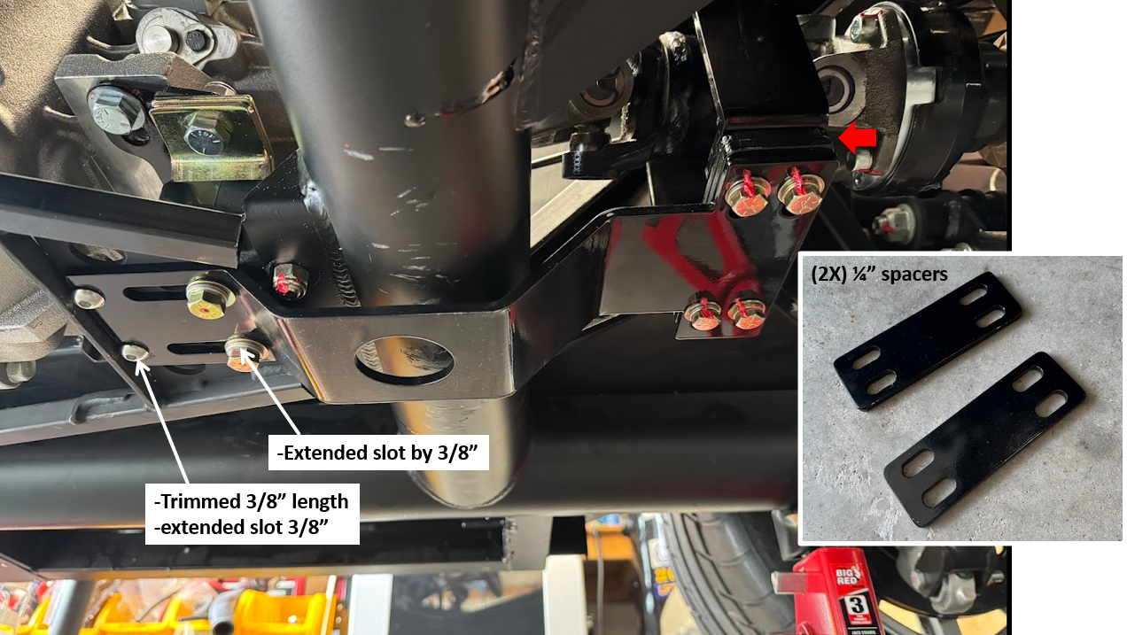
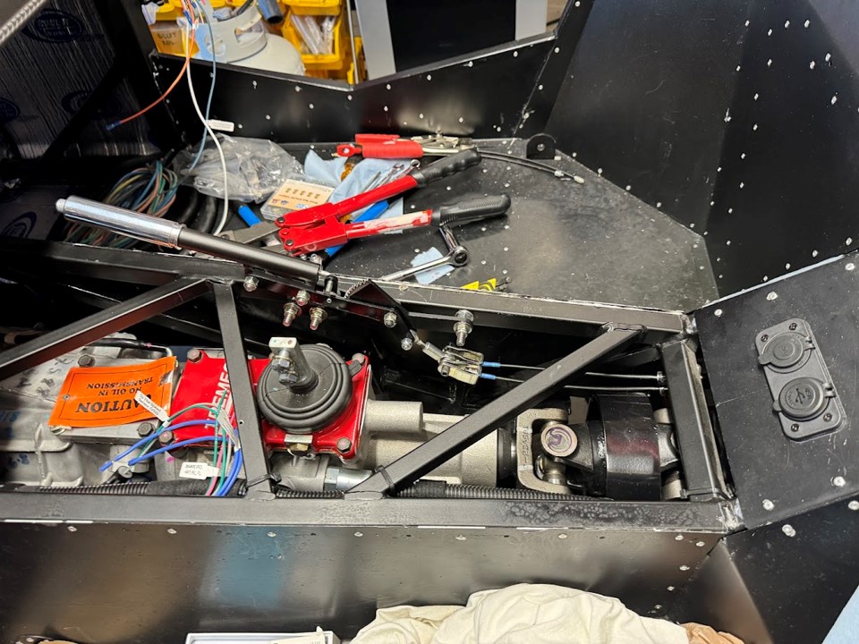
Safety Loop Modification
After the initial fitment, there were 2 changes I wanted to make. For the first, I wanted to shift the loop towards the front by about 3/8 inch to provide a little more clearance to the U-joint knuckles. To accomplish this, I needed to trim the front edge and elongate the mounting slots for the bolts. Used my angle grinder with cutoff wheel to make the long cut, then drilled new holes to extend the slots and used a Dremel cutoff wheel to clean up the slots. For the second update, I wanted to replace the washers I was using as spacers for the hoop with some solid aluminum spacers. I modeled these up in CAD then cut them on a laser cutter then painted them w/ epoxy paint. They turned out great and were a perfect fit.
Engine Lift Bracket Removal
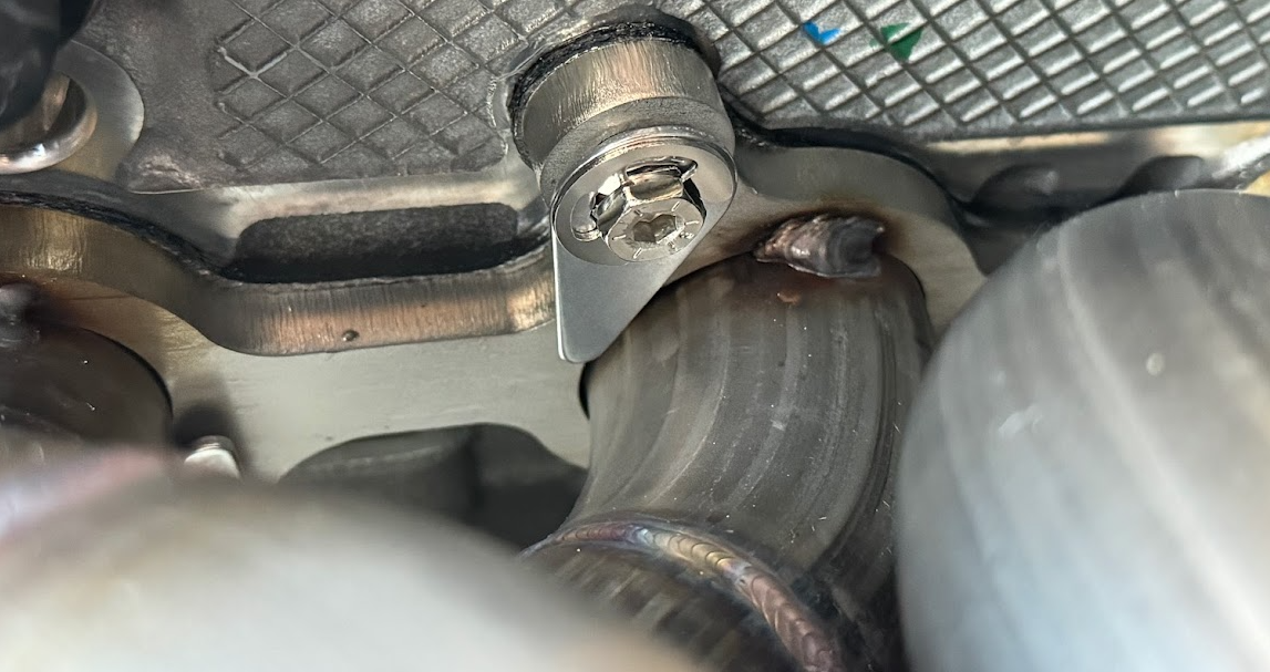
Next up was to remove the Coyote lift brackets. This is where I ran into some trouble. I had read on another member's forum post that they ran into a problem removing one of the bolts --> there wasn't enough clearance to the Coyote header tube to back the bolt out. Well I ran into the same problem...I was aware of this but I didn't see the post until I already had the header installed and the engine in place.
The only way to cut this was with a multi-tool, but unfortunately for my build the hydroboost and steering shaft were in the way and I couldn't get the tool in. So I removed the steering shaft and unbolted the master cylinder from the front of the hydroboost, and this just barely gave me enough access to get the multitool in there.

I must have used some high strength alloy bolts because I chewed through (2x) nitrous carbide multi
-tool bits ($35) cutting the bolt, but I finally go it.

Oil Filter Install
With the engine lift brackets removed, I went ahead and installed the low profile oil filter. I used Fram PH10060, but Mobil M1-113 or STP S10060 would also work from what I've read.

Triple Reservoir Re-Install
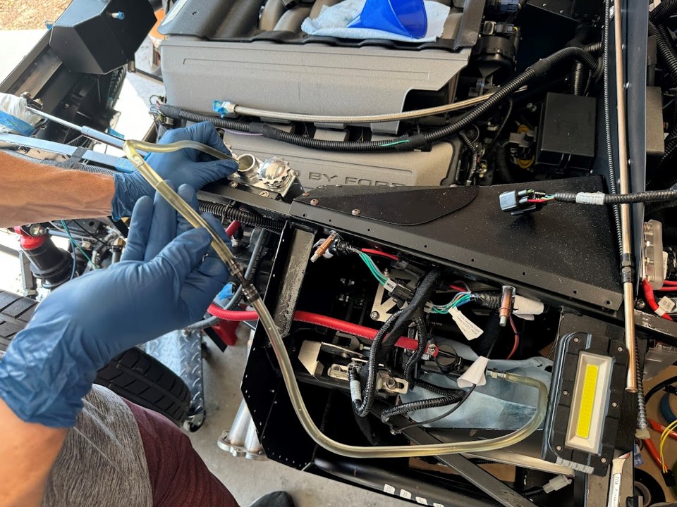
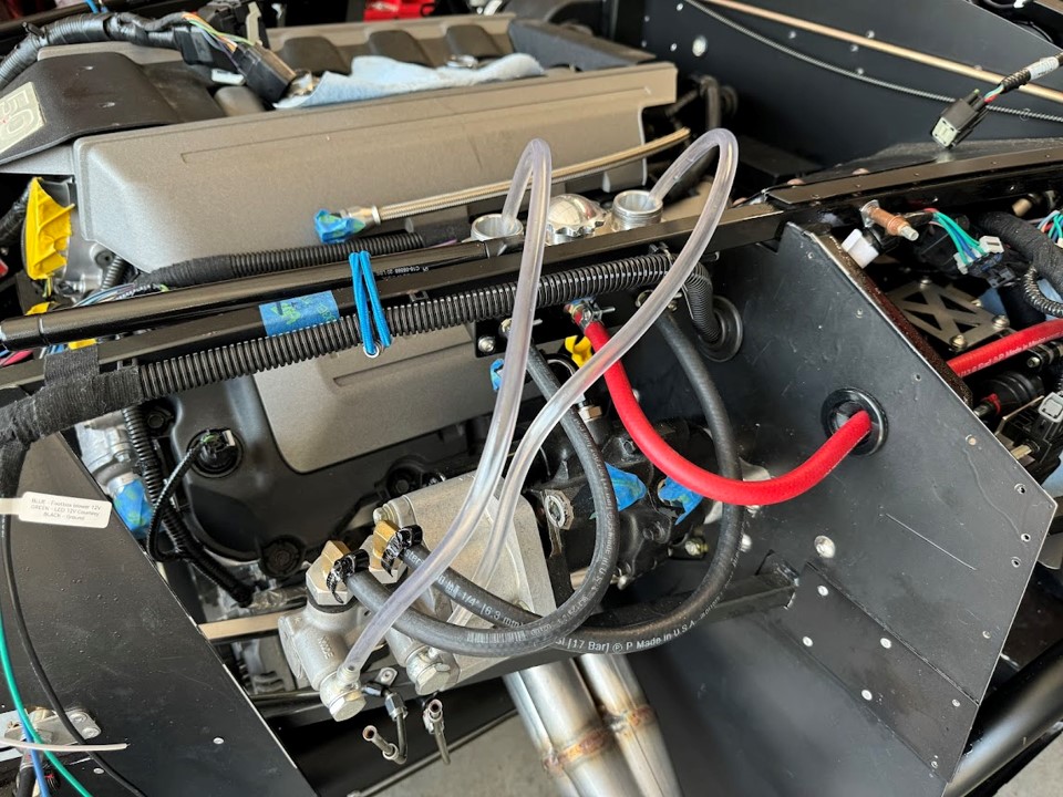
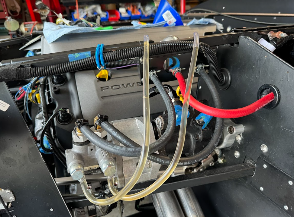
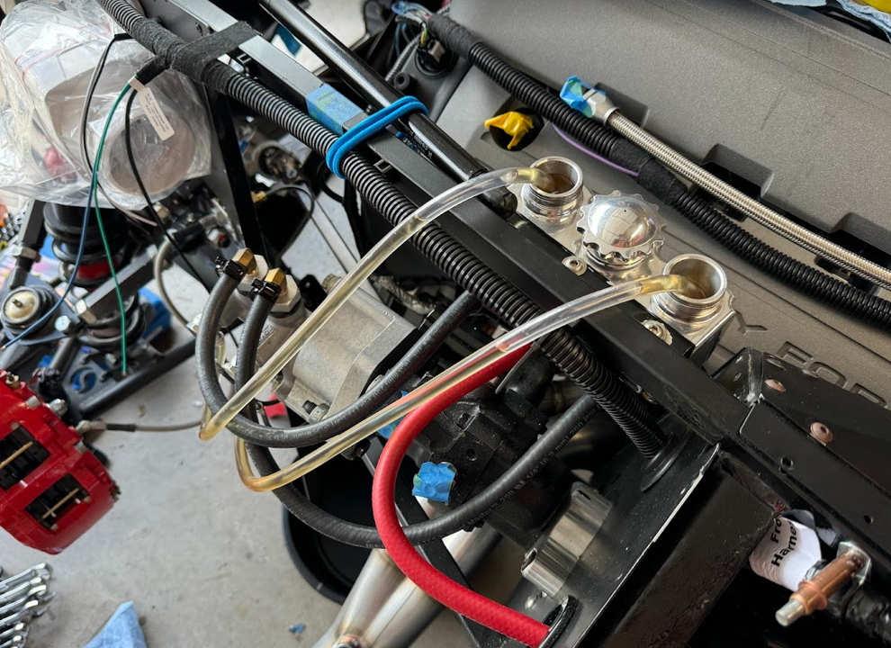
With the engine installed, I went ahead and reconnected my front brake lines and re-installed the triple reservoir. I had already made the mounting brackets and drilled the holes, so all I had to do was rivet the bracket onto the 3/4" frame and mount the hoses w/ hose clamps. Red hose goes to clutch, and the two black hoses go to the brakes.


Darryl [dbo_texas]
MKIV #9644 (build thread) (Index)
MK4 Complete Kit | Gen2 crate Coyote | Tremec T56, 3.55 IRS | power steering | hydroboost | dual roll bars | FFR carbon fiber dash | 18" Halibrands + Wilwoods | RT drop trunk kit & turn signal | front battery mount | saddle leather Intatrim Stoneleigh seats + interior accents
-
04-21-2024, 09:00 PM
#174
Senior Member
Re-mount radiator, hood hinges, expansion tank, Coyote PCM
I had a few hours of free time Saturday so decided to re-mount a bunch of the accessories. First thing I did was tighten the engine mount nuts to 60 ft-lbs. I couldn't find a spec for this but some folks on the FB page provided some recommendations in the 55-65 ft-lb range, so I split the difference.
Next up, I re-mounted the radiator. This went super quick since I was already familiar with how it mounts. I zeroed my angle finder on the bottom 4in frame tube, then taped it to the radiator and mounted it at the recommended 51°. While I was at it I went ahead and riveted the Breeze upper radiator mount hinge to the radiator. I had previously left that unmounted because I was on the fence about painting the radiator black. Since I'm not going with the chrome delete aesthetic any more, I went ahead and left the radiator as-is (unpainted). Here's the result:
Next up was the hood hinges. These also went on very quickly since I've mounted them previously. I left the nuts just barely tight because I know I'll need to adjust them when it comes time to fit the hood. For now the gas struts are just tied to the 3/4 frame tubes.

After this, I re-mounted the Mishimoto coolant expansion tank. 3 screws to mount it, and done.

I really like the sight tube on the side of this tank.
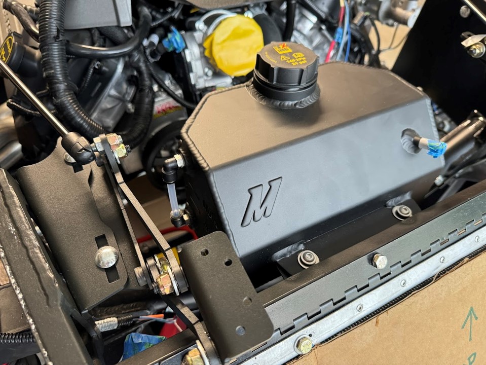
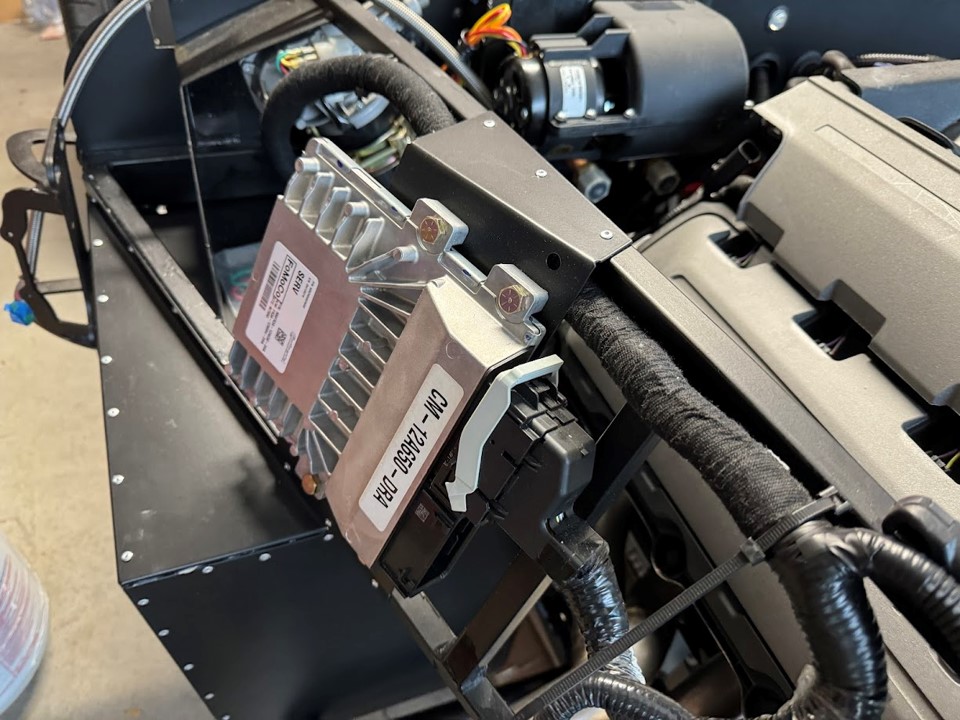
After this, I went ahead and riveted down the Coyote PCM mounting bracket to the 3/4" frame tubes. I had been holding this on with clecos but I see no reason not to go ahead and mount it.
NEXT STEP: trans tunnel shifter hole
Darryl [dbo_texas]
MKIV #9644 (build thread) (Index)
MK4 Complete Kit | Gen2 crate Coyote | Tremec T56, 3.55 IRS | power steering | hydroboost | dual roll bars | FFR carbon fiber dash | 18" Halibrands + Wilwoods | RT drop trunk kit & turn signal | front battery mount | saddle leather Intatrim Stoneleigh seats + interior accents
-
04-21-2024, 09:46 PM
#175
Senior Member
FF Metal Transmission Tunnel Shifter cutout
I've been wanting to go ahead and cut the hole the FF Metal transmission tunnel that I bought. Before I re-installed the drivetrain, I crawled under the car and traced out the 3/4" frame cross members so I had some reference points. After taking some measurements with the drivetrain installed in its final location, I marked and drilled a pilot hole where the center of the shifter is located, then drilled out a 2-1/2" hole for the shifter.

After mounting to the trans tunnel, the hole is a little off and I think I'll end up growing the size of the hole to about 3" to make sure I have plenty of room for clearance in all gears. Should be covered easily with the boot and trim ring. But otherwise looks pretty good.
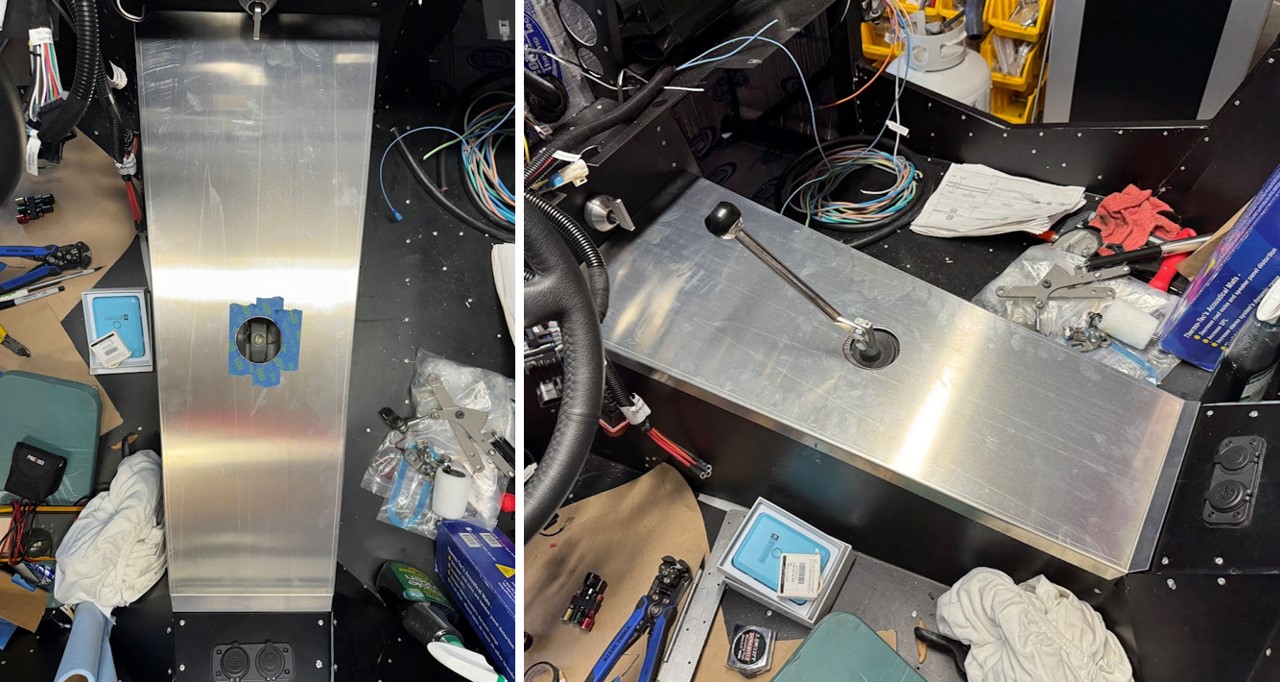
I still need to figure out which cup holders I'm going with - maybe the billet ones from Eddie Motorsports (MS281-43P) and cut the holes for those. After I do that, and the E-brake final mounting, I'll send this trans tunnel top off to a local upholsterer and have them cover it with the same saddle leather as my seats and door cards.
Darryl [dbo_texas]
MKIV #9644 (build thread) (Index)
MK4 Complete Kit | Gen2 crate Coyote | Tremec T56, 3.55 IRS | power steering | hydroboost | dual roll bars | FFR carbon fiber dash | 18" Halibrands + Wilwoods | RT drop trunk kit & turn signal | front battery mount | saddle leather Intatrim Stoneleigh seats + interior accents
-
05-08-2024, 02:18 PM
#176
Senior Member
-
05-08-2024, 05:13 PM
#177
Senior Member
Are you okay with those hex heads on the side? Are you planning to carpet over them? You'll have to clearance the tunnel cover. Button cap screws may be a bit less noticeable under carpet / tunnel cover.
MK4, 427LS3, IRS, T56 Magnum, Wilwoods
-
05-08-2024, 09:00 PM
#178
Senior Member
Originally Posted by
Its Bruce
Are you okay with those hex heads on the side? Are you planning to carpet over them? You'll have to clearance the tunnel cover. Button cap screws may be a bit less noticeable under carpet / tunnel cover.
I will do a quick check but i'm using the FF Metal trans cover which has a little extra clearance on the sides. I think there is room for the thickness of the hex head, but the diameter of the washer I used may show slightly under the lip of the tunnel cover. So I may remove the washer but the hex head won't be visible.
Darryl [dbo_texas]
MKIV #9644 (build thread) (Index)
MK4 Complete Kit | Gen2 crate Coyote | Tremec T56, 3.55 IRS | power steering | hydroboost | dual roll bars | FFR carbon fiber dash | 18" Halibrands + Wilwoods | RT drop trunk kit & turn signal | front battery mount | saddle leather Intatrim Stoneleigh seats + interior accents
-
05-26-2024, 07:50 PM
#179
Senior Member
E-brake mounting finalization
After temporary mounting, I went ahead and disassembled the handle parts and spray painted an epoxy coating on them for corrosion protection. I left the teeth of the gear raw steel as that is going to wear away anyway.
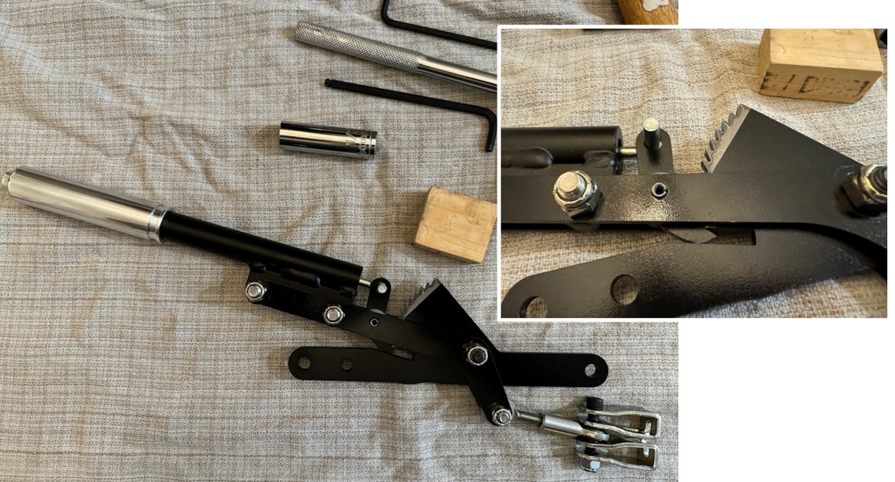
Next up, I re-installed the handle and measured how much to shorten the e-brake cables. I unscrewed the adjuster sleeve so I had about 1/4" of thread engagement and had plenty of threads left to tighten if needed. I marked the cables with blue painters tape, and cut them using a Dremel cutoff wheel. The cable stays together fine (didn't fray).

Next up, I needed to crimp new stop sleeves onto the cables. I used a blade to cut back the vinyl coating off the cables, then crimped the sleeve using this crimper I borrowed from a neighbor. I was planning to use the double sleeve and loop the cable around, but I couldn't get this crimper to work well with the double sleeve, plus it was too large to fit in the FFR saddle. So I went with the single stop sleeve. I put a dab of red Loctite onto the cable, then slid the stop sleeve over it and crimped it down. I tested a crimp on one of the pieces I cut off first, and I did some very rough hard pulls on the stop and the sleeve didn't budge, so I think it will hold (time will tell).
After crimping, this is what it looks like mounted into the saddle. I ended up tightening the turnbuckle to take up a little bit more slack in the cable:

I did a couple of test pulls on the e-brake handle and it seems to work as intended. After locking up I can't turn the rear wheels, but the real test will be when I get it onto the ground and test it on a slope. But for now, I'm calling it good.
Video walkthrough:
Darryl [dbo_texas]
MKIV #9644 (build thread) (Index)
MK4 Complete Kit | Gen2 crate Coyote | Tremec T56, 3.55 IRS | power steering | hydroboost | dual roll bars | FFR carbon fiber dash | 18" Halibrands + Wilwoods | RT drop trunk kit & turn signal | front battery mount | saddle leather Intatrim Stoneleigh seats + interior accents
-
05-26-2024, 08:09 PM
#180
Senior Member
-
05-26-2024, 08:21 PM
#181
Senior Member
-
06-03-2024, 09:02 PM
#182
Senior Member
Bleeding hydraulic clutch and brakes [part 1] - disaster strikes
I finally attempted to bleed the hydraulic clutch & brake circuits this weekend. Let's just say it didn't go according to plan.
I started off by bench bleeding the master cylinder for the hydraulic clutch circuit. This worked just fine --> I ran a 1/4" ID PVC tube from the output of the Wilwood master cylinder back to the clutch reservoir, and slowly pumped the pedal to push fluid through the cylinder until there were no more bubbles in the line. I pinched off the hose each time I released the pedal pressure in order to not draw air back into the system, and then released the kink in the hose with every pedal push, going slowly and making sure the reservoir didn't run dry. This process worked fine and got all the bubbles out of the master cylinder.
Next I disconnected the hose, and connected the braided stainless hydraulic clutch line which I had already attached to the slave cylinder. After attaching a hose to the slave bleeder, I cracked it open and did the pedal-push method to get all the air out of the line. With every release of the pedal, I closed the bleeder to prevent air coming back up through the bleeder hose. Kept doing this until no more bubbles coming out of the bleeder valve. Closed the bleeder valve for good after several pedal pushes with no bubbles. All good so far.
Here's where things started to go wrong. After closing the bleeder, I pushed on the pedal expecting it to be somewhat firm, and slowly it kept moving down and felt soft. After closer inspection, I found that there is fluid slowly leaking around the fitting going into the slave cylinder. It only leaks under pedal pressure. There's a video below, but after talking to the shop that this came from, I have a good suspicion about what he issue is (more on this later).

Video of the leak
After this, I decided to try my luck at the hydroboost brakes. I started by setting it up to bench bleed the master cylinder. Same setup as the clutch - I ran 2 tubes from the outputs of the master cylinder back into the front & rear brake reservoirs. Here's what this setup looks like (using 1/4" ID PVC hose):
However, as soon as I filled either reservoir, brake fluid started gushing from the banjo connections on the master cylinder. This is without any pedal pressure - just leaking like crazy from the banjo connector. It looked like fluid was gushing from both sides of the fitting where the crush washers were. I've never used banjo fittings and didn't assemble these, so I had no idea what to expect or how these fitting are supposed to work. The immediate reaction from the Facebook group was that the banjo crush washers weren't sealing properly and it sure looks like that is the case.
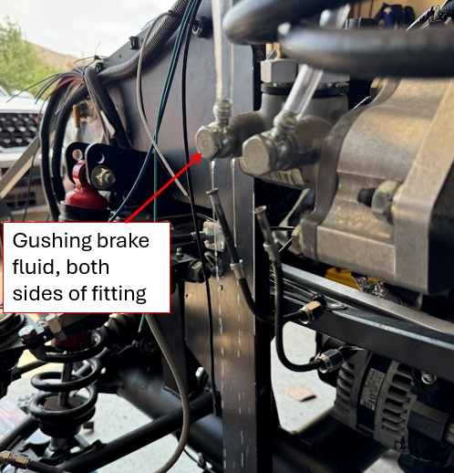
Brake hydroboost master cylinder banjo fitting leak:
TROUBLESHOOTING: After reaching out to the component supplier, I think I have a pretty good idea what's going on with both the hydraulic clutch fitting AND the banjo fittings on the brake master cylinder. Sounds like for the setup I have, the vendor typically shortens the fittings by about 1mm because at the default length they bottom out and prevent full seating/sealing. By shortening the fitting (or banjo bolt) slightly, it allows them to thread in a little deeper and full seal. Sounds like maybe these fittings didn't get modified prior to assembly. I don't have the full history on these parts since I got my kit from another builder, but I believe that is what's going on after studying both leaks.
So this will be my next step - drain the clutch circuit, remove the fitting in the slave cylinder, shorting by about 1mm and then re-install and re-bleed the system. For the banjos, the brake circuit is already drained (all over the garage floor - lesson learned - put a catch pan under that). So I just need to remove the banjo bolts and shorten them slightly, then retighten everything down and try to bench bleed the master again. IF that is successful, I can try bleeding all 4 brakes after that.
Darryl [dbo_texas]
MKIV #9644 (build thread) (Index)
MK4 Complete Kit | Gen2 crate Coyote | Tremec T56, 3.55 IRS | power steering | hydroboost | dual roll bars | FFR carbon fiber dash | 18" Halibrands + Wilwoods | RT drop trunk kit & turn signal | front battery mount | saddle leather Intatrim Stoneleigh seats + interior accents
-
Post Thanks / Like - 0 Thanks, 1 Likes
-
06-10-2024, 11:55 AM
#183
Senior Member
Cup Holder Install
While waiting for some new fittings to resolve the brake & clutch leaks, I decided to knock out the final change on the transmission tunnel which was to mount the cup holders.
I had previously traced the tunnel cross brace locations on the bottom side of the trans tunnel. I debated where to actually place the cup holders. I wanted them to be symmetric in the tunnel, but the only place to do that is under the dash. Any other locations in the tunnel would have had to be staggered to avoid the cross-braces or T56 transmission body underneath. So I settled on placing them under the dash, which means I won't be able to put a very large cup in them. It easily holds 12oz cans and some smaller thermos style cups, just not really tall ones.
The cup holders I used are from Summit, Eddie Motorsports Billet Aluminum Drink Holders MS281-43P. I had previously bought a cheap pair from Amazon, but I saw these in Lidodrip's build and they look way better.

And here's the final location:

Now that the transmission tunnel has all the holes cut in it, I'm ready to send this off to an upholstery shop to install the leather matching my seats. I do plan to add diamond stitch also.
Darryl [dbo_texas]
MKIV #9644 (build thread) (Index)
MK4 Complete Kit | Gen2 crate Coyote | Tremec T56, 3.55 IRS | power steering | hydroboost | dual roll bars | FFR carbon fiber dash | 18" Halibrands + Wilwoods | RT drop trunk kit & turn signal | front battery mount | saddle leather Intatrim Stoneleigh seats + interior accents
-
06-10-2024, 11:59 AM
#184
Senior Member
Footbox Blowers - Part 1
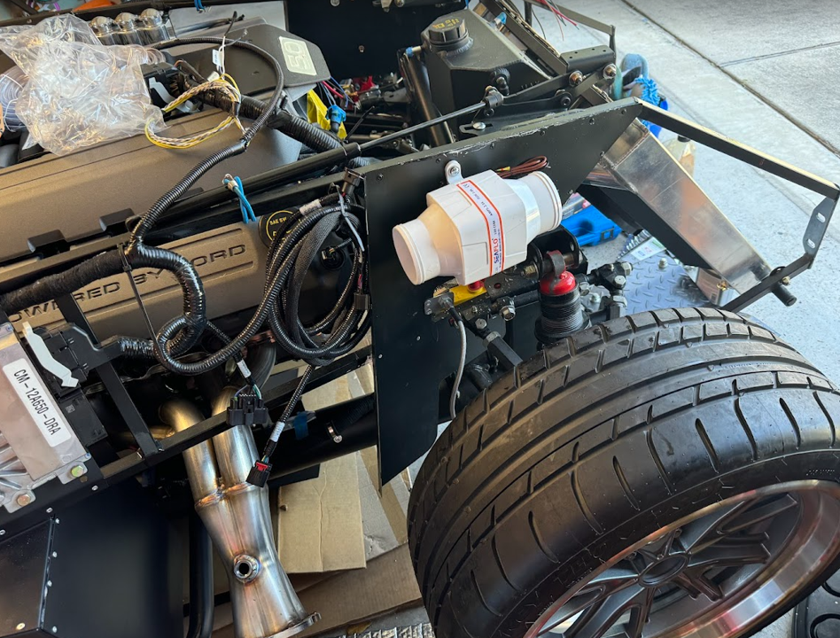
While killing time waiting for some other parts to fix the leak in the brake & clutch circuits, I decided to mount both footbox blowers. I'll do a full writeup on this once I get the blast gates, hoses & electrical complete, but for now I have the two blowers mounted. I used M6 rivet nuts on the F-panels for mounting. I may need to shift the DS location slightly - I'm worried the hose coming off the blower will not clear the hydroboost master cylinder, so I may need to shift it forward a few inches to give me more room to make the job around the hydroboost.
Driver Side:

Passenger Side:
Darryl [dbo_texas]
MKIV #9644 (build thread) (Index)
MK4 Complete Kit | Gen2 crate Coyote | Tremec T56, 3.55 IRS | power steering | hydroboost | dual roll bars | FFR carbon fiber dash | 18" Halibrands + Wilwoods | RT drop trunk kit & turn signal | front battery mount | saddle leather Intatrim Stoneleigh seats + interior accents
-
06-20-2024, 09:37 PM
#185
Senior Member
Hydraulic clutch and brake bleed [part 2] - HELP!
The fix for the hydraulic clutch fitting ended up being pretty simple. After draining that circuit and removing the port on the slave cylinder, I inspected the aluminum crush washer an noticed the indentation from the port seating was off-center.
I got a new copper crush washer, re-installed it with no other modifications, and was able to successfully bleed the clutch circuit. I did re-bleed the Wilwood master cylinder prior to bleeding the clutch line. But it holds pressure and doesn't leak. The pedal does feel pretty damn stiff though....I'll have to play with it more after I clear out some junk from the driver's seat and see if it is too much pressure or if it just feels that way doing it with my hand. I confirmed with the supplier that I have the correct master cylinder size for my setup (13/16").
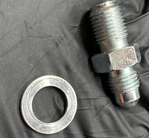
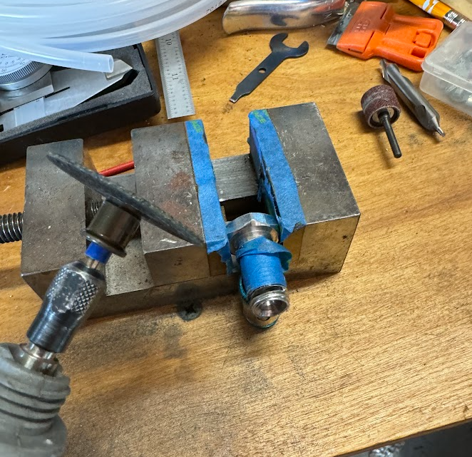
I also received the new banjo bolts from supplier for the hydroboost master cylinder. They added a big chamfer to the inlet port (to theoretically clear the port inside the master cylinder).
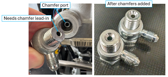
Unfortunately this didn't do the trick. They didn't modify the length of the bolt at all, and the bolt was still bottoming out in the master cylinder before the bolt could squeeze the banjo fitting and crush washers. I took out the Dremel and cut off about 3mm from both banjo bolts and re-drilled the chamfer on the port opening using a center drill. This did the trick and I was able to successfully clamp the fitting and crush washers. I also added some Permatex liquid thread sealant just to be safe.
Then I re-did the bench bleed on the hydroboost master cylinder (both front & rear together).
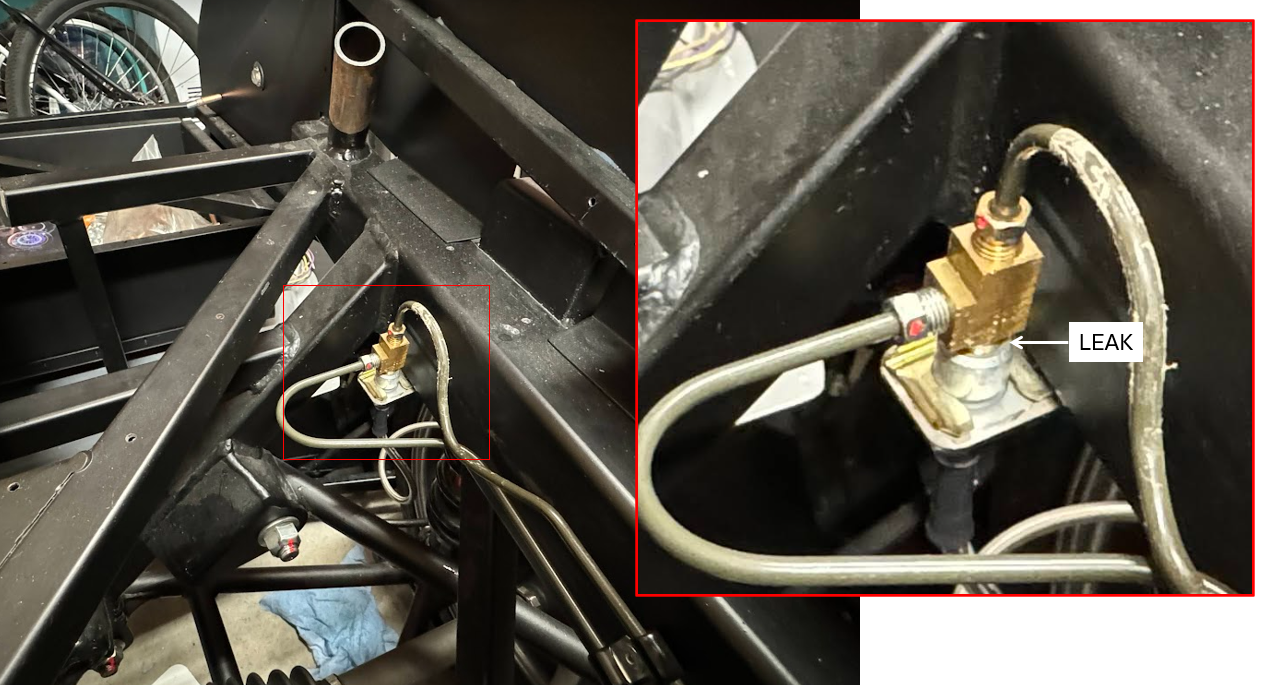
Then I started bleeding the rear passenger side brake caliper (farthest from the master). I used my vacuum bleeder kit because it worked pretty well on the clutch slave. I have the Wilwood IRS brake setup, so I started with the outboard bleeder valve (per Wilwood instructions). On the rear brakes, there are 2 bleeder valves you need to bleed. However, I wasn't ever able to get it to stop producing bubbles. After inspecting the connections on the rear circuit, I fount a small puddle under the 3-way connection in the trunk area where the brake lines split to the left and right sides of the car. I tried tightening all the fittings, but it just keeps leaking from where the aluminum fitting goes into the brass Tee fitting. I think my only recourse is to drain the circuit, remove the fittings, and use some liquid thread seal on that fitting to see if that does the trick. ANY OTHER ADVICE ON THIS BEFORE I PROCEED?
Darryl [dbo_texas]
MKIV #9644 (build thread) (Index)
MK4 Complete Kit | Gen2 crate Coyote | Tremec T56, 3.55 IRS | power steering | hydroboost | dual roll bars | FFR carbon fiber dash | 18" Halibrands + Wilwoods | RT drop trunk kit & turn signal | front battery mount | saddle leather Intatrim Stoneleigh seats + interior accents
-
07-07-2024, 06:59 PM
#186
Senior Member
Brake bleeding - Part 3 (SUCCESS!...I think)
I left off with a leak on the rear "tee" connection. To fix this, I just drained the rear circuit and completely removed the brass "tee", cleaned everything up, and re-assembled. Per the advice of someone on the Facebook group (Factory Five Builder), they suggested for every brake connection to tighten it, then loosen it, then tighten it and do this one more time (for total of 3 tighten cycles). I followed the advice, and low and behold no more leak. Go figure.
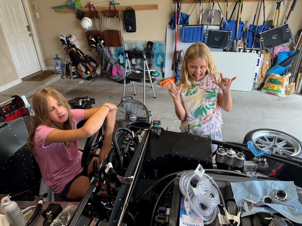
Next up, I had my 2 favorite helpers (12yr & 9 yr) give me a hand with the brakes. The 12yr old was working the pedal and the 9yr old was keeping an eye on the reservoir fluid levels and notified me when I needed to top them off.
We filled the reservoirs, re-bled the master cylinder (on the hydroboost), and then let the system gravity bleed for a bit. Next I had the 12yr old pump the brake and hold, then I cracked the bleeder, then closed it and she let off the pedal. We followed the Wilwood instructions and did the PS rear upper outboard bleeder first, then the upper inboard bleeder. Then did the DS rear, then PS front (single upper bleeder), then finally DS front (single upper bleeder). After all this, there were no leaks found, and all the bleeders were pumping fluid with no bubbles. However, the pedal still wasn't firm and was still going all the way to the floor. The pads also weren't gripping the rotors. It felt like there was air still trapped in the circuits somewhere. I posted to another thread on the forum HERE, and got some great suggestions.
In the end, I didn't want to spend another day building a DIY pressure bleeder, and Henry Renaud (65 Cobra Dude on the forum) suggested to try this method instead:
-with bleeder closed, 6 pumps of the pedal and hold on the 6th push
-with pedal pressure applied, crack bleeder and let air bubbles out
-close bleeder
-repeat several times, filling reservoir as needed
Today we tried this method, and sure enough it seems to have worked. We got a lot more air out of the system on each corner, and slowly got a firm pedal. After we were finished, we held pedal pressure for about 3 minutes and it stayed firm. I checked for leaks and so far so good. Finally, with the car up on jacks we spun the wheels and confirmed they lock up when the pedal is applied. I'll check everything again in a few days just to confirm no leaks and everything is working as intended, but for now I think the brakes are FINALLY done.
Darryl [dbo_texas]
MKIV #9644 (build thread) (Index)
MK4 Complete Kit | Gen2 crate Coyote | Tremec T56, 3.55 IRS | power steering | hydroboost | dual roll bars | FFR carbon fiber dash | 18" Halibrands + Wilwoods | RT drop trunk kit & turn signal | front battery mount | saddle leather Intatrim Stoneleigh seats + interior accents
-
07-12-2024, 03:46 PM
#187
Senior Member
Fluids planning - Coyote Gen2 + T56 + 2018 IRS + power steering/hydroboost
I'm almost to the point where I'm ready to fill all the fluids. I still need to hook up some plumbing lines before I can fill, but wanted to run my plans by the group for input. Let me know if you see any issues with my plans below. I have a couple of questions sprinkled in as well.
Engine Oil (Gen2 Coyote w/Moroso Pan):
- I think I need about 8-10 quarts (FFR instructions say 8 quarts, some on the forum reported this combo took 10)
- Planning ot use Mobil 1 Advanced Full Synthetic Motor Oil 5W-20
Coolant:
- I think I need 3-4 gallons of any Dex-Cool antifreeze - I'm just planning daily driving so I imaging any store bought stuff should work fine
Power steering (KRC Coyote Setup):
- power steering alone needs 1.5 quarts (1.4L) I think, but with the hydroboost I'm guessing I need more? Anyone with this combo have a recommendation on total volume needed?
- I'm planning to use the Genuine Honda Power Steering Fluid 08206-9002 which seems to pretty much be what everyone uses.
Transmission (Tremec T56 TUET11010):
- Instructions say it takes about 7.5 pints (~4.1 quarts)
- I am a little confused on what to use here. These are some options I've seen based on other build threads, and there are different price points here ($6.99/quart - $20/quart). Here are some different options I'm considering - would love some input on which of these might be good to use (preferably something easy to get from auto store):
- GM Synchromesh - Is this the same as the ACDelco 769476 GM OEM 10-4006 Synchromesh Transmission Fluid?
- Pennzoil Synchromesh
- Mobil 1 Automatic Transmission Fluid (ATF) - recommended in the Tremec tech bulletin
- Tremec HP MTF oil - this is the one the T56 service manual recommends, but its hard to get so I don't plan on using it
- Any Dexron-III fluid - also recommended in T56 service manual. I read on someone's thread that anything above Dexron-III will also work. Is that accurate?
- Valvoline Dexron VI/Mercon LV ATF 822405
Differential (2018 IRS)
- I read in the instructions this needs about 1.65 quarts. I've also seen a lot of discussion on the forum that some were pre-filled with oil, some partially filled, and some didn't have any oil at all. Mine is form 2019 and I haven't checked if it has oil yet. I plan to crack the drain plug and check. If it does have oil, I'll see if I can smell the friction modifier was added. If it has both, I plan to just top it off. If not, I'll use the recommended Motorcraft combo from the FFR instructions most likely
- 4oz Motorcraft® Additive Friction Modifier (U.S.) XL-3 (U.S.) (EST-M2C118-A)
- 3.15-3.3 pints (~1.5L or <2 quarts) Motorcraft® SAE 75W-85 Synthetic Hypoid Gear Lubricant XY-75W85-QL (WSS-M2C942-A)
- I saw some discussion on the forum that heavier oils can be used here instead of the Motorcraft combo. Something like Valvoline SynPower SAE 75W-140 Full Synthetic Gear Oil which already has the friction modifier added. Can anyone confirm if this is a suitable alternative to the Motorcraft combo which I think you have to get at a Ford dealer?
Brakes & hydraulic clutch
- I already filled these using Liqui Moly DOT 4 Brake Fluid. 1L bottle was plenty to fill both.
Last edited by dbo_texas; 07-12-2024 at 03:57 PM.
Darryl [dbo_texas]
MKIV #9644 (build thread) (Index)
MK4 Complete Kit | Gen2 crate Coyote | Tremec T56, 3.55 IRS | power steering | hydroboost | dual roll bars | FFR carbon fiber dash | 18" Halibrands + Wilwoods | RT drop trunk kit & turn signal | front battery mount | saddle leather Intatrim Stoneleigh seats + interior accents
-
Post Thanks / Like - 1 Thanks, 0 Likes
-
07-12-2024, 08:15 PM
#188
Senior Member

Originally Posted by
dbo_texas
Power steering (KRC Coyote Setup):[*]power steering alone needs 1.5 quarts (1.4L) I think, but with the hydroboost I'm guessing I need more? Anyone with this combo have a recommendation on total volume needed?[*]I'm planning to use the Genuine Honda Power Steering Fluid 08206-9002 which seems to pretty much be what everyone uses.
I had conversations with KRC with mine during the Coupe build. Explained I typically used the Honda power steering fluid. They recommended against it. I don't recall the specific reason. Of course they recommended their fluid. Since it doesn't take much, I followed their guidance and ordered some from Summit. Would be worth a phone call IMO.
Originally Posted by
dbo_texas
Transmission (Tremec T56 TUET11010):
- Instructions say it takes about 7.5 pints (~4.1 quarts)
- I am a little confused on what to use here. These are some options I've seen based on other build threads, and there are different price points here ($6.99/quart - $20/quart). Here are some different options I'm considering - would love some input on which of these might be good to use (preferably something easy to get from auto store):
- GM Synchromesh - Is this the same as the ACDelco 769476 GM OEM 10-4006 Synchromesh Transmission Fluid?
- Pennzoil Synchromesh
- Mobil 1 Automatic Transmission Fluid (ATF) - recommended in the Tremec tech bulletin
- Tremec HP MTF oil - this is the one the T56 service manual recommends, but its hard to get so I don't plan on using it
- Any Dexron-III fluid - also recommended in T56 service manual. I read on someone's thread that anything above Dexron-III will also work. Is that accurate?
- Valvoline Dexron VI/Mercon LV ATF 822405
When I did mine several years ago, the Tremec instructions for T-56 were Dexron III / Mercon Spec ATF. I used Valvoline Dexron-III / Mercon. Standard parts store item.
Build 1: Mk3 Roadster #5125. Sold 11/08/2014.
Build 2: Mk4 Roadster #7750. Sold 04/10/2017.
Build Thread
Build 3: Mk4 Roadster 20th Anniversary #8674. Sold 09/07/2020.
Build Thread and
Video.
Build 4: Gen 3 Type 65 Coupe #59. Gen 3 Coyote. Legal 03/04/2020.
Build Thread and
Video
Build 5: 35 Hot Rod Truck #138. LS3 and 4L65E auto. Rcvd 01/05/2021. Legal 04/20/2023.
Build Thread. Sold 11/9/2023.
-
Post Thanks / Like - 1 Thanks, 0 Likes
-
07-13-2024, 08:04 PM
#189
Senior Member
Originally Posted by
edwardb
I had conversations with KRC with mine during the Coupe build. Explained I typically used the Honda power steering fluid. They recommended against it. I don't recall the specific reason. Of course they recommended their fluid. Since it doesn't take much, I followed their guidance and ordered some from Summit. Would be worth a phone call IMO.
When I did mine several years ago, the Tremec instructions for T-56 were Dexron III / Mercon Spec ATF. I used Valvoline Dexron-III / Mercon. Standard parts store item.
Thanks for the feedback Paul. I may go with the Valvoline Dexron-III / Mercon for the transmission since it's easy to get. I'll dig a little on the KRC power steering fluid question but may just get the KRC fluid from Summit as suggested.
Darryl [dbo_texas]
MKIV #9644 (build thread) (Index)
MK4 Complete Kit | Gen2 crate Coyote | Tremec T56, 3.55 IRS | power steering | hydroboost | dual roll bars | FFR carbon fiber dash | 18" Halibrands + Wilwoods | RT drop trunk kit & turn signal | front battery mount | saddle leather Intatrim Stoneleigh seats + interior accents
-
07-23-2024, 09:21 AM
#190
Senior Member
Brake pads dragging rotors after bleeding
I noticed after bleeding the brakes that the brake pads on all 4 rotors drag just slightly. On the front DS it's enough to put marks on the black paint on the rotor. I've been told this black paint will rub off after bedding the brakes - I assume Wilwood paints the rotors as a form of corrosion protection? As this is my first build, I wasn't sure if this is typical or is something is off. I've got the Wilwood brakes installed. It looks similar front and rear, although on the rear its a little more difficult to tell how much drag because of the differential. In the rear, it also looks like the emergency brake pads also slightly rub the rotor even with no tension on the cable. But the pivot arm is against the hard-stop nub in the caliper housing, so I don't think this is an issue.
I posted to the Facebook group (Factory Five Builder) and got many comments from some experienced builders that this is typical/common to have the pads in contact with the rotor, and that after bedding the pads the slight dragging may go away. My plan for now is to let it be and just keep an eye on it after bedding the brakes. I did re-bleed the system yesterday one more time just to make sure there was no air (and there wasn't).
Here's a video showing the dragging:
Not sure if anyone can make out any issues from these pictures, but the rotor does appear to be centered between the pads. Before I bled the brakes, the pads were not touching and the rotor was perfectly centered, and in the front at least they would spin freely. Only after bleeding did the slight dragging start.


Hydroboost Question:
While messing with the brakes I also noticed the two ports on the top of my hydroboost master cylinder look almost like they are pushed upwards slightly. I'm not familiar with the hydroboost system - can anyone tell me is this normal? Do these just simply push down into the MC, or do they thread down into it?

Darryl [dbo_texas]
MKIV #9644 (build thread) (Index)
MK4 Complete Kit | Gen2 crate Coyote | Tremec T56, 3.55 IRS | power steering | hydroboost | dual roll bars | FFR carbon fiber dash | 18" Halibrands + Wilwoods | RT drop trunk kit & turn signal | front battery mount | saddle leather Intatrim Stoneleigh seats + interior accents
-
07-23-2024, 10:43 AM
#191
Senior Member
The black finish on the Wilwood rotors (whatever it is) will wear off as you use and bed the brakes. As long as you have them centered (looks like you do) there’s nothing else to do. 100% normal for disc brakes to drag slightly when at rest. Jack your DD up and spin one of the tires. You will hear a slight scraping sound of the pad against the rotor. Same thing here.
Build 1: Mk3 Roadster #5125. Sold 11/08/2014.
Build 2: Mk4 Roadster #7750. Sold 04/10/2017.
Build Thread
Build 3: Mk4 Roadster 20th Anniversary #8674. Sold 09/07/2020.
Build Thread and
Video.
Build 4: Gen 3 Type 65 Coupe #59. Gen 3 Coyote. Legal 03/04/2020.
Build Thread and
Video
Build 5: 35 Hot Rod Truck #138. LS3 and 4L65E auto. Rcvd 01/05/2021. Legal 04/20/2023.
Build Thread. Sold 11/9/2023.
-
Post Thanks / Like - 0 Thanks, 1 Likes
-
08-19-2024, 08:33 PM
#192
Senior Member
-
08-19-2024, 08:49 PM
#193
Senior Member
-
08-24-2024, 10:04 PM
#194
Senior Member
Differential, Transmission, and Engine Oil Filling
I went out and bought all the oils and fluids for the car, so this weekend I spent some time filling the rear differential, transmission, and engine with the appropriate oils. Here is what I used:
- Differential (2015 IRS): Motorcraft® SAE 75W-85 Synthetic Hypoid Gear Lubricant XY-75W85-QL (WSS-M2C942-A) --> My transmission already has some oil in it, so all I did was top it off. Based on the smell, I'm pretty sure it already had the recommended 4oz of friction modifier (Motorcraft XL-3) so I didn't add any more of that. I only needed to a little over 1/2 quart before it started spilling out the fill hole.
- Transmission: Valvoline DEX/MERC ATF (DEXRON-III / MERCRON - Tremec recommends any DEXRON-III automatic transmission fluid. Mine was dry, and it took about 3.75 quarts before it started spilling out the fill hole.
- Engine (Coyote Gen II): Mobil 1 Advanced Full Synthetic Motor Oil 5W-20 --> I bought 2 of the big 5 quart jugs and used a total of 9.5 quarts
DIFFERENTIAL GEAR OIL
Starting with the rear differential, last week I found that the fill plug was completely mangled by whomever installed it previously. I had a hard time getting it out with the 1/2" square ratchet driver, but eventually it broke free. I ended up buying a new plug on Amazon, but not the OEM 1/2" square hole style. I couldn't find that part anywhere except ordering direct from a Ford dealership (P/N 390943S101). Would have been about $25 for the part and shipping. Turns out this diff uses a 1/2-14 NPT plug size with built in magnet to grab any floating metal shavings. I ended up buying a replacement on Amazon which had an external 1/2" drive, but it works just as well and only cost me about $8 with free shipping. This part works just fine and you can see new new plug at the top:
To fill the differential, I used a Slippery Pete fluid pump purchased from Amazon for $11. I could have rigged something DIY up, but for $11 I got 2 pumps which I used the other one for the transmission. So I hit the easy button. It screws right onto the quart bottles, and comes with the hoses. You just pump/fill until the transmission fluid starts spilling out of the fill port. As mentioned before, my differential already had some oil, so I only added about 1/2 quart.

TRANSMISSION FLUID
On this one, the plugs were fine so I just unscrewed the upper fill plug, and used the other Slippery Pete hand pump to fill the transmission. It took about 3.75 quarts before spilling out the port.

ENGINE OIL
My engine is a new crate engine but it was purchased by the original build from Forte's back in 2019. So it's been sitting for quite a while. I decided to play it safe and prime the engine with oil vs. just pouring it into the normal oil fill. This has been discussed/debated a bit on the forum as to whether it is necessary, but personally I think its worth the $13 investment. Shout out to JohnK's Build Thread (Post #212) for documenting (and also answering my questions via PM). You basically use a cheap $11 garden sprayer with a 1/8 NPT - 3/16 barb adapter on the end. Screw that into the oil sender unit port on the DS of the engine, and manually pump 5 quarts of oil into the engine. This forces oil up into the oil filter as well as all the oil galleys in the engine. After priming with 5 quarts, let pressure out of garden sprayer and remove the hose and replace the oil pressure sender unit. Only about an ounce of oil spilled out the pressure sender port when I unscrewed the hose, so it wasn't too messy. Then, I filled the additional 4.5 quarts via traditional method, bringing the total to 9.5 quarts. I used the dipstick to verify it was at the FULL line. Here's a couple of photos:
Had some trouble getting the oil sender plug removed --> used a crow-foot adapter + ratchet and was able to get it off:
Here's the garden sprayer setup used:

NEXT UP:
- Back to the heater hoses --> will add the other 2 hoses to the engine heads, clamp & add mesh loom around them to clean them up a bit
- Connecting the coolant hoses and Coyote intake items
- Finish the heater bypass valve choke wire bracket
- Back to electrical to test all circuits
Darryl [dbo_texas]
MKIV #9644 (build thread) (Index)
MK4 Complete Kit | Gen2 crate Coyote | Tremec T56, 3.55 IRS | power steering | hydroboost | dual roll bars | FFR carbon fiber dash | 18" Halibrands + Wilwoods | RT drop trunk kit & turn signal | front battery mount | saddle leather Intatrim Stoneleigh seats + interior accents
-
Post Thanks / Like - 0 Thanks, 1 Likes


 Thanks:
  Likes:


 Reply With Quote

