-
Senior Member


Originally Posted by
Fman

Nice work! What did you end up setting your Koni shocks at? Hard or Soft ride setting?
I found some old threads on the subject. I found one where doctor Kleiner said that the soft setting was ideal and what FFR had in mind. Honestly my last car had elite handling. Now having IRS I’m excited that it will be getting better. It’s a rough ride though. I can’t imagine off the track wanting it any stiffer.
Last edited by Blitzboy54; 09-03-2024 at 03:14 PM.
-
Post Thanks / Like - 0 Thanks, 1 Likes
 Fman
Fman liked this post
-
Don't forget to insert your vent plug into your pumpkin and run a vent line. Check your lube level also.
-

Originally Posted by
Blitzboy54

Well, it happened. The Roadster fairy arrived early this morning. Just before it got here I heard a rumble, I wasn't sure what it was then realized it was our friend Scott and his Daytona Coupe. He dragged himself out of bed at 6:00 in the morning to come help me take delivery. A real team player.
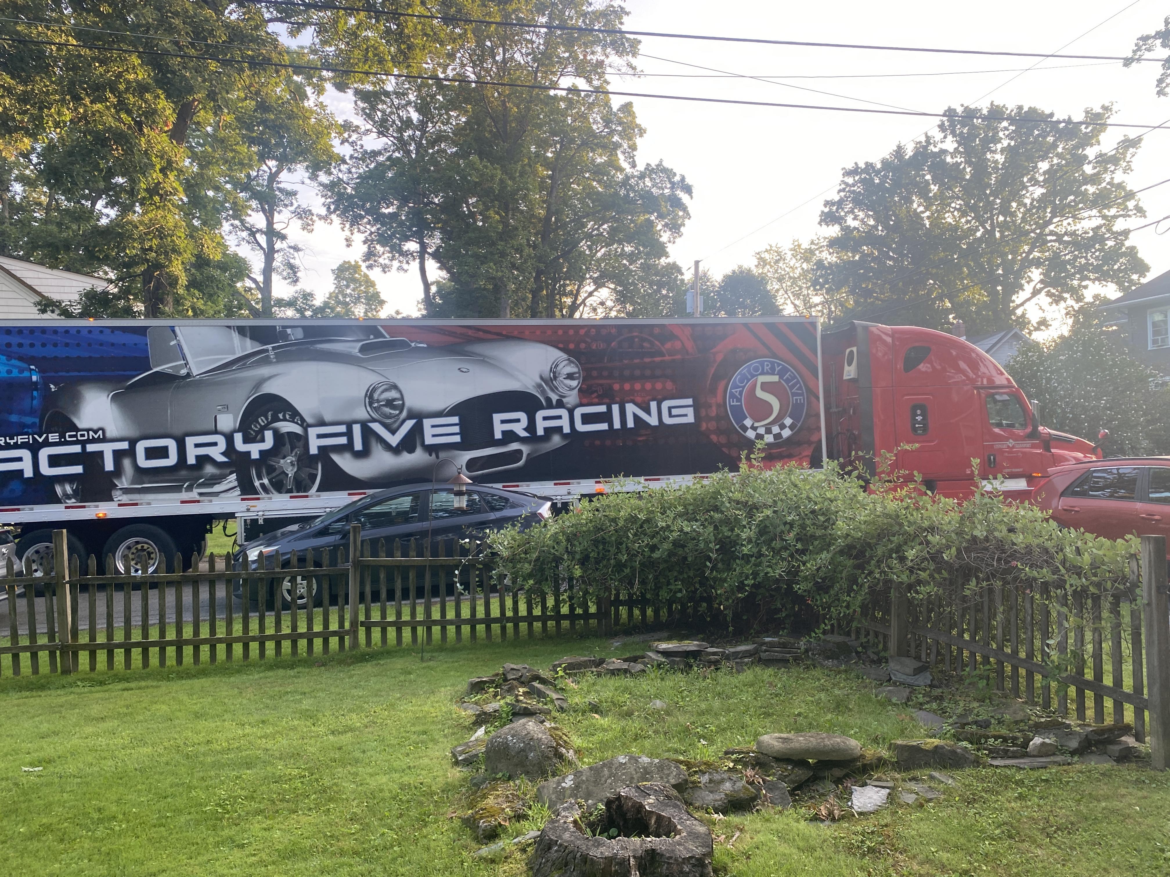
The truck arrived packed to the gills. A little fun fact, the driver was the same fella that dropped off my first build. He remembered the house and noticed it had been painted since the last time he was here. I was honestly impressed.
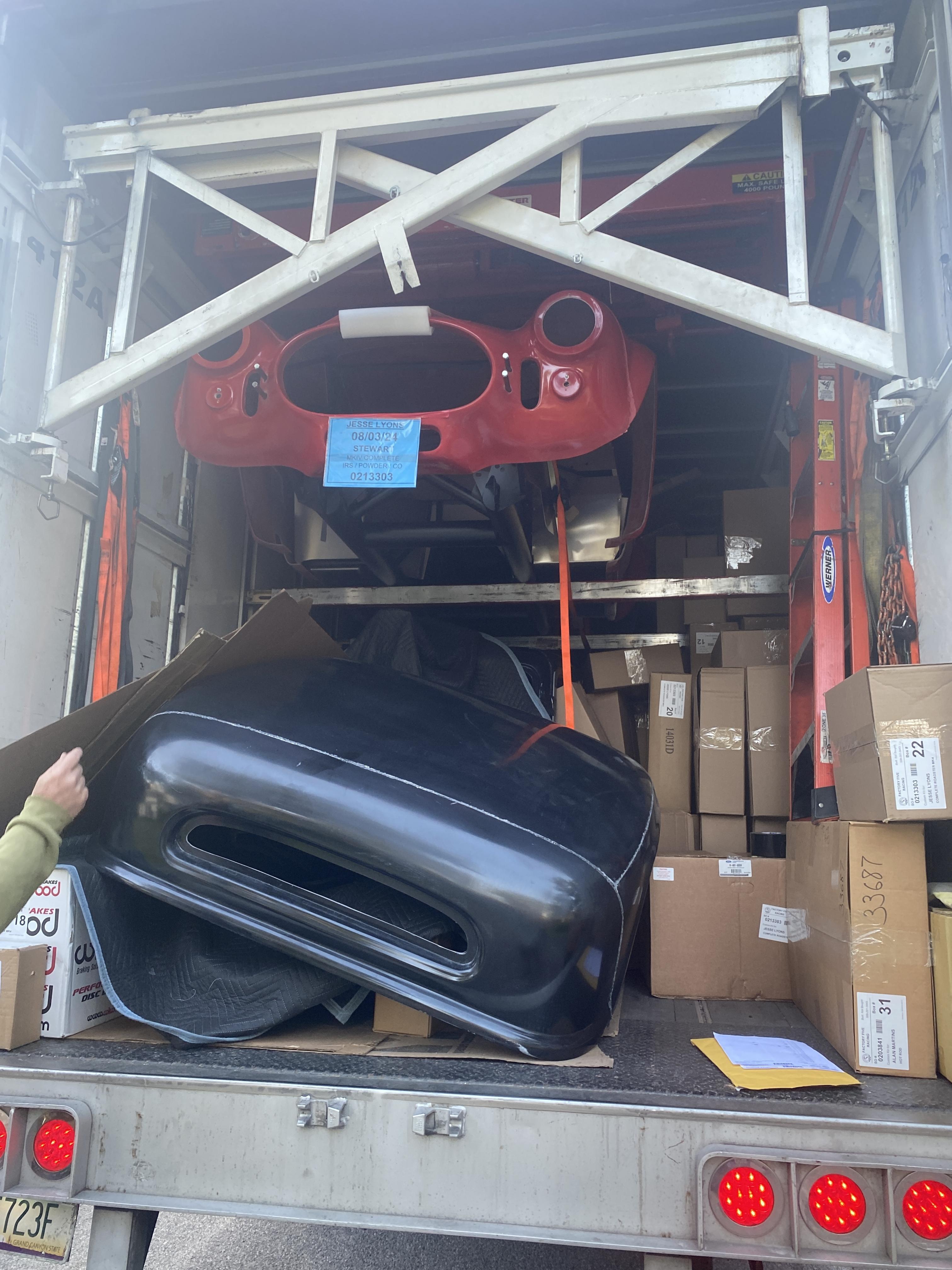
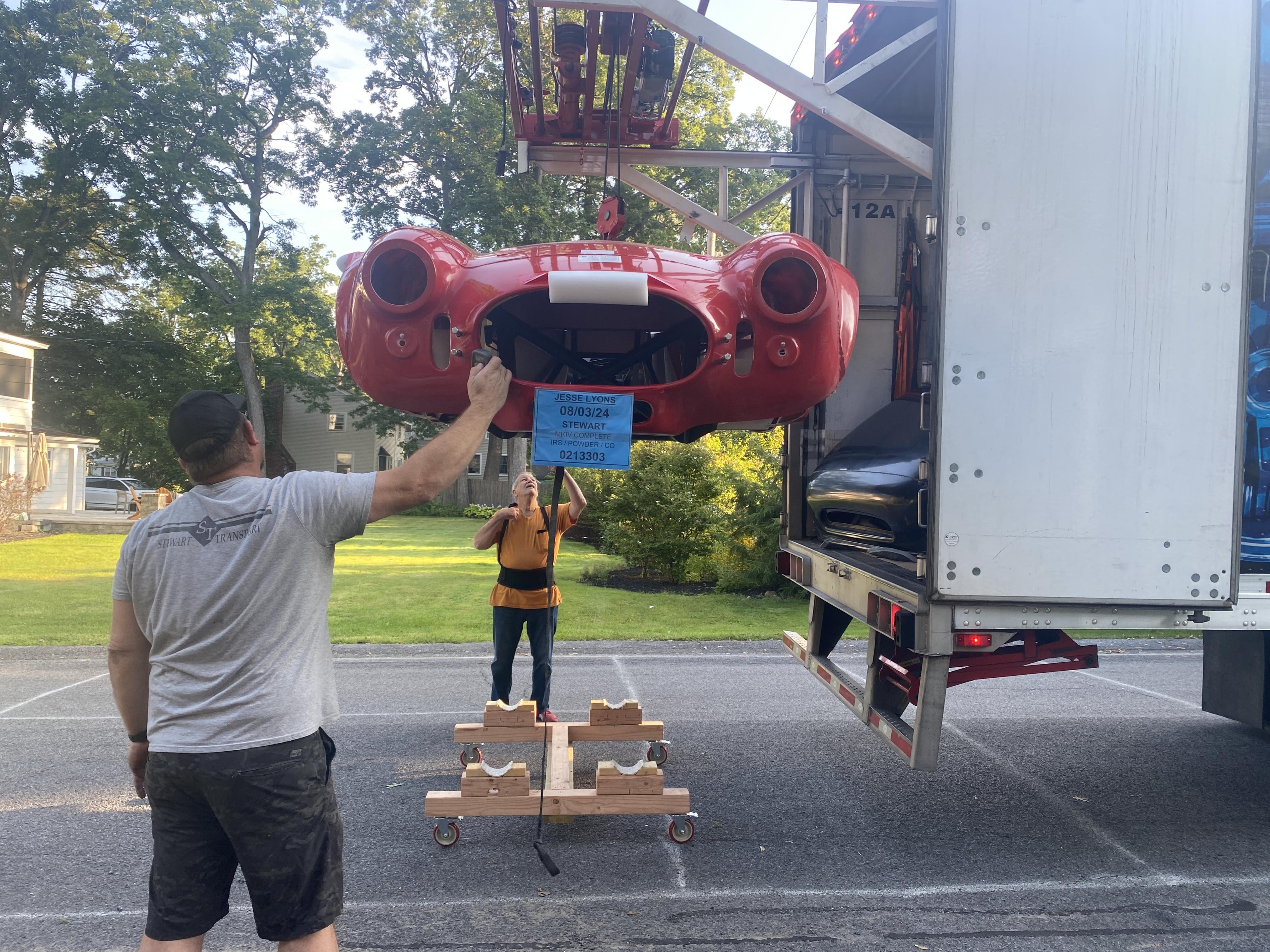
Scott jumping in with both feet and his load bearing belt.
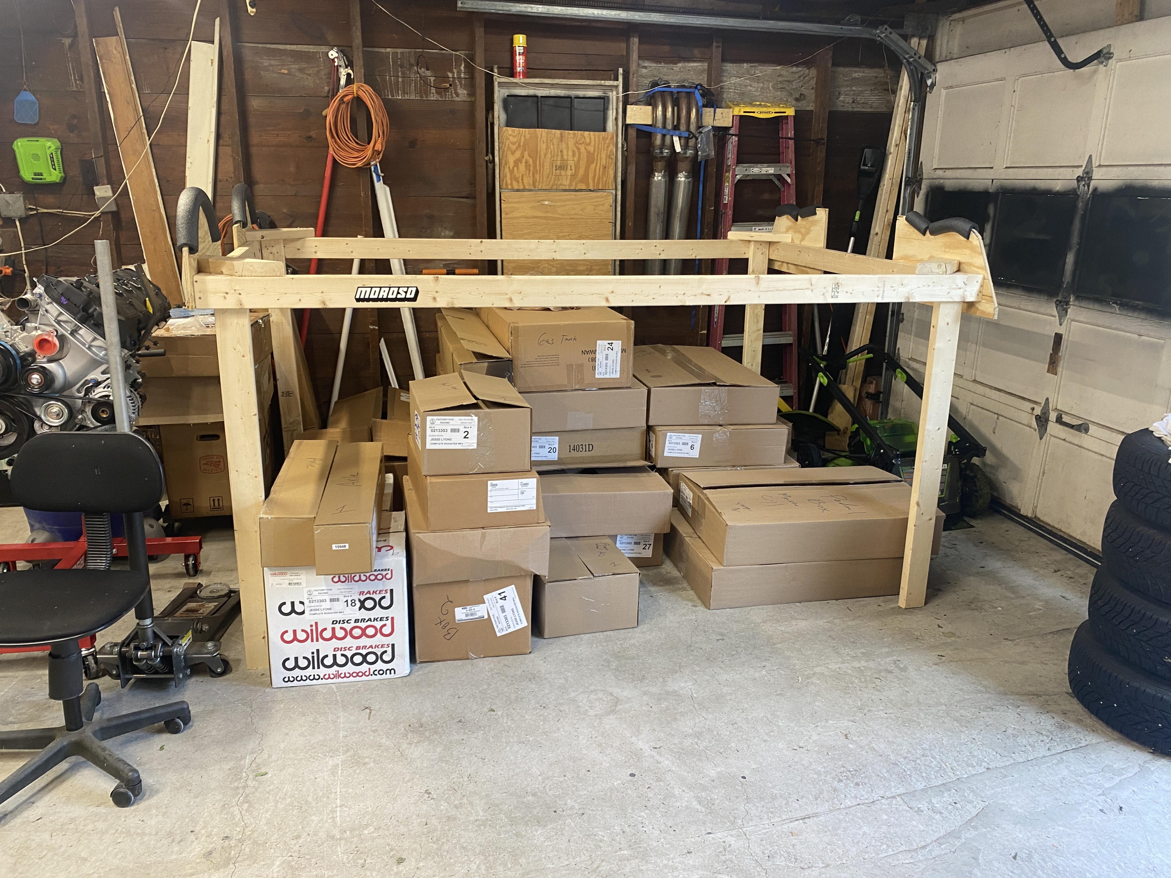
We dug through all the boxes and pulled through the inventory. The only thing missing is I ordered a 2 sets of 2 inch roll bars and grommets. They were supposed to ship with my delivery but missed the truck. I assume they will be shipped along later. The only back ordered item was my drive shaft. Pretty impressive compared to my last build where I had 3 pages.
Once inventory was complete I tucked away the boxes based on need. The parts most likely to be used first up front. Nice thing about having done this before is knowing what you need and when.
Hi Jesse, looking forward to reading through your build thread as I'm building mine at the same time.
One thing you mentioned above was that you had ordered 2 sets of 2" roll bars. I didn't think 2" was an option any more. Or did you mean 1 1/2" roll bars?
Thanks,
Jesse
-
Senior Member


Originally Posted by
RogerRoger88

Hi Jesse, looking forward to reading through your build thread as I'm building mine at the same time.
One thing you mentioned above was that you had ordered 2 sets of 2" roll bars. I didn't think 2" was an option any more. Or did you mean 1 1/2" roll bars?
Thanks,
Jesse
Thank you and welcome aboard!
The kit comes standard with 1.5" role bars. This is what I had on my last build. Mk I-III used 2". Because of that FFR still supports the 2 inch bars. You can purchase them directly from the parts catalog (google factory five parts). I purchased 2 sets with grommets. They do not fit on the studs that are in the frame BUT it turns out you can makes sleeves using 1.25" I.D./1.75" O.D. .250" wall tubing. This will allow them to fit but you will need to drill through quite a bit more steel. Some guys shorten them, I will not. First I don't want to rework the back stud and second is the height is set to keep your head under it if there is a roll over. While a think shorter bars would look even better I am not confident making that change. For those reasons I will keep the geometry the same. But for my money the 2 inch roll bars are head and shoulders better looking than the 1.5".
Last edited by Blitzboy54; 09-03-2024 at 02:10 PM.
-

Originally Posted by
Blitzboy54

Thank you and welcome aboard!
The kit comes standard with 1.5" role bars. This is what I had on my last build. Mk I-III used 2". Because of that FFR still supports the 2 inch bars. You can purchase them directly from the parts catalog (google factory five parts). I purchased 2 sets with grommets. They do not fit on the studs that are in the frame BUT it turns out you can makes sleeves using 1.25" I.D./1.75" O.D. .250" wall tubing. This will allow them to fit but you will need to drill through quite a bit more steel. Some guys shorten them, I will not. First I don't want to rework the back stud and second is the height is set to keep your head under it if there is a roll over. While a think shorter bars would look even better I am not confident making that change. For those reasons I will keep the geometry the same. But for my money the 2 inch roll bars are head and shoulders better looking than the 1.5".
Thanks for the info! Not sure if I'm gonna spend an extra $800 on new dual black roll bars and grommets. Drilling through steel I can handle. Reworking geometry not so much.
-
Senior Member

I went with the Breeze bar, 1.75" diameter. It's a welded construction which is a bit of a pain but there's no seams for a smooth look. I really hate the paperclip look of the FFR 1.5" bars.
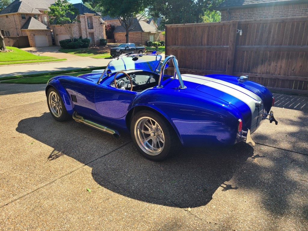
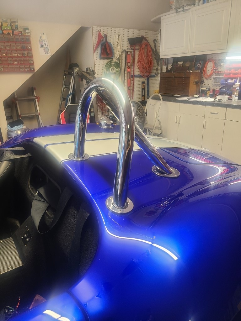
-
Post Thanks / Like - 0 Thanks, 1 Likes
-
Senior Member

Those are sexy. I considered it. I don't have a welder and ultimately it was more of unknown for me. Agree about the 1.5", I will also not have a Frankenstein bolt. There are a couple work arounds for it.
-
Senior Member

I don't have a TIG welder anymore but it wasn't hard to find someone with a portable one to weld this. The small amount of effort was worth it to me.
I had it chromed at a local plating shop.
-
Not sure if you're interested, but I have a set of mustang wheels with tires mounted from my build. I'm in Eastern Ohio, so with shipping not sure if it'd be worth it or not. Tried to PM you but it said your box was full.
-
Senior Member

Thanks man. I cleaned up my inbox. I can receive messages again. I’ll reach out.
-

Originally Posted by
Blitzboy54

Those are sexy. I considered it. I don't have a welder and ultimately it was more of unknown for me. Agree about the 1.5", I will also not have a Frankenstein bolt. There are a couple work arounds for it.
Lots of mobile welders that will come out to your house and not really expensive. I started out looking at the 2" bars, but then Jeff filled me in on the hassle to get those welded up and moved, so moved to the Breeze ones. Those Breeze bars with the recline and shorter base look awesome!
-
Senior Member

-
Senior Member

-
Senior Member

-
Cobra Driver

Nice!
Jesse,
Looking great! Can't wait to see it again. I'm pretty sure the Upstate Cobra's will be more than willing to come over and eat pizza too...
Mark III 4630RD Explorer 302, Holley SA570, FRPP B-cam, 4 to 4's, 3 Link, Bullitt wheels, Baer Brakes, 3.73 gears, HD T-5
Mark II Rebuilt into 1955 Jaguar D Type Replica Explorer 302, Holley SA670, Trick Flow Stage 1 cam, 3 Link 4.10 gears, Classic Gauges
PM me if you live in Upstate New York. Get added to the
"Upstate Cobras" email list. 60+ members!

-
Post Thanks / Like - 0 Thanks, 1 Likes
-
Senior Member

I’m always available for pizza
-
Post Thanks / Like - 0 Thanks, 1 Likes
-
Senior Member

I like the orange accents and the garage powder coating setup. I may look into doing something like that. I left most of my aluminum pieces natural, but there were a few metal parts I painted that would probably have been better off powdercoated. My seat brackets, sway bar mounts, etc. They are all parts that I can get to and remove fairly easily to recoat when needed, but powder coating is always the better option.
-
Post Thanks / Like - 1 Thanks, 0 Likes
-
Senior Member


Originally Posted by
JMD

I like the orange accents and the garage powder coating setup. I may look into doing something like that. I left most of my aluminum pieces natural, but there were a few metal parts I painted that would probably have been better off powdercoated. My seat brackets, sway bar mounts, etc. They are all parts that I can get to and remove fairly easily to recoat when needed, but powder coating is always the better option.
I powder coat almost everything. You're right it is better than paint and you can have some fun with it. The real reason for me is the NE gets muggy and the humidity eventually starts rusting uncoated steel parts.
-
Senior Member

-
Senior Member

I actually cut about a half inch off my lower steering shaft as well, but that was before I reverse the pillow bearing. Having done both there is plenty of room to remove and reinstall the lower shaft as needed without removing any other parts. There is no reason not to do this, and as far as I can tell as there is plenty of extra extension provided by the upper shaft. I also used my drill to dimple for every set screw, not just the one they tell you to in the manual. One little slip of any part of either shaft into the joint and no more steering. Helps me sleep better at night. Definitely an area you don't want to take any risks with.
-
Senior Member


Originally Posted by
JMD

I actually cut about a half inch off my lower steering shaft as well, but that was before I reverse the pillow bearing. Having done both there is plenty of room to remove and reinstall the lower shaft as needed without removing any other parts. There is no reason not to do this, and as far as I can tell as there is plenty of extra extension provided by the upper shaft. I also used my drill to dimple for every set screw, not just the one they tell you to in the manual. One little slip of any part of either shaft into the joint and no more steering. Helps me sleep better at night. Definitely an area you don't want to take any risks with.
That’s a good point. There is no reason not to do it. I’ll knock that out this weekend
-
Having a good start on your second build, how is it different from your first build in respect to how you are going about it?
-
Senior Member


Originally Posted by
Blitzboy54

Pedal Box
At the very least the metal sleeves need to com out. Also unless you want to cut the right side of the pedal too far you probably have to move the holes.
Which metal sleeves are you referring to? I'm close to this step and I'll need to not repeat these issues.
Thanks.
-
Senior Member


Originally Posted by
M22_COBRA

Which metal sleeves are you referring to? I'm close to this step and I'll need to not repeat these issues.
Thanks.
There are metal sleeves inside the bolt holes. In order to create enough wiggle room to make everything fit they have to be pulled out. At least they did in my case.
-
Senior Member


Originally Posted by
Namrups

Having a good start on your second build, how is it different from your first build in respect to how you are going about it?
That’s an interesting question. I’m spending a LOT less time micro researching everything. It’s early so it’s kinda like going through the motions in some ways. The IRS was fun since it’s new for me. Today was pretty cool because I have hit a point where I need to create something new.
On a side note my driveshaft arrived. That sucker is only like 8” long. The area I would put a safety loop is pretty tight. I’m going to have to figure something out.
-
Senior Member

-
Senior Member

Plan A
This is all well and good and honestly relieved I have an acceptable solution ready to go but what I really want is a clean tunnel and an electric brake. Like I said Estopp and the rest are great products but at the end of the day I need electric control of linear piston. I think I can figure something out. I have been poking around for solutions and I found this.
https://www.amazon.com/dp/B00NM8H5TG...fed_asin_title
It's generic linear actuator with built in limit switches and 2" of throw. It has 350 lbs of pull force (more than enough) and it was less than $40.
It arrived and worked as expected.
I installed it in a way that would allow me to test it without cutting the cables. I have no idea where I am going to end up so I would like to avoid doing something permanent. I wrapped the frame in a rag and used a worm clamp to secure it.
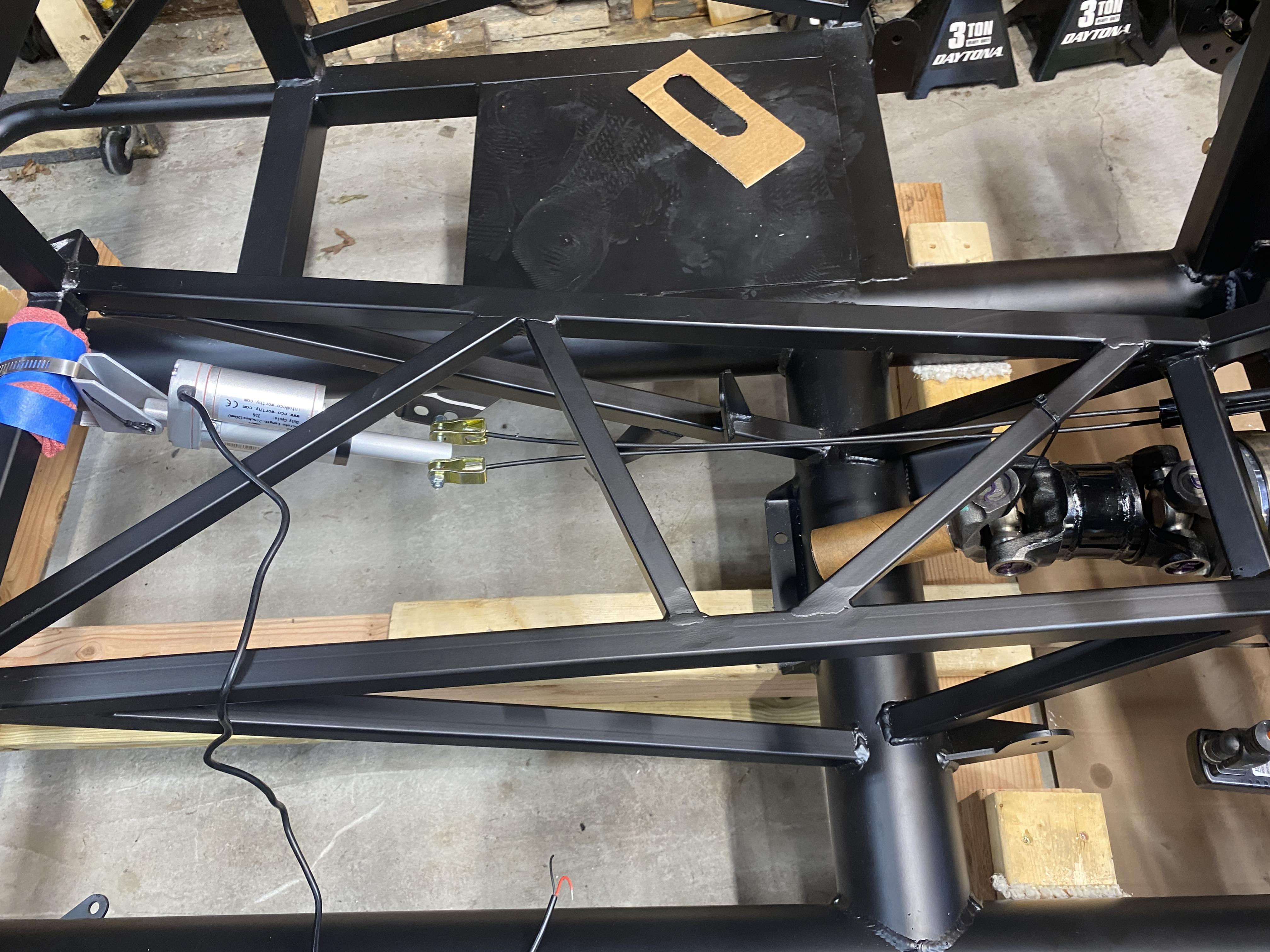
Last edited by Blitzboy54; 09-30-2024 at 12:34 PM.
-
Senior Member

After playing around it became obvious 2" is about an inch too much. I need to cut the throw in half. I have some ideas (one I am really excited about). In order to make the test below work I needed to put a lot of slack in it. There is plenty of room to attatch this unit on the underside of the original ebrake mount. I think I can get it pointing directly at the cable mounts.
Since it has built in limit switches I think a bi directional DC toggle switch is the plan. Hold in place until it stops. I would then use a separate 12v and put a proximity sensor on the shaft so when it's retracted and open it sends 12v to the parking brake light on the dash. Will run that trough a relay so it's only on when the car is on. Nothing is a done deal but I am very encouraged so far.
-
Senior Member

Super cool. I love the innovation and simplicity of this. I am a bit worried about my setup passing the HP inspection as I'm not using the stock handle (they don't work with my Gordon Levy wilwood brakes). I actually didn't want a handle at all and am using a ball valve fitting to hold pressure in the rear brake line. Technically it's not a separate braking system, but I'm hoping it gets through. If not I'll have to go to plan B...once I figure one out. But I like the idea of building something that can be engaged with a button. Will be following along and see what happens with yours. Good luck!
-
Senior Member


Originally Posted by
Blitzboy54

Plan B
One of the priorities for me on a second roadster was to do something different with the parking brake. I went with the stock setup last time and didn't love it. I am in the minority of folks when I say I actually really like the handle. It's a creative design and applies a lot of force to the parking brake. I just hated where it was. The original AC was right hand drive so naturally the parking brake would be on that side. Carol left it. Just like the shifter he came up with a creative inexpensive solution and ran with it. I respect the heck out of that but I think I can improve on it.
Now I am on a strict budget for this car. I am dangerously close to over budget at this point but "horseshoes and hand grenades" or some such. Estopp and Lokar make great products but both are expensive for what they are. So my goal is to either use parts that I already have in the kit or spend less than $100.
I started goofing around with the parking brake and came up with this. Under this arrangement using parts that are currently in the complete kit you can relocate the handle to the top of the cover.
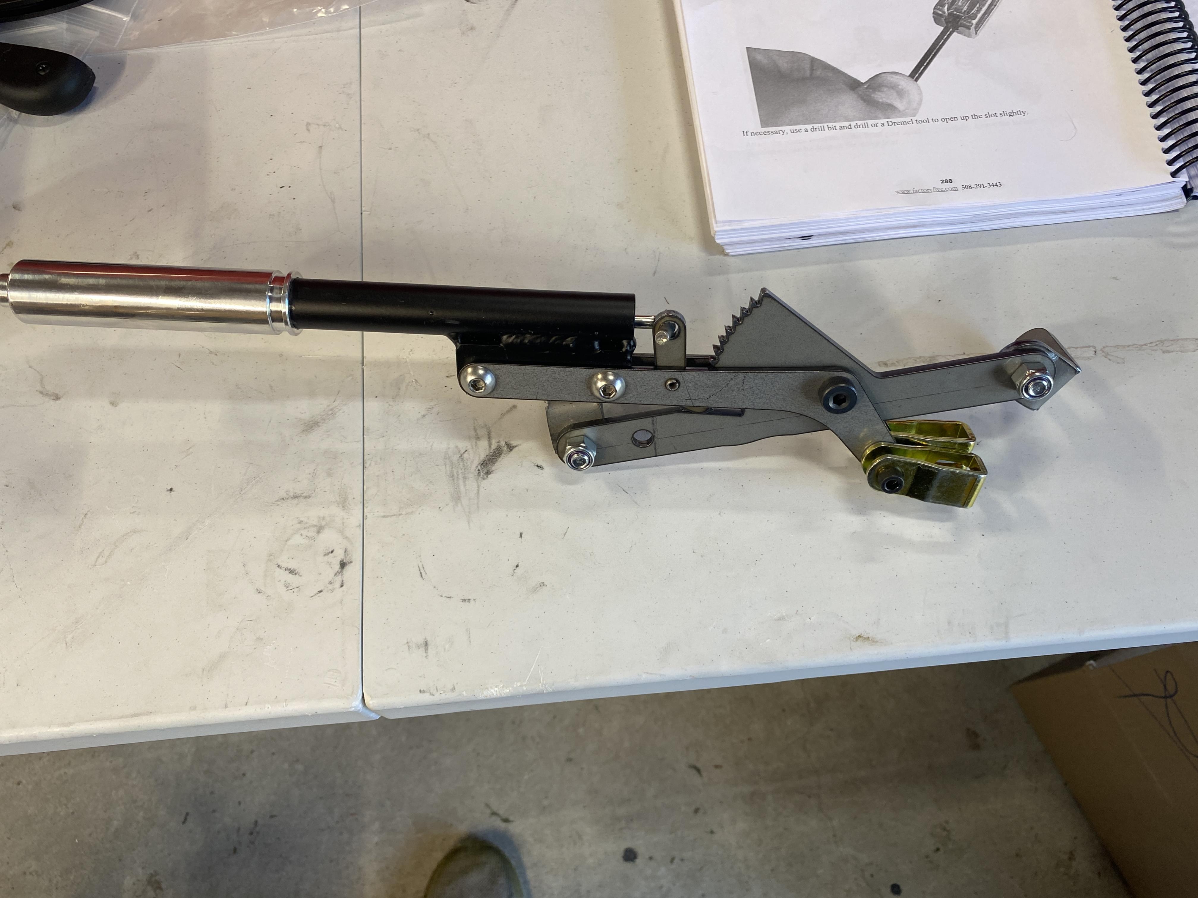
By lining up the mounts to behind the last support near the drive shaft couple and just under the upper transmission cover support you can put it on the passenger side on top of the tunnel. I would drill and use rivnuts with red locktite.
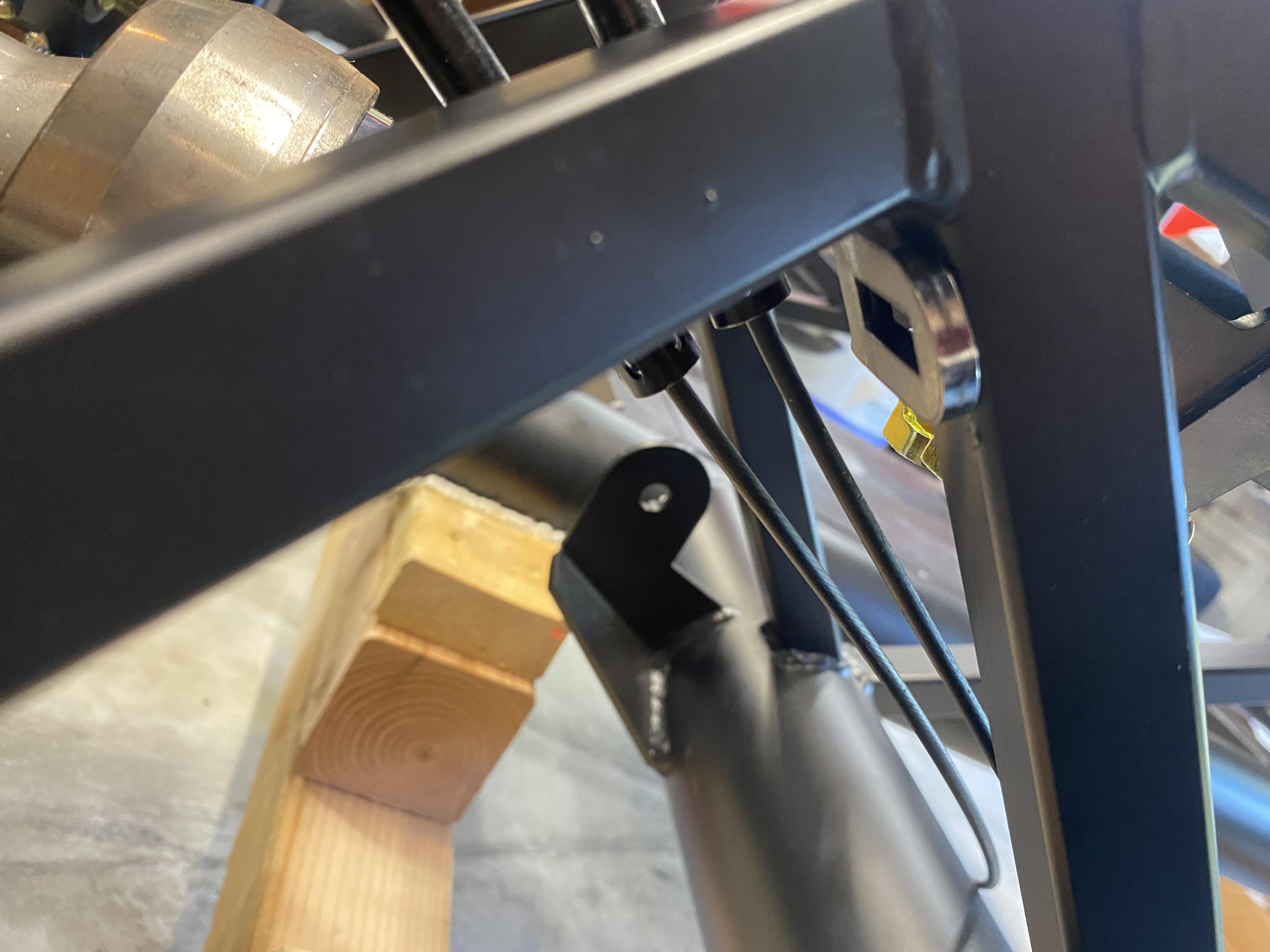
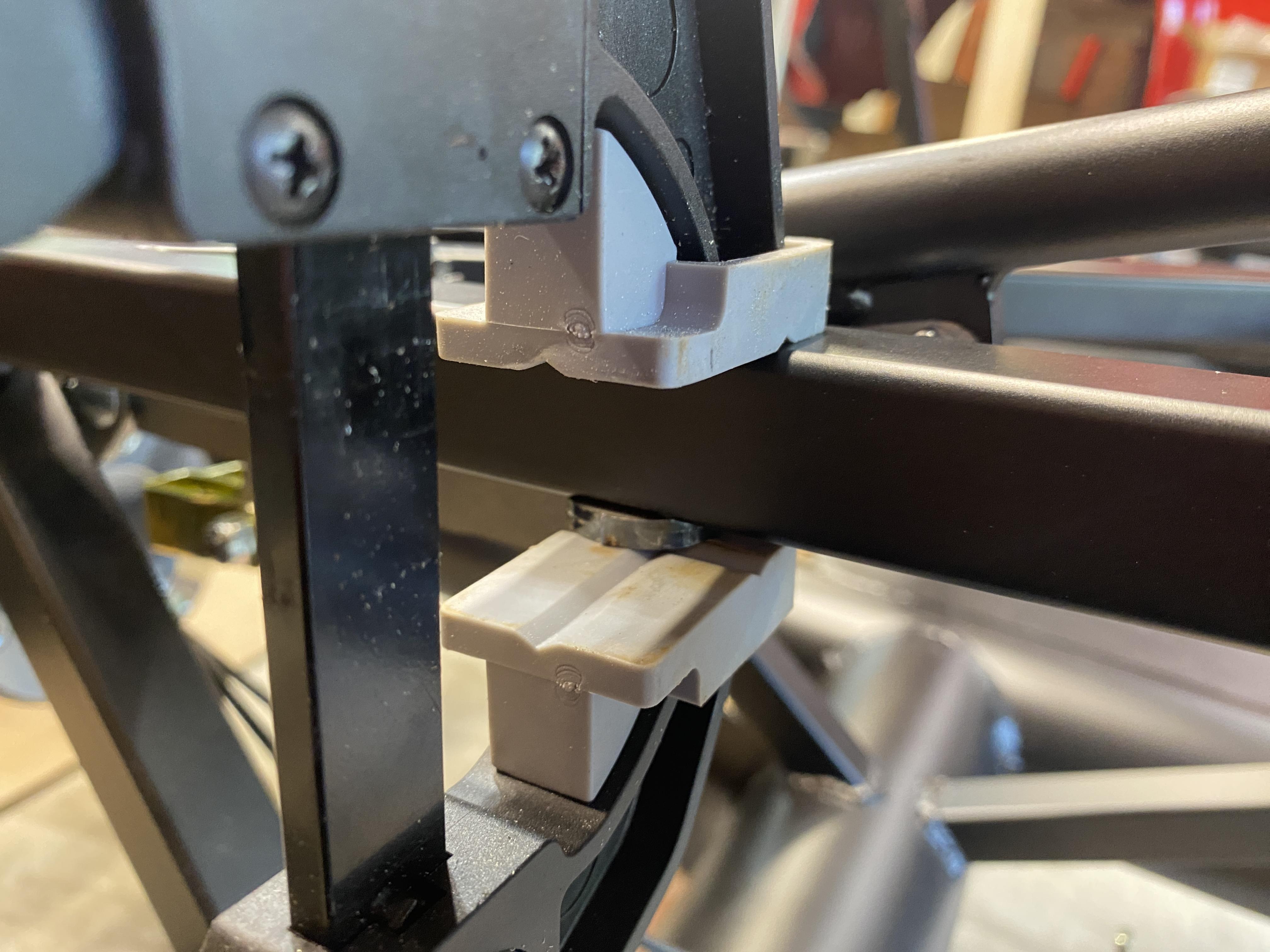
It would sit here. I later made a small adjustment to what you see here, also installed the driveshaft so I could judge clearance. I had to lower the rear mount by a cm to get the ratchet teeth below the trans cover. Most trim rings are between 5 and 5.25 inches so it has to be under. All things considered I almost called it here and started drilling.

My car is RHD. During the build process, I was worried that my knee might bang against the handbrake handle when driving. Honestly, it has never been an issue. So another option might be to move the lever to the left hand side of the trans tunnel?
Handbrake.jpg
cheers,
Nigel
Last edited by Nigel Allen; 09-16-2024 at 06:13 AM.
Mk.4 FFR supplied Right hand drive
Received 12/2012 completed 12/2019
Gen1 Coyote / TKO600 / IRS
Lots of mods to make compliant for Australian design rules
-
Senior Member


Originally Posted by
Blitzboy54

After playing around it became obvious 2" is about an inch too much. I need to cut the throw in half. I have some ideas (one I am really excited about). In order to make the test below work I needed to put a lot of slack in it. There is plenty of room to attatch this unit on the underside of the original ebrake mount. I think I can get it pointing directly at the cable mounts.
Since it has built in limit switches I think a bi directional DC toggle switch is the plan. Hold in place until it stops. I would then use a separate 12v and put a proximity sensor on the shaft so when it's retracted and open it sends 12v to the parking brake light on the dash. Will run that trough a relay so it's only on when the car is on. Nothing is a done deal but I am very encouraged so far.
Rather than relying on the limit switch to provide correct tension on the hand brake cables, you could use a current sensing relay to measure the motor current (torque) applied to the cables. This could be used to shut off the linear actuator. This way you would always have the correct tension applied to the brake cables. Something like this:
https://www.ebay.com.au/itm/22614957...CABEgLLq_D_BwE
I can help you with a wiring diagram if you like. I think it would be a cool solution.
Cheers,
Nige
Mk.4 FFR supplied Right hand drive
Received 12/2012 completed 12/2019
Gen1 Coyote / TKO600 / IRS
Lots of mods to make compliant for Australian design rules
-
Senior Member


Originally Posted by
Nigel Allen

Rather than relying on the limit switch to provide correct tension on the hand brake cables, you could use a current sensing relay to measure the motor current (torque) applied to the cables. This could be used to shut off the linear actuator. This way you would always have the correct tension applied to the brake cables. Something like this:
https://www.ebay.com.au/itm/22614957...CABEgLLq_D_BwE
I can help you with a wiring diagram if you like. I think it would be a cool solution.
Cheers,
Nige
Nigel,
This is a really cool idea. I have something similar in mind but a little lower tech. I am officially bumping your idea up. This is the new plan B and manual lever has been demoted to C.
As far as moving it to the drivers side I have a couple thoughts. First there is more room in the trans tunnel on that side as the driveshaft cheats to the right. The downside is I would have to cut and reeled the handle bracket and cable guide. The foot boxes are not symmetrical either. Itís an option.
-
Senior Member


Originally Posted by
Blitzboy54

Nigel,
This is a really cool idea. I have something similar in mind but a little lower tech. I am officially bumping your idea up. This is the new plan B and manual lever has been demoted to C.
As far as moving it to the drivers side I have a couple thoughts. First there is more room in the trans tunnel on that side as the driveshaft cheats to the right. The downside is I would have to cut and reeled the handle bracket and cable guide. The foot boxes are not symmetrical either. Itís an option.
It's bedtime down here, but I can sketch up the circuit I have in my head tomorrow morning. If I've got it right, in addition to the current sensor, you will only need a 5 pin automotive relay and a diode.
BTW, do you happen to know what the maximum current draw is on that actuator?
Cheers,
Nige
Last edited by Nigel Allen; 09-16-2024 at 07:36 AM.
Mk.4 FFR supplied Right hand drive
Received 12/2012 completed 12/2019
Gen1 Coyote / TKO600 / IRS
Lots of mods to make compliant for Australian design rules
-
One thing to keep in mind, my cables did streach a little after a season (about 1/2 inch). I had to re-adjust. I would also think about running your cables through a tube of some kind (PVC pipe maybe) to keep them from hanging when the tension is off. Great idea. I will put this on my future upgrade list on the coupe!
-
Senior Member


Originally Posted by
Namrups

One thing to keep in mind, my cables did streach a little after a season (about 1/2 inch). I had to re-adjust. I would also think about running your cables through a tube of some kind (PVC pipe maybe) to keep them from hanging when the tension is off. Great idea. I will put this on my future upgrade list on the coupe!
That was just a rough test. It will have an adjustable tentioner for sure.
-
Senior Member


Originally Posted by
Blitzboy54

That was just a rough test. It will have an adjustable tentioner for sure.
The sweet part of a current sensing relay, is it will automatically shut off when tension is correct, even if cables stretch/ pads wear.
Mk.4 FFR supplied Right hand drive
Received 12/2012 completed 12/2019
Gen1 Coyote / TKO600 / IRS
Lots of mods to make compliant for Australian design rules
-
Senior Member

Last edited by Blitzboy54; 09-30-2024 at 12:36 PM.
-
Senior Member

I used something like this: https://www.aliexpress.com/item/1005...e-b295129e7cdf
And it allows a single touch lock/unlock of the parking brake with a simple (on)-off-(on) rocker switch.
MK4, 427LS3, IRS, T56 Magnum, Wilwoods
-
Looking good! Do you have a source / part number for that spring? I'm using the same actuator and will be doing the same testing shortly.
-
I'm pretty sure that E-Stopp also uses a current sensing relay to control cable tension/travel. From their FAQ:
Q: How many inches of travel does the E-Stopp have?
A: About 2 inches. Most systems only need about 1. The motor stops itself once it reaches 600 pounds of resistance.
MkIV Roadster build: Gen 2 Coyote, IRS, TKO600. Ordered 10/24/18. Delivered 1/29/19. Engine installed 8/8/21. First start 9/12/21. First go-kart 9/17/21. Off to paint 4/11/22. Back from paint 12/30/22.
Build thread here.


 Thanks:
  Likes:


 Reply With Quote


