-
Senior Member


Originally Posted by
Kbl7td

The yoke will be diff from manual VS auto.
The dismantler description stated it came out of a manual transmission car so it should be "standard" to us.
-
Senior Member
Good news is the supplied adapter with my kit fits:
Adapter for Diff.jpg
I am going to go ahead and replace the half shaft seals as well. One appears to have been leaking but hard to tell since wrecking yards tend to get carried away with their pressure washing. I wouldn't think these would be leaking in a 2024 with 14K miles but I guess you never know. Either way, inexpensive "upgrade" and easy to do while on the bench.
-
Senior Member
I know this is probably a long shot but thought I would throw it out there. My used seats came with brackets for a C6. After comparing them to Corbeau's website it looks like they us a generic frame and then customize the locations of the risers to suit a given vehicle. I think I can make them work but here's my ask:
Can anyone provide feedback on how high the frame should be off the floor? These have rake to the rear and are about 2.5 inches high in the front and maybe 1 inch in the rear. I can cut and weld as needed, relocate the risers and make sure they bolt through the floor in the appropriate locations. The sliders are bolted tight to the seats and only add about 3/4" of overall height. Any feedback would be appreciated.
Seat Bracket.jpg
-
The back bottom of my Sparcos seats almost touch the floor. There is a balance between seeing over the dash and where your head lands relative to the side roll bar. I was trying to keep my head from hitting the side bar when sitting in them. I also had to cut some of the body, by the door, to get them to sit back far enough.
-
Senior Member
Originally Posted by
burchfieldb
The back bottom of my Sparcos seats almost touch the floor. There is a balance between seeing over the dash and where your head lands relative to the side roll bar. I was trying to keep my head from hitting the side bar when sitting in them. I also had to cut some of the body, by the door, to get them to sit back far enough.
Thanks for the response. I have reviewed Paul B's. build thread extensively and I think his seats are the same way. Essentially sitting flat on the floor and using the built in reclination of the seat instead of anything built into the mounting brackets. I think I may just cut the risers off the brackets and work backwards until I find the sweet spot. I am not sure where the seat will land in relation to the harness mounts either.
-
Senior Member
Making Some Progress
This is a bit of a hodge podge update. I am finally in the home stretch of my Triumph TR5T build. I committed to finishing this before becoming all consumed with the Coupe. Need to install the exhaust and plumb the fuel lines but probably ready for first start this week. A picture for proof and posterity:
Current Status.JPG
Now on to the Coupe! I actually installed my very first piece today with the steering rack. Pretty straightforward but a couple of comments. I am going to powdercoat the retainer bracket (along with many other pieces) but before I do so I am going to hollow out a half moon to clear the steering rack tube so it's not sawing on the sharp edge of the bracket for the next how ever many years:
Steering Bracket.jpg
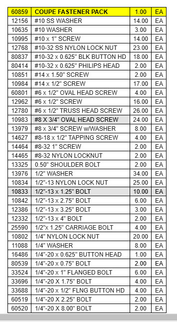
I also am curious if anyone is aware if there is a separate inventory sheet for this item:
Inventory List.jpg
I am asking because after searching twice, I was unable to locate 1/2" grade 8 washers and nuts for the steering rack bolts. Most of the other sub-boxes with multiple components had additional inventories but I couldn't find one for the hardware pack. So, off to Ace this morning and picked up the washers and nuts and loosely installed them. I also installed the zerks on the Moog tie rod ends a la edwardB but opted to not install the Energy Suspension boots since the Moog boots were quite well fastened on (maybe crimped with an internal wire?) and they were logoed so I stuck with them. For anyone interested, the zerks are 7 mm.
Moog Tie Rod Ends.jpg
And so there is actually proof I did something:
Steering Rack.jpg
Carry On!
Last edited by PNWTim; 01-28-2025 at 02:44 PM.
-
Post Thanks / Like - 0 Thanks, 3 Likes
-
Senior Member

Away you go! FYI, the Energy Suspension polyurethane boots will greatly outlast the rubber boots. Plus they're a lot stronger. Those are the reasons to switch them out. Your choice though.
Build 1: Mk3 Roadster #5125. Sold 11/08/2014.
Build 2: Mk4 Roadster #7750. Sold 04/10/2017.
Build Thread
Build 3: Mk4 Roadster 20th Anniversary #8674. Sold 09/07/2020.
Build Thread and
Video.
Build 4: Gen 3 Type 65 Coupe #59. Gen 3 Coyote. Legal 03/04/2020.
Build Thread and
Video
Build 5: 35 Hot Rod Truck #138. LS3 and 4L65E auto. Rcvd 01/05/2021. Legal 04/20/2023.
Build Thread. Sold 11/9/2023.
-
Senior Member
Originally Posted by
edwardb
Away you go! FYI, the Energy Suspension polyurethane boots will greatly outlast the rubber boots. Plus they're a lot stronger. Those are the reasons to switch them out. Your choice though.
I had every intention of doing so but the rubber boots are really anchored on there. I couldn't decide how aggressive to go with a screwdriver, etc. to remove them. I have the poly boots, just didn't install. I will take another look.
-
-
Senior Member
Originally Posted by
burchfieldb
Tim, these are the lists that I got from Dave at FFR.
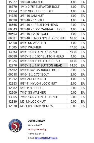
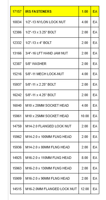
As for the tube on the steering rack, I was able to flex it enough to provide clearance without having to cut the bracket.
Good info, thanks. I don't think they actually include the 1/2" nuts and washers in grade 8. Although I doubt it matters, I am not a fan of mixing and matching grade 5 and 8 together. I was going to ask FF to send me the missing pieces but it looks like they supplied them, they are grade 5 (although the manual specifically states they are grade 8). Anyhow, no big deal and I appreciate the list for reference.
-
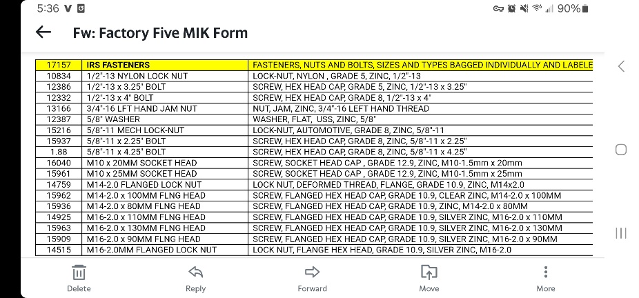
Forgot about this one, in case someone wants the bolt grades for the IRS fasteners. I agree, I do not like mixing the grades either. I ended up buying flange nuts, like they show in the manual. I was not a fan of the large fender washers and nylon lock nuts.
-
Post Thanks / Like - 0 Thanks, 1 Likes
-
Senior Member
Differential Install
Engaged in a 2 hour wrestling match today. Got it installed and have to say, nobody on this forum was exaggerating the difficulty of the process. So, so, tight but we got it done. I started the process by reaming out the front mounting ears. This reamer make it a piece of cake. I do think there is some possibility of making the holes off center if your not careful.
Diff with Reamer.jpg
Got it squeezed in and frankly was really confused over what hardware to use. I think I used the correct bolts but if I didn't I guess I can buy replacements. I do have one question though - the metal inserts for the front extend out of the poly bushings by about an 1/8th of an inch. I don't understand why this is so? They could easily be the correct length and still function correctly so if anyone knows the reason for this or if I did something wrong please let me know.
Diff Overhead.jpg
Close up of the bushing in question. Both sides are identical:
Bushing Pic.jpg
Last edited by PNWTim; 01-29-2025 at 10:56 PM.
-
Post Thanks / Like - 0 Thanks, 1 Likes
-
Senior Member
That gap is apparently normal. Many others have reported it and received feedback from FFR that it's OK. As you found out from installing the center section, it's a tight fit. Once bolted in place and all bolts to torque values, it's not going anywhere. My two IRS builders are from several years ago and didn't have that. But either FFR or Ford changed a bit since then. Not to worry.
Build 1: Mk3 Roadster #5125. Sold 11/08/2014.
Build 2: Mk4 Roadster #7750. Sold 04/10/2017.
Build Thread
Build 3: Mk4 Roadster 20th Anniversary #8674. Sold 09/07/2020.
Build Thread and
Video.
Build 4: Gen 3 Type 65 Coupe #59. Gen 3 Coyote. Legal 03/04/2020.
Build Thread and
Video
Build 5: 35 Hot Rod Truck #138. LS3 and 4L65E auto. Rcvd 01/05/2021. Legal 04/20/2023.
Build Thread. Sold 11/9/2023.
-
Senior Member

Mine is the same. The real disappointing news is if you have the rear sway bar - I just learned I must remove those lower IRS bolts again to install the sway bar mounts. Should be easier second time around - I hope.
I wish FFR would have made a note in the build manual regarding this. Also, the only instructions for installing the sway bars are on the Instructions page of the FFR parts page, and only for the Roadster, so you have to use those instructions for the Coupe sway bars.
Jim Phoenix
Coupe-R delivered 8/10/2024
289 USRRC, F5R1011063RD - delivered same day
Coupe-R has a Ford Performance 363 mated to a TKX, 18084.
Many details on my Coupe-R are different from a typical Coupe build because mine is not street legal, race only.
289 has a BP 302 mated to a TKX 18084.
"For a little more, you can do it yourself." - Ed Hollingsworth... 6-Pack forums
-
Senior Member

Originally Posted by
PNWTim
Close up of the bushing in question. Both sides are identical:
Bushing Pic.jpg
Both of my IRS builds have been like you showed. Like others noted above, I think you're good.
I couldn't agree more, it's a fight to get it up in there, especially if you're working solo (like yours truly). Congrats! One of your first milestones in the build completed!
Chris
Coupe complete kit. Index. Delivered: 4/22/24.
Build Thread. Coyote Gen 4X. T-56. IRS w/3.55. Wilwoods. PS. HVAC. Side windows.
MK4 Complete kit.
Build Thread Index. Delivered: 10/15/2020. Legal: 7/25/23. Coyote Gen3. TKO600 (0.64 OD). IRS w/3.55. PS. Wilwoods. Sway bars. This build is dedicated to my son, Benjamin.
Build Thread.
-
Post Thanks / Like - 1 Thanks, 0 Likes
-
Senior Member
Originally Posted by
Jphoenix
Mine is the same. The real disappointing news is if you have the rear sway bar - I just learned I must remove those lower IRS bolts again to install the sway bar mounts. Should be easier second time around - I hope.
I wish FFR would have made a note in the build manual regarding this. Also, the only instructions for installing the sway bars are on the Instructions page of the FFR parts page, and only for the Roadster, so you have to use those instructions for the Coupe sway bars.
Jim, thanks for the heads up. I actually opted for only a front sway bar based on feedback from a couple of coupe owners. I can honestly say, if I had to pull those lower bolts out to install it I would probably reconsider regardless. But you are correct, there should be a footnote or something in the manual that says "in the event you are.....".
-
Senior Member
Originally Posted by
460.465USMC
Both of my IRS builds have been like you showed. Like others noted above, I think you're good.
I couldn't agree more, it's a fight to get it up in there, especially if you're working solo (like yours truly). Congrats! One of your first milestones in the build completed!
It certainly felt like a milestone! I was lucky and had my son to help me so that was a blessing.
It's definitely one of those "a little bit up, a little bit forward, now a little bit down, now a little...".
-
Post Thanks / Like - 0 Thanks, 1 Likes
-
Senior Member
Originally Posted by
edwardb
That gap is apparently normal. Many others have reported it and received feedback from FFR that it's OK. As you found out from installing the center section, it's a tight fit. Once bolted in place and all bolts to torque values, it's not going anywhere. My two IRS builders are from several years ago and didn't have that. But either FFR or Ford changed a bit since then. Not to worry.
Thanks Paul. It's definitely not going anywhere, for sure. I just don't understand why the insert isn't simply flush. Such a basic thing and they are cutting those bushings so why would it be intentionally cut long? I am not an engineer but details like that baffle me.
-
Senior Member

Because you don’t want the bolt/washer on the rubber. It’s designed to be tight on the bushing. The bushing to rubber then is what gives it a tiny bit of flex.
-
Post Thanks / Like - 0 Thanks, 1 Likes
-
01-30-2025, 12:55 PM
#100
Mine is the same way also. If you ever have to do it again on your own, an engine hoist and some ratchet straps work well. I also used some ratchet straps between the back of the frame and the mounts to pull the rear mounts back some.
-
Post Thanks / Like - 1 Thanks, 0 Likes
-
01-30-2025, 08:14 PM
#101
Senior Member
Originally Posted by
PNWTim
Jim, thanks for the heads up. I actually opted for only a front sway bar based on feedback from a couple of coupe owners. I can honestly say, if I had to pull those lower bolts out to install it I would probably reconsider regardless. But you are correct, there should be a footnote or something in the manual that says "in the event you are.....".
My mistake, the sway bar mount actually goes through the lower control arm - the photo in the instructions is not very clear - but it becomes clear once under the car. Thank heaven I don't have to remove those IRS mount bolts!!
Jim Phoenix
Coupe-R delivered 8/10/2024
289 USRRC, F5R1011063RD - delivered same day
Coupe-R has a Ford Performance 363 mated to a TKX, 18084.
Many details on my Coupe-R are different from a typical Coupe build because mine is not street legal, race only.
289 has a BP 302 mated to a TKX 18084.
"For a little more, you can do it yourself." - Ed Hollingsworth... 6-Pack forums
-
Post Thanks / Like - 0 Thanks, 1 Likes
-
02-01-2025, 03:28 PM
#102
Senior Member
All Things Ball Joints
This post is a two parter - first is a question re: seating of the ball joint. I am using the Mevotech FF supplied ball joints and curious if this is as far as they thread in? They aren't threaded all the way to the top so I am assuming this is the case but if someone could please verify I would appreciate. Not sure if you can tell from the picture but the gap is about 3/32. The last 1/8" of the ball joint (towards the top) is unthreaded, smooth metal making it seem unlikely it would thread any further.
Ball Joint.jpg
Threaded in all the way - I think
Ball Joint Gap.jpg
And now to question(s) two. I know many on the forums opt to purchase the Howe Racing ball joints due to a real or perceived issue with threading in the Mevotech units. I like to try and use the supplied parts when it makes sense and in this case I thought it did. I was able to thread in the first one pretty much all the way by hand. No problem, piece of cake. But now on to the second one. 1 to 1 1/2 threads and full stop. No passing go, no collecting anything but barked knuckles. I chucked a wire brush in my Dremel and stripped all the powdercoat/paint from both the control arm and ball joint. Earned maybe an additional half turn. So, my questions are these: is this just ball joint roulette or is there a methodology to getting these things put together? I don't really want to spend $200 on the Howe units but I am also not going to fight these for several hours. If anyone has any insight, learnings or wisdom they can impart, I would greatly appreciate it.
-
02-01-2025, 06:19 PM
#103
Originally Posted by
PNWTim
This post is a two parter - first is a question re: seating of the ball joint. I am using the Mevotech FF supplied ball joints and curious if this is as far as they thread in? They aren't threaded all the way to the top so I am assuming this is the case but if someone could please verify I would appreciate. Not sure if you can tell from the picture but the gap is about 3/32. The last 1/8" of the ball joint (towards the top) is unthreaded, smooth metal making it seem unlikely it would thread any further.
Ball Joint.jpg
Threaded in all the way - I think
Ball Joint Gap.jpg
And now to question(s) two. I know many on the forums opt to purchase the Howe Racing ball joints due to a real or perceived issue with threading in the Mevotech units. I like to try and use the supplied parts when it makes sense and in this case I thought it did. I was able to thread in the first one pretty much all the way by hand. No problem, piece of cake. But now on to the second one. 1 to 1 1/2 threads and full stop. No passing go, no collecting anything but barked knuckles. I chucked a wire brush in my Dremel and stripped all the powdercoat/paint from both the control arm and ball joint. Earned maybe an additional half turn. So, my questions are these: is this just ball joint roulette or is there a methodology to getting these things put together? I don't really want to spend $200 on the Howe units but I am also not going to fight these for several hours. If anyone has any insight, learnings or wisdom they can impart, I would greatly appreciate it.
Mine seats all the way.
20240107_161438.jpg
I had to put the ball joint in the vice and use the arm to install and seat it, per FFR.
-
02-01-2025, 06:29 PM
#104
Senior Member
Originally Posted by
burchfieldb
Mine seats all the way.
20240107_161438.jpg
I had to put the ball joint in the vice and use the arm to install and seat it, per FFR.
Thanks. I just went back out to the shop and tried the freezer and heat. I got it halfway in but stopped dead. Guess I will keep trying. Might try swapping them side to side just to see if there is any difference.
-
02-02-2025, 12:33 PM
#105
I would reach out to FFR if you can't get it resolved. I am not sure of the root cause, maybe the threaded part gets distorted during welding? Do you have a machine shop close by?
-
02-02-2025, 01:31 PM
#106
Senior Member
Originally Posted by
burchfieldb
I would reach out to FFR if you can't get it resolved. I am not sure of the root cause, maybe the threaded part gets distorted during welding? Do you have a machine shop close by?
I am not sure what the issue is but it seems to be fairly arbitrary and random based on the threads I have read. One threaded nearly the entire way by hand, the other went one turn. If I had to guess, both are probably machined to pretty close tolerances with a plus or minus. If you end up with a male and female pair erring on the opposite ends of the ranges they won't go together. I had to walk away yesterday before I launched one over the fence but I am going to try swapping and see if I can split the difference.
Unfortunately, no machine shop close by. I will probably purchase Moog replacements for $40 if I can't get them to go today.
-
02-02-2025, 02:58 PM
#107
Originally Posted by
PNWTim
I am not sure what the issue is but it seems to be fairly arbitrary and random based on the threads I have read. One threaded nearly the entire way by hand, the other went one turn. If I had to guess, both are probably machined to pretty close tolerances with a plus or minus. If you end up with a male and female pair erring on the opposite ends of the ranges they won't go together. I had to walk away yesterday before I launched one over the fence but I am going to try swapping and see if I can split the difference.
Unfortunately, no machine shop close by. I will probably purchase Moog replacements for $40 if I can't get them to go today.
Lol, I know that feeling! Probably for the best if you can't get them to go in, it would likely may it easier to replace later on. I did use the recommend red loctite, maybe that added some lubrication to help it thread in and not bind.
-
Post Thanks / Like - 0 Thanks, 1 Likes
-
02-02-2025, 05:46 PM
#108
Senior Member
Out with the Old, in with the New
Trying for a quick win after losing the battle with the ball joints. Made a "crib" to support the hub out of 1" black pipe while I drove out the studs. I had intended to press them out with my vise but that was a non-starter for me. Supported the hub on the back anvil of the vice and after a couple sharp raps they popped right out.
Old Studs Hub.jpg
Ran the new studs in using a couple of extra thick grade 8 washers, grease and two lugs nuts
New Studs Hub.jpg
Not terribly exciting but progress is progress.
-
Post Thanks / Like - 0 Thanks, 1 Likes
-
02-02-2025, 07:35 PM
#109
Originally Posted by
PNWTim
This post is a two parter - first is a question re: seating of the ball joint. I am using the Mevotech FF supplied ball joints and curious if this is as far as they thread in? They aren't threaded all the way to the top so I am assuming this is the case but if someone could please verify I would appreciate. Not sure if you can tell from the picture but the gap is about 3/32. The last 1/8" of the ball joint (towards the top) is unthreaded, smooth metal making it seem unlikely it would thread any further.
Ball Joint.jpg
Threaded in all the way - I think
Ball Joint Gap.jpg
And now to question(s) two. I know many on the forums opt to purchase the Howe Racing ball joints due to a real or perceived issue with threading in the Mevotech units. I like to try and use the supplied parts when it makes sense and in this case I thought it did. I was able to thread in the first one pretty much all the way by hand. No problem, piece of cake. But now on to the second one. 1 to 1 1/2 threads and full stop. No passing go, no collecting anything but barked knuckles. I chucked a wire brush in my Dremel and stripped all the powdercoat/paint from both the control arm and ball joint. Earned maybe an additional half turn. So, my questions are these: is this just ball joint roulette or is there a methodology to getting these things put together? I don't really want to spend $200 on the Howe units but I am also not going to fight these for several hours. If anyone has any insight, learnings or wisdom they can impart, I would greatly appreciate it.
Before I installed the driver side ball joint I set up a wire brush in a drill to completely remove powder coating from male and female threads. I put red loctite on the threads and started threading the ball joint. It did not just thread right in by hand. Loaded the control arm in the vise and tightened it with a BA wrench until it would not turn. It looked exactly like your unseated ball joint. I was as frustrated as you and went back to work on other shop projects. I needed the drill. I grabbed the drill and realized the new wire brush still looked new. The parts had not been wire brushed and I drove the coating power (coating flakes) into the female threads either galling the thread or creating a thickened red loctite bond. My wife would call that senior moment,"slippage" (:-)
I bought another control arm and ball joint from FFR fearing the part was toast. They're down the road and it was a good excuse to visit. Wire brushing the ball joint and control arm allowed the ball joints to twist in with minimal effort.
I purchased a tool a few years ago to remove rusted bolts, Solary induction heater. I put the "damaged" control arm in the vise and wrapped the supplied element around the ball joint and heated it until it started to smoke. That thing actually came out with a bit of effort. Both ball joint and control arm threads were toast.
Last edited by Peter Ross; 02-02-2025 at 07:39 PM.
-
Post Thanks / Like - 1 Thanks, 0 Likes
-
02-02-2025, 10:44 PM
#110
Senior Member
Originally Posted by
Peter Ross
Before I installed the driver side ball joint I set up a wire brush in a drill to completely remove powder coating from male and female threads. I put red loctite on the threads and started threading the ball joint. It did not just thread right in by hand. Loaded the control arm in the vise and tightened it with a BA wrench until it would not turn. It looked exactly like your unseated ball joint. I was as frustrated as you and went back to work on other shop projects. I needed the drill. I grabbed the drill and realized the new wire brush still looked new. The parts had not been wire brushed and I drove the coating power (coating flakes) into the female threads either galling the thread or creating a thickened red loctite bond. My wife would call that senior moment,"slippage" (:-)
I bought another control arm and ball joint from FFR fearing the part was toast. They're down the road and it was a good excuse to visit. Wire brushing the ball joint and control arm allowed the ball joints to twist in with minimal effort.
I purchased a tool a few years ago to remove rusted bolts, Solary induction heater. I put the "damaged" control arm in the vise and wrapped the supplied element around the ball joint and heated it until it started to smoke. That thing actually came out with a bit of effort. Both ball joint and control arm threads were toast.
Thanks Peter. I ordered replacement Moog ball joints today. There are certain things I am willing to futz with but with the track record these things have I just decided I was done with it. I did try switching them side to side this morning but it didn't make any difference. Kind of bummed because I paid for the darn things but I am a firm believer new parts should not go together with this kind of difficulty. I will be very curious to see if the replacements thread right in - I will know Wednesday and report back.
-
Senior Member
That's a bummer, Tim. I've read about builders encountering this issue for a few years now. Somehow, they went in fairly well on both my builds. But, I did have to use some leverage. I hope your replacements thread right in without a battle.
Chris
Coupe complete kit. Index. Delivered: 4/22/24.
Build Thread. Coyote Gen 4X. T-56. IRS w/3.55. Wilwoods. PS. HVAC. Side windows.
MK4 Complete kit.
Build Thread Index. Delivered: 10/15/2020. Legal: 7/25/23. Coyote Gen3. TKO600 (0.64 OD). IRS w/3.55. PS. Wilwoods. Sway bars. This build is dedicated to my son, Benjamin.
Build Thread.
-
Senior Member
Originally Posted by
460.465USMC
That's a bummer, Tim. I've read about builders encountering this issue for a few years now. Somehow, they went in fairly well on both my builds. But, I did have to use some leverage. I hope your replacements thread right in without a battle.
I know, kind of annoying. I kind of felt like I gave it the old college try too, but no dice. I received the Moog replacements yesterday and they threaded right in so go figure. Like I said previously, seems there is a little "ball joint roulette" going on and I landed on green 00. I even used Erik Treves' technique of freezer on the ball joint and heat gun on the control arm but still didn't cooperate. In the rear view mirror now so moving on. Really enjoying the suspension work, it's like a big erector set (dating myself I know).


 Thanks:
  Likes:


 Reply With Quote
