
Visit our community sponsor

Thanks:
0

Likes:
0
-
Senior Member

How do you know intercooler is effective? MAX temp?
I've been reading everything there is on this forum about the intercooler (818 specific).
It seems like the stock air to air system on the 818 may not be sufficient.
The consensus on this forum seems to be an Air to Water system would be most effective.
I thought I read some where that the FFR red car was using an AWIC and the Blue car has an AAIC.
ASSUMING THE TEMPERATURE GAUGE IS CORRECT: On the latest video from FFR it shows that the motor failed when the inlet temperature was ~ 270! ( I assume degrees F)
At the beginning of the straight section of track the inlet temperature was ~140 (at 4:23 on video) by the end of the WOT run it was at 230. These temperatures seem high to me, are they? What is typical? This thread said "279°F, holy crap that's hot! "
So I'll put in a gauge for post intercooler inlet air temperature. But what is a high number?
And if the computer sees such a high temperature, shouldn't the computer compensate and de-tune itself?
-
The computer doesn't see those temps. It reads air intake temp pre turbo, not post.
-
Senior Member

based on the rapid changes in temperature shown, I am curious if FFR added an inlet air temperature sensor post turbo/pre IC (???) and that is what was showing up on the monitor.
-
Senior Member

Originally Posted by
billjr212

based on the rapid changes in temperature shown, I am curious if FFR added an inlet air temperature sensor post turbo/pre IC (???) and that is what was showing up on the monitor.
What would the purpose of after turbo and before intercooler be? Maybe turbo efficiency?
I don't think the temperature is pre IC, based on the temperature trend. It starts off cool at the beginning of the run, then progressively climbs up to the ultimate end of the run. Temp was 99 at Oak Tree (?) turn on first lap then 140 on second lap, same place. If it was post turbo/pre IC it would be the same over time, with no heat soak. Right?
-
Director of R&D, FFR

Remember the boost spiked to 44psi so the crazy high numbers at the end of the video are not from ordinary engine running. Not only was the boost high but the engine was not mapped for it so it was likely running way lean as well.
Jim Schenck
Factory Five Racing
-
Senior Member

After we disassembled the car and got a closer look, we found that the red 818R had an oil leak onto the exhaust manifold that burned the timing chain cover and the hose to the external waste gate. With the hose melted, the boost spiked to 45 PSI and the engine threw a connecting rod. The engine was shut down and John coasted to a stop on the front straight away. The damage was too much to continue.[/QUOTE]
Jim, was the oil leak what caused the bad chain of events? Sorry don't mean to hijack this thread.
-
Director of R&D, FFR
It was hard to tell with the cover so burned. I think it was somewhere that was crankcase related and not in the pressure system since it didn't show up during all the dyno pulls we did but once the car started sloshing the oil around it started leaking. Also once the top of the block cracked there was oil everywhere making it hard to track. We had shields on the manifold on both sides but not in the middle and that is where the cover was burned so something ran down the front or inside the timing cover right near the middle. I would suspect power steering fluid from the location but the level in the tank was unchanged and the lines were dry coming out of the pump.
Jim Schenck
Factory Five Racing
-
Senior Member
Originally Posted by
Jim Schenck
It was hard to tell with the cover so burned. I think it was somewhere that was crankcase related and not in the pressure system since it didn't show up during all the dyno pulls we did but once the car started sloshing the oil around it started leaking. Also once the top of the block cracked there was oil everywhere making it hard to track. We had shields on the manifold on both sides but not in the middle and that is where the cover was burned so something ran down the front or inside the timing cover right near the middle. I would suspect power steering fluid from the location but the level in the tank was unchanged and the lines were dry coming out of the pump.
Thanks Jim, I didn't know the red 818R had power steering. We're all rooting for you to get the car fixed and back out on the track.
-
818 builder

For the boost to spike so high the ecu must of not been tuned with a fuel or boost cut to save it. Its a tuff pill the swallow cause these cars are just so cool.
818S frame #13 Jdm version 8 ej207
-
Even when the boost was (I'm assuming) normal around 24 psi, the IAT reach ~ 210-220 degrees. That has to be post intercooler temps. When Wayne said, "279°F, holy crap that's hot!", he was referring to my PRE intercooler, post turbo temperatures. Watching this video makes me feel a little better about my ~180-190 post intercooler temperatures that I was seeing with my AWIC. Since I've switched back to an air-air intercooler, we'll find out how that works this weekend (on track).
This is also assuming that Factory Five is running a Speed Density tune on their car. That's when the ECU needs to see actual intake (manifold) temperatures. There IS a compensation table that will pull timing based on that temperature. But, that alone isn't enough to prevent a catastrophic failure of a 20+ psi overboost condition. There's also a "boost cut" threshold that can cut timing/fuel based such an event.
818S - #67 (SOLD IT!)
Delivered: 18 November 2013
Go Karted: 29 December 2013
Titled/Registered: 28 March 2014
Finished: NEVER!
341 hp @ 4844 RPM / 389 tq @ 3717 RPM
-
818 builder
Originally Posted by
JeromeS13
Even when the boost was (I'm assuming) normal around 24 psi, the IAT reach ~ 210-220 degrees. That has to be post intercooler temps. When Wayne said, "279°F, holy crap that's hot!", he was referring to my PRE intercooler, post turbo temperatures. Watching this video makes me feel a little better about my ~180-190 post intercooler temperatures that I was seeing with my AWIC. Since I've switched back to an air-air intercooler, we'll find out how that works this weekend (on track).
This is also assuming that Factory Five is running a Speed Density tune on their car. That's when the ECU needs to see actual intake (manifold) temperatures. There IS a compensation table that will pull timing based on that temperature. But, that alone isn't enough to prevent a catastrophic failure of a 20+ psi overboost condition. There's also a "boost cut" threshold that can cut timing/fuel based such an event.
I am guessing there was not boost cut set into there setup. I also think the awic will prove to work the best through your testing unless you can get large amounts of air pressure to the AAIC.
Last edited by metalmaker12; 10-07-2014 at 07:38 PM.
818S frame #13 Jdm version 8 ej207
-
Research Calibrator

Originally Posted by
matteo92065
it shows that the motor failed when the inlet temperature was ~ 270! ( I assume degrees F)
At the beginning of the straight section of track the inlet temperature was ~140 (at 4:23 on video) by the end of the WOT run it was at 230. These temperatures seem high to me, are they? What is typical?
So I'll put in a gauge for post intercooler inlet air temperature. But what is a high number?
And if the computer sees such a high temperature, shouldn't the computer compensate and de-tune itself?
Typical measurements of turbocharger compressed air *before* the intercooler could easily be in the 250-300 degrees F range.
Here is an example taken from an EVO of a friend of mine:

You can see the air temps pre intercooler (post turbo)*green* peak around 250 degrees F. Air temps after the intercooler peak *red* at 83 degrees F. That is a very efficient and large core with very good airflow over it (front mount with templates).
Alternatively I have seen some top mounts have temperatures above 250 degrees after the intercooler. Top mounts are very hard to get right.
Originally Posted by
Mechie3
The computer doesn't see those temps. It reads air intake temp pre turbo, not post.
The default configuration on the Subaru platform is to read IATs pre turbo, usually inside the MAF sensor housing. For any Subaru with any amount of modifications one of the first mods should be to put an IAT *post* intercooler, and change the ECM calibration to match. Trivial to do, and can make a huge difference in engine safety. A new IAT costs $30, and a new engine $3000, so there is no excuse not to.
Originally Posted by
matteo92065
What would the purpose of after turbo and before intercooler be? Maybe turbo efficiency?
I don't think the temperature is pre IC, based on the temperature trend. It starts off cool at the beginning of the run, then progressively climbs up to the ultimate end of the run. Temp was 99 at Oak Tree (?) turn on first lap then 140 on second lap, same place. If it was post turbo/pre IC it would be the same over time, with no heat soak. Right?
Correct.. On my 08 STI, I have pre turbo, post turbo pre intercooler, and post intercooler. I use it for data collection in regards to turbo performance ( I also measure pressure at all three locations ). As far as the ECU is concerned, the last one is the one that counts.
Originally Posted by
Jim Schenck
Remember the boost spiked to 44psi so the crazy high numbers at the end of the video are not from ordinary engine running. Not only was the boost high but the engine was not mapped for it so it was likely running way lean as well.
You should never ever have a car with no boost limiter installed. That is just asking for throw away money. If the stock MAP sensor can’t read high enough, spend the $90 to get a 5 bar sensor and adjust accordingly. Boost cut is there for a reason, and a melted wastegate hose is that reason. [ note I speak from experience having done this exact mistake a number of times.. including destroying a few engines. I like my collection of ‘I am a dumbass’ engine blocks. ]
Originally Posted by
JeromeS13
Even when the boost was (I'm assuming) normal around 24 psi, the IAT reach ~ 210-220 degrees. That has to be post intercooler temps. When Wayne said, "279°F, holy crap that's hot!", he was referring to my PRE intercooler, post turbo temperatures. Watching this video makes me feel a little better about my ~180-190 post intercooler temperatures that I was seeing with my AWIC. Since I've switched back to an air-air intercooler, we'll find out how that works this weekend (on track).
This is also assuming that Factory Five is running a Speed Density tune on their car. That's when the ECU needs to see actual intake (manifold) temperatures. There IS a compensation table that will pull timing based on that temperature. But, that alone isn't enough to prevent a catastrophic failure of a 20+ psi overboost condition. There's also a "boost cut" threshold that can cut timing/fuel based such an event.
While 180-190 degrees is not uncommon, I would not like it. The 1700 whp GT-R running at TX2K last year had post intercooler temps in the mid 130s-140s, and that was at 40psi of boost. In my 08 STI with an EFR7670 at 26psi my IATs post intercooler are infrequently over 110 degrees when it is 70 degrees ambient. Again large FMIC with good airflow.
Originally Posted by
metalmaker12
I am guessing there was not boost cut set into there setup. I also think the awic will prove to work the best through your testing unless you can get large amounts of air pressure to the AAIC.
Agreed. Intercoolers only work with LOTS of airflow.. and it has to actually go across the intercooler. If you don’t have ducting to direct the air into the core, it will go around it.
Jeff
Last edited by sponaugle; 10-08-2014 at 03:02 PM.
-
Moonlight Performance


Great info Jeff.
What kind of boost-limiting failsafe devices are suggested? I've read about mechanical devices that have an adjustable spring tension in them that simply vent manifold pressure to atmosphere above whatever pressure you set them to, but these really don't seem to be widely used....... or is it that they should be but aren't?
-
818 builder
Originally Posted by
Hindsight
Great info Jeff.
What kind of boost-limiting failsafe devices are suggested? I've read about mechanical devices that have an adjustable spring tension in them that simply vent manifold pressure to atmosphere above whatever pressure you set them to, but these really don't seem to be widely used....... or is it that they should be but aren't?
You can set it into the ecu, oem and aftermarket setups all have them. Factory five did not have it set into the tune , I am unsure why, but that's all you really need to be safe. It works off the map sensor and sends info to ecu to cut boost and fuel. I have really never seen the manuel one in operation on a subie, because there is really no need if you tune it right.
818S frame #13 Jdm version 8 ej207
-
Moonlight Performance
Thanks MetalMaker. And is there no situation in which the ECU would not receive the inputs it needs to make that happen? Some sort of partial leak on the manifold pressure sensor that causes some pressure, but not full pressure to be shown to the ECU?
-
Research Calibrator
Originally Posted by
metalmaker12
You can set it into the ecu, oem and aftermarket setups all have them. Factory five did not have it set into the tune , I am unsure why, but that's all you really need to be safe. It works off the map sensor and sends info to ecu to cut boost and fuel. I have really never seen the manual one in operation on a subie, because there is really no need if you tune it right.
Yep.. pretty much all ECUs have some kind of boost cut if they support boosted applications from the factory. Some ECUs for NA cars don't have this feature however.
Originally Posted by
Hindsight
Thanks MetalMaker. And is there no situation in which the ECU would not receive the inputs it needs to make that happen? Some sort of partial leak on the manifold pressure sensor that causes some pressure, but not full pressure to be shown to the ECU?
The most common reason boost cut gets disabled is when boost levels are beyond the factory sensor (which in the older cars is around 23-24psi). If the sensor can't read any higher, you have to disable the boost cut. This is a bad idea, and instead you should upgrade the sensor. * UPDATE * By the way I didn't mean to imply something bad about the FFR guys. I made the same mistake a number of times, and blew up some engines in a spectacularly way. It is all in the fun.
While it is possible to have a failure in the boost sensor, in most cases the sensor is installed directly in the manifold. If you have a broken manifold you will have lots of other problems.
Jeff
Last edited by sponaugle; 10-08-2014 at 04:39 PM.
-
Moonlight Performance
-
Director of R&D, FFR
The red car is running an aftermarket ECU which we were data logging through the Racepak but also we have a second sensor on the intake for a direct boost reading. (only because the Electromotive to Racepak cable wasn't available the last time we ran) The output on the video is from the racepak sensor which shows the boost and vaccum correctly but when we looked at the data log of the ECU sensor (a GM style MAP) it is flatlined at zero. My first thought was that the signal line also popped off but it was still clamped in place so my next guess is either a sensor failure or something not working in the data logging, however the coolant temp is also pulled directly from the serial output of the ECU so I would be surprised if only one of the data streams was not working. On the dyno at the tuner's shop the ECU sensor was reading and showed up on his laptop but the racepak only logs once the GPS hits a certain speed so we don't have that to see if it was working. I can't imagine the engine would even run if the sensor was completely dead as it is such a critical part of the system but still it is posible something was not right with it which might also explain why the intake temps were also so much higher than on the dyno. (we also added a holding tank to the sytem post dyno so we were expecting lower temps and longer warm up time but neither was true)
Also no offense taken on trying to decipher the problem and prevent it from happening again, that is exactly what we are trying to do as well and if it helps other people not have the same issue than that is part of why we race the car in the first place.
Jim Schenck
Factory Five Racing
-
Research Calibrator
Originally Posted by
Jim Schenck
The red car is running an aftermarket ECU which we were data logging through the Racepak but also we have a second sensor on the intake for a direct boost reading. (only because the Electromotive to Racepak cable wasn't available the last time we ran) The output on the video is from the racepak sensor which shows the boost and vacuum correctly but when we looked at the data log of the ECU sensor (a GM style MAP) it is flatlined at zero. My first thought was that the signal line also popped off but it was still clamped in place so my next guess is either a sensor failure or something not working in the data logging, however the coolant temp is also pulled directly from the serial output of the ECU so I would be surprised if only one of the data streams was not working. On the dyno at the tuner's shop the ECU sensor was reading and showed up on his laptop but the racepak only logs once the GPS hits a certain speed so we don't have that to see if it was working. I can't imagine the engine would even run if the sensor was completely dead as it is such a critical part of the system but still it is possible something was not right with it which might also explain why the intake temps were also so much higher than on the dyno. (we also added a holding tank to the system post dyno so we were expecting lower temps and longer warm up time but neither was true)
Also no offense taken on trying to decipher the problem and prevent it from happening again, that is exactly what we are trying to do as well and if it helps other people not have the same issue than that is part of why we race the car in the first place.
Very cool Jim. I didn't know that was an aftermarket ECU. I assume from the first sentence it is an electromotive?
It is a great idea to have a separate boost sensor for the Racepak, and in this case it really helped as you could see the actual boost. I am surprised to motor lasted as long as it did at those boost levels. You got thru a couple of gears before it really let go! Most aftermarket ECUs are speed density based, so they would depend on the MAP sensor working... so perhaps it was just a logging issue. It might also be helpful to datalog AFR and fuel pressure in the racepak if you can.
I am curious what temperature sensor the racepak is using for intake air temp (post intercooler I assume)? Is that a standard GM/Delco 3/8 NPT IAT sensor? I am putting VCPs A2W in my EZ30R 818, so I am interested to see other peoples results. I am installing temperature sensors both pre and post intercooler, ambient, and pre/post water (AWIC water) flows. I hope that will help in determining the amount of heatsoak and latent energy in the system.
Cheers,
Jeff
-
Director of R&D, FFR
Jeff,
We do log fuel pressure and Air Fuel and really any sensor inputs the ECU has (it is Electromotive) we log by default due to the serial connection with the racepak. The air temp sensor is that GM NPT threaded one and it is in the elbow between the intercooler and throttle body. We also have a spare coolant temp sensor, now that we log temp direct from the ECU, so that was going to go in the AWIC water, however I am not sure we aren't going to go back to air to air. After we put the turbo blanket on the blue car our heat soak issue from Watkins Glen didn't show up at VIR in July so we may try and go back to that path, but possibly with meth injection added as well. Nothing has been decided yet for sure other than the AWIC we had (not a VCP) was defintely not working well enough since the warning light came on 4 turns into the warm up lap on a relatively cool day. Also I am very big on lightweight above all else and carrying around all that water pains me deeply.
Jim Schenck
Factory Five Racing
-
Research Calibrator
Originally Posted by
Jim Schenck
Jeff,
We do log fuel pressure and Air Fuel and really any sensor inputs the ECU has (it is Electromotive) we log by default due to the serial connection with the racepak. The air temp sensor is that GM NPT threaded one and it is in the elbow between the intercooler and throttle body. We also have a spare coolant temp sensor, now that we log temp direct from the ECU, so that was going to go in the AWIC water, however I am not sure we aren't going to go back to air to air. After we put the turbo blanket on the blue car our heat soak issue from Watkins Glen didn't show up at VIR in July so we may try and go back to that path, but possibly with meth injection added as well. Nothing has been decided yet for sure other than the AWIC we had (not a VCP) was defintely not working well enough since the warning light came on 4 turns into the warm up lap on a relatively cool day. Also I am very big on lightweight above all else and carrying around all that water pains me deeply.
Great stuff Jim. Ah so that temp was post intercooler. Those are pretty warm temps for sure. I assume you have a pretty large air to water heat exchanger in the front of the radiator?
I have done a lot of water and meth injection over the years on the Subaru platform. I did some experiments with injecting water/meth before and after the intercooler (Subaru) and the results seemed to indicate that after the intercooler worked better if the intercooler was operating efficiently, but spraying before the intercooler had better overall gain if the intercooler was running very hot. The only downside to using a water/methanol injection is being able to detect a failure in the system. If you really tune for the water/methanol spray aggressively you need a good windowing flow sensor (so you can detect a broken/open line, or a clogged jet/bad pump). The Aquamist stuff works well for that case, and you can use it to cut boost. On the H6 SEMA STI that Jeff Perrin built he did an Aquamist system that did sprays both before the intercooler and after.
Given the HP output I am building for I will probably face a similar issue. Lots of heat and nowhere to go.
I'm happy to see how hard you guys are pushing the cars. Watching the video shows how well the car performs.
Jeff
-
Moonlight Performance
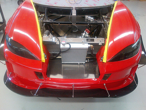
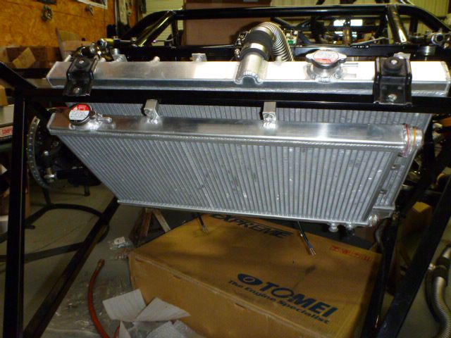
From the pics I saw, the AWIC heat exchanger on the FF track car is small and there is no ducting to prevent air from bypassing it and taking the path of least resistance, going around the exchanger to get to the radiator. It's also a really thick core as well which, I think, compounds that issue.
See pic here: http://thefactoryfiveforum.com/conte...rogress-Report
You can get thinner AWIC exchangers that are nearly the same size as the engine radiator. This would ensure you get enough flow and cooling. I'm convinced a setup with an exchanger like that will work great, and I base it off Wayne's results since his has a large, thin heat exchanger as well (10 dyno pulls with basically no increase in temps... and I'm sure that's just with a big fan blowing air on the car 5 or so feet in front of the car while on the dyno - on a track you'd get even better cooling due to much more air flow).
As for the added weight... no argument from me there. It's definitely a problem. But I'll be really interested to see if you guys can get an A2A performing well with 400hp worth of boost.
I hope you guys aren't too discouraged with what happened. All of us here are very excited to see what you guys can do with these track cars once properly sorted out. Don't give up!
-
Senior Member

Really interesting discussion. With builds like this (ie 400 hp and above) I imagine that above all else airflow to the A2A intercooler is going to be the limiting factor...you can certainly get a core that can handle it, but is there enough airflow. Really cool to hear from Jim that improved thermal management (ie turbo blanket) made such a big difference in heat soak. A2W is a good insurance policy (if it's functioning), but for a lower build (like my plan of ~300 hp) with header, uppipe, downpipe, and turbo all well insulated, plenty of airflow coming in, and rear vents opened up, it would imply that you'd be ok with A2A.
Makes me think that having a dash gauge reading Post-Intercooler temp wouldn't be a bad idea...
-
Research Calibrator
Originally Posted by
Hindsight
From the pics I saw, the AWIC heat exchanger on the FF track car is small and there is no ducting to prevent air from bypassing it and taking the path of least resistance, going around the exchanger to get to the radiator. It's also a really thick core as well which, I think, compounds that issue.
You can get thinner AWIC exchangers that are nearly the same size as the engine radiator. This would ensure you get enough flow and cooling. I'm convinced a setup with an exchanger like that will work great, and I base it off Wayne's results since his has a large, thin heat exchanger as well (10 dyno pulls with basically no increase in temps... and I'm sure that's just with a big fan blowing air on the car 5 or so feet in front of the car while on the dyno - on a track you'd get even better cooling due to much more air flow).
I hope you guys aren't too discouraged with what happened. All of us here are very excited to see what you guys can do with these track cars once properly sorted out. Don't give up!
Thanks. I didn't know the front heat exchanger was so small. Indeed I would expect given the size relative to the radiator that some air may bypass that unit. I am using the VCP unit and the front heat exchanger is almost the same size as the radiator.
I think some additional ducting work to keep airflow going thru the exchanger might help a bit as well.
Originally Posted by
JAubin
Really interesting discussion. With builds like this (ie 400 hp and above) I imagine that above all else airflow to the A2A intercooler is going to be the limiting factor...you can certainly get a core that can handle it, but is there enough airflow. Really cool to hear from Jim that improved thermal management (ie turbo blanket) made such a big difference in heat soak. A2W is a good insurance policy (if it's functioning), but for a lower build (like my plan of ~300 hp) with header, uppipe, downpipe, and turbo all well insulated, plenty of airflow coming in, and rear vents opened up, it would imply that you'd be ok with A2A.
Makes me think that having a dash gauge reading Post-Intercooler temp wouldn't be a bad idea...
The last sentence is the key. Data is what makes the difference between speculation and solution. I highly encourage people to use some kind of data collection system. For people using a factory ECU a consideration is to use the TGV 0-5v positional inputs to read from a set of temperature sensors.... With that configured you could datalog the typical ECU parameters and also be able to log the temperature sensors without any additional hardware.
Jeff
-
Interesting info in this thread. I would love to see some center ducting in the engine cover to pull in fresh air for an air to air setup. That with proper outlet ducting would be likely easier and lighter than an AWIC.
Those IAT's are scary and it's interesting that there aren't safeguards in place in the ECU to prevent issues from IAT's that high.
Awesome car though. If we have learned anything from our years of racing Subarus with EJ's it is that they are hard to keep together. At one point we were going through motors every other event. After 4 years of development in the race program our last engine made it almost two years at 600+ whp. Not too shabby, but damn it took quite the engineering effort to get there.
Tony
-
fasterer and furiouser

A well stocked beverage fridge is the key to any successful project.
-
Research Calibrator
Originally Posted by
Turn In Concepts
Those IAT's are scary and it's interesting that there aren't safeguards in place in the ECU to prevent issues from IAT's that high.
Tony
I am not as familiar with the Electromotive ECM, but certainly many other ECMs have safety features that could help. Even the factory ECM has the ability to implement safeguards for things like high IAT, boost, knock, and coolant temps. In an aftermarket ECU like the Motec or Vipec/Link, there are even direct safety features that can disable the car in certain conditions. Interestingly enough, COBB just added some cool safety feature to the factory GT-R ECM, and it includes things like Fuel Pressure/Oil Pressure and Knock controls.
I am in the process, btw, of testing a bunch of different intake temp sensors. I setup my 08 STI with multiple testing ports both pre and post intercooler. The very commonly used GM 3/8s NPT AIT sensor is not a super fast responding sensor. It has a tC of about 20 seconds, which is pretty long. There are a few silicon diode based sensors that are faster, a few very low mass NTC thermistors, and of course a few variates of thermocouples. Once I get some good data collected I'll post it up here. For speed density configuration the speed of the sensor makes a big difference.
Originally Posted by
Turn In Concepts
Awesome car though. If we have learned anything from our years of racing Subarus with EJ's it is that they are hard to keep together. At one point we were going through motors every other event. After 4 years of development in the race program our last engine made it almost two years at 600+ whp. Not too shabby, but damn it took quite the engineering effort to get there.
I would love to hear your thoughts on this topic. Indeed a lot has changed in the many years this platform has been raced. Back in the PDXTuning days we had similar experiences with the time attack cars. Lots of engine swaps late at night track side. I pay a lot more attention to thermal management then I did in the past, and this is especially true in the GT-R platform.
Jeff
-
Senior Member

I am still convinced that a TMIC AAIC can work on this car. See my build thread for what I have been trying to do to try to optimize its basic function.
-
818 builder
I think it can, but not without major mods to direct duct work to IC. We need to see 140-160 max degrees post IC under full boost for a long duration. 40 degree above ambient is what we must strive for. As you break the 140 mark it does not take long to get close to 200 post IC, and by then your asking for issues on any engine. Also heat soaking plays a huge roll in this platform so running hard and standing still than running hard ( autocrossing) can be a killer combo. We must trim timing at 100-115. If cooler can't be effective for a decent duration it is going to drive under power very often and not get the performance were looking for. Speed density might be a good option along with a well thought out air ducting system that draws twice the oem cfms to ic and exits it through the rear. There's also talk if moving iat post IC which can be done and is done, just takes extra tuning time on a maf setup with oem ecu.
I am keeping maf with my temp sensor post awic for now, but I will prob just go speed density with my Usdm ecu if we can keep the heat in control with the timing etc.
Last edited by metalmaker12; 10-10-2014 at 04:33 PM.
818S frame #13 Jdm version 8 ej207
-
Senior Member

We are looking to the convenience of a fan running over our AWIC core while in grid for auto-x. In a 40-70 sec run, I bet we'll barely see the water volume go up in temperature, even if the radiator core technically can't keep up.
Street driving, won't hit boost enough to have a problem, plus higher speeds for more radiator flow.
I could see very well ducted AAIC being better for road course use, but an adequately sized radiator core for an AWIC should still be able to keep up.
I'll be datalogging in a while.. like 10 months.. Kit pickup is coming fast & we're getting excited!
-
Research Calibrator
-
I was wondering how the stock or an aftermarket top mount IC would work without all the ducting that the Subarus have. This kind of answers it. Seems like if someone could design a good ducting set up, they have a lot of people after it.
-
Drew the ducting would have to lead to a scoop/intake in a high pressure area. In production Subarus they just stick the scoop on top of the hood. In cars that don't want the racer look like Mazdaspeed 6 and 3, they run the ducting to an intake positioned right at the top front of the radiator in the highest pressure point on the car. For an 818S that probably means ducts on the sides of the rear fenders. Or we could build a Formula 1 tall scoop!
"Good Judgement comes from Experience. Experience comes from Bad Judgement"
Owner: Colonel Red Racing
eBAy Store:
http://stores.ebay.com/colonelredracing
818R ICSCC SPM
2005 Subaru STI Race Car ICSCC ST and SPM
Palatov DP4 - ICSCC Sports Racer
-
I was debating making some rear end scoops. Basically, extending the rear side inlets up to the top of the deck. But when I was at FFR last week I looked through the smoke wand pics from the wind tunnel testing. And there really isn't much airflow there. Better than the location of the current top mount opening. But to be effective those vents would have to be large. Very large. Bigger than a Porsche 918 or Bughati large. So large I'm no debating routing the air from the front or under the car.
Will have to see what they look like when I mock them up. But from the smoke wand pics, looked like they would need to be another 2-3" wider than the current body, if not more, and at least that much taller at the top of the deck. If they were located in the area of the rear vents.
 Posting Permissions
- You may not post new threads
- You may not post replies
- You may not post attachments
- You may not edit your posts
-
Forum Rules

Visit our community sponsor


 Reply With Quote
