Visit our community sponsor

Thanks:
0

Likes:
0
-
Member

-
Member
-
Member
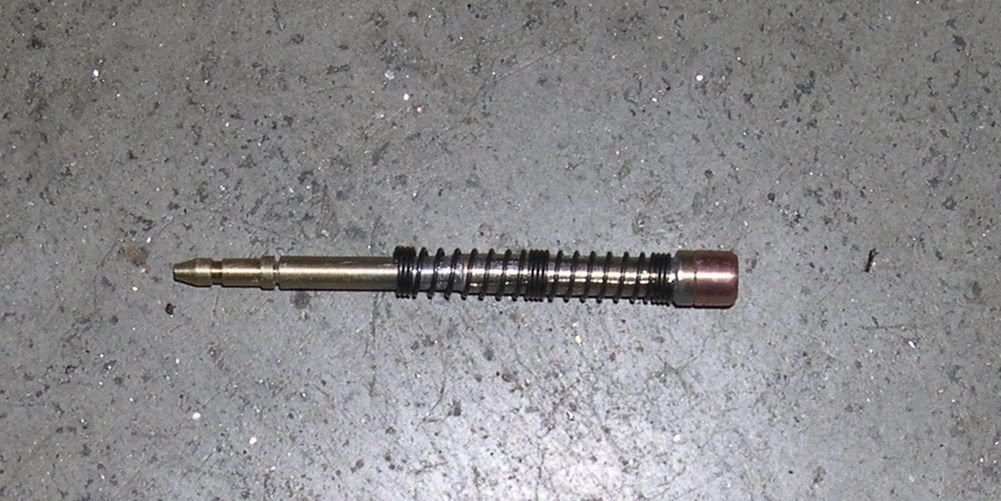
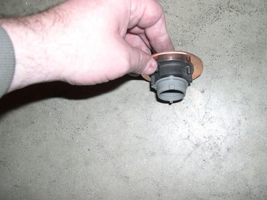
Here is a picture of the flasher unit (does both signals as well as hazards).
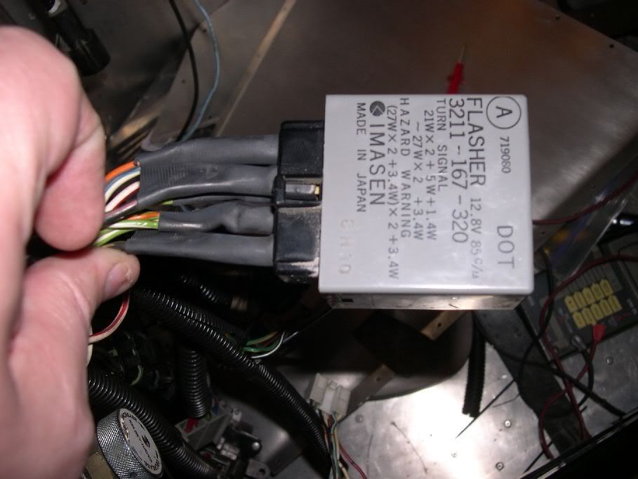
On the ’89 Probe this was located with several other components on the firewall just to the left of the steering shaft (mounted so that the connector end pointed into the firewall. From what I understand this particular unit may have only been available on the ‘89’s. I think Mazda 626’s also may have used them.
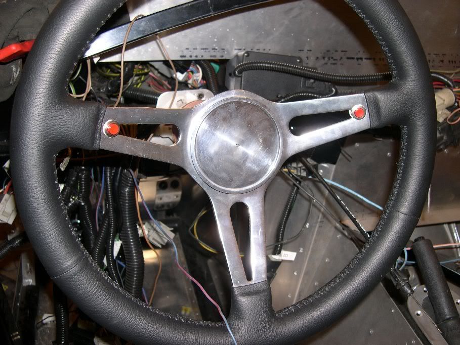
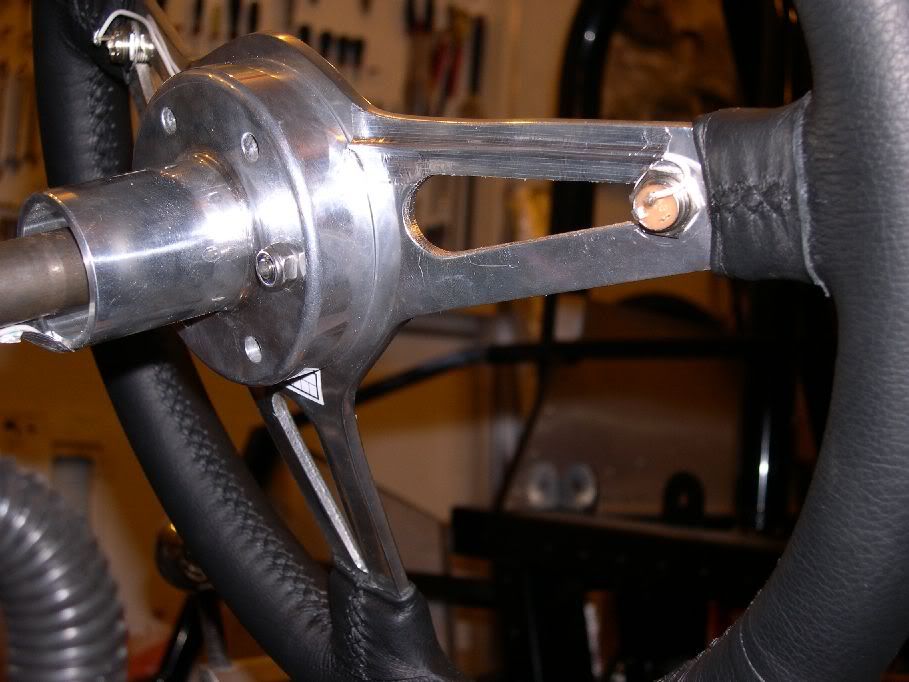
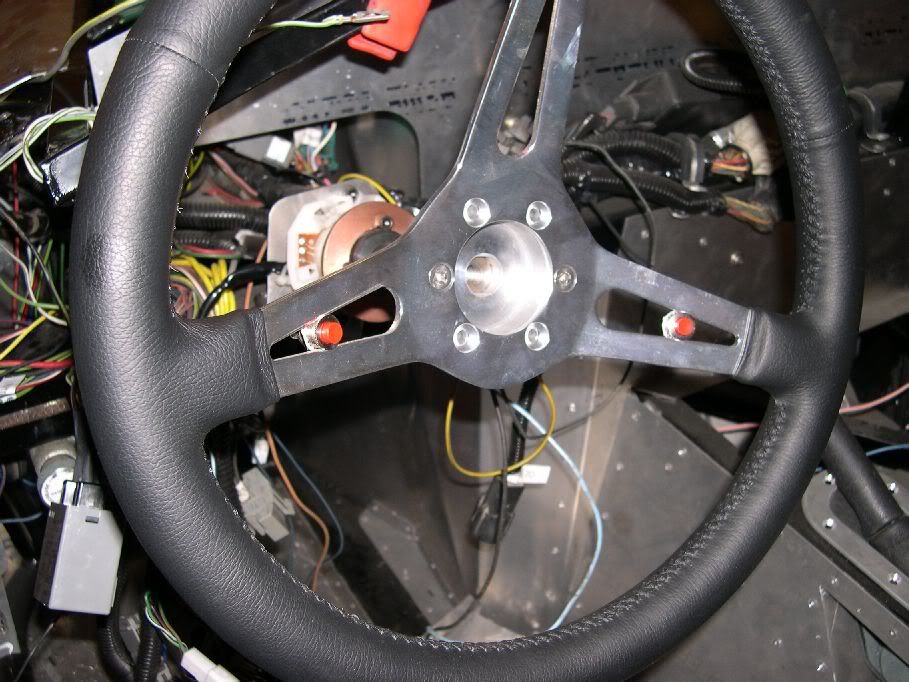
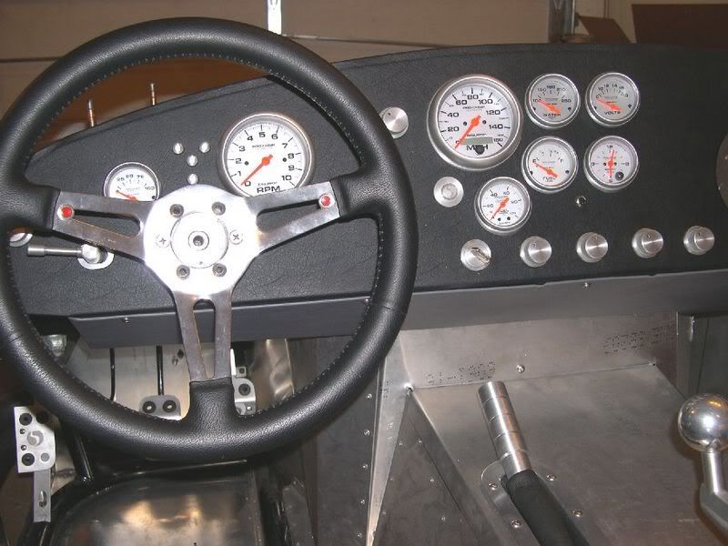
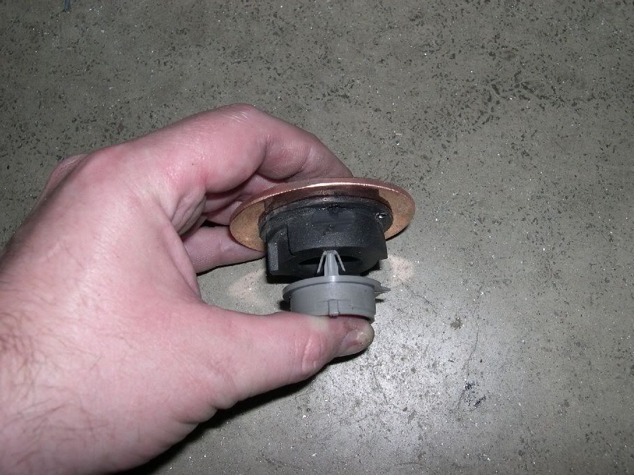
Here's a mock up of the horn buttons. In the final version they will be mounted futher out towards the rim.
I did a little more searching and found some more info on the flasher module. You can get it (just the module, not the switch) off the following cars:
'89 Ford Probe
'94-'96 Ford Escort
'94-'96 Mercury Tracer
It is $70 new so a scrap yard is the way to go. We picked up a couple of units for $20 each for the whole setup (removed ourselves).
-
Member
Just got back from the scrap yard and thought I would let you know that I confirmed that the flasher unit is the same on the '94-'96 Escorts. It is actually a better source since, on the Escort, the flasher is connected by a connector and harness which you can splice into your existing harness. On the Probe it plugged into some sort of block so, as you can see above, you have to use 1/4" female spade connectors to hook it up. I will be swapping out mine to put in the connector from the Escort.
-
Member
-
Member
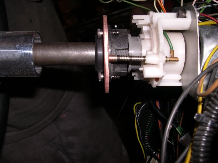
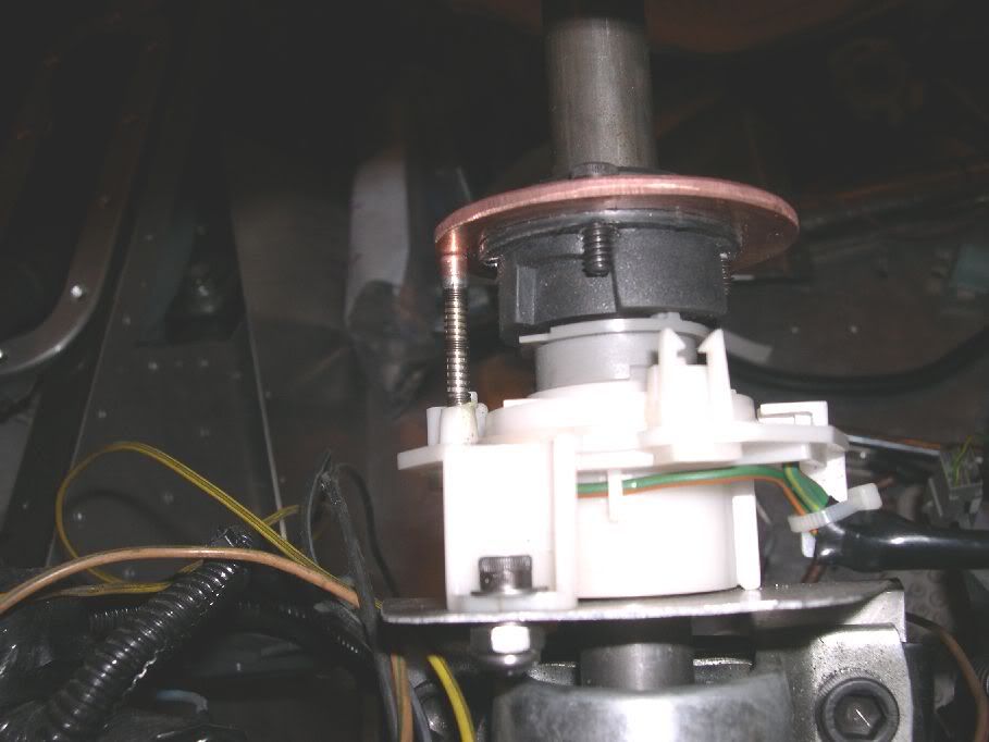
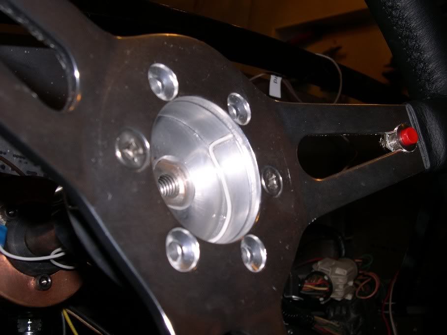
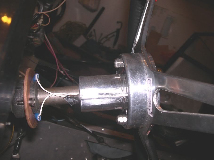
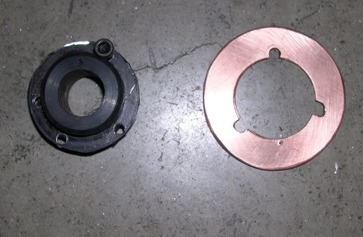
Where they connect to the copper ring.
-
Senior Member

Just had to bring that over didnt you  Kidding.
Show your parking Brake mod as well.
Oh, and dont forget the booster too.
I'm using the turn signal and the booster mods. Thanks for the work you've done on those and sharing.
Last edited by rich grsc; 10-06-2012 at 09:51 AM.
-
Member
Here you go. Looking at the back of the switch.
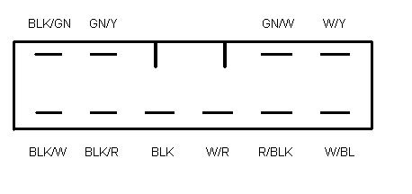
And here's the connector.
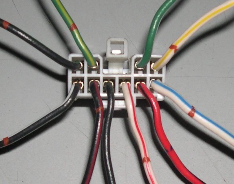
hazards are activated by grounding one of the wires on the flasher unit. A dash toggle or rocker switch is all that's required. Works like a charm.
As for the flash-to-pass, I tried to figure that on out and fried one of the switches. So no I don't know how it would hook up and I don't plan on trying again. I always run with my head lights on anyway for safety (even more so with this car) and a simple pull will toggle the high/low anyway. I assume that feature was for if you had your lights in the off position and pulled for flash to pass.
-
Member
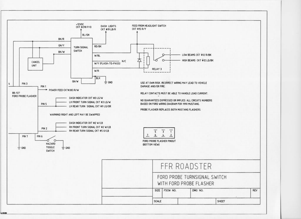
The main thing from the other post is the wiring diagram the original guy was kind enough to post. Wish I knew who it was to give credit.
-
Member
Final product with a custom billet handle.
Cheers, Rod
Tags for this Thread
 Posting Permissions
- You may not post new threads
- You may not post replies
- You may not post attachments
- You may not edit your posts
-
Forum Rules

Visit our community sponsor


 Reply With Quote