
Visit our community sponsor

Thanks:
0

Likes:
0
-
Senior Member

Wiring questions
Hi everyone,
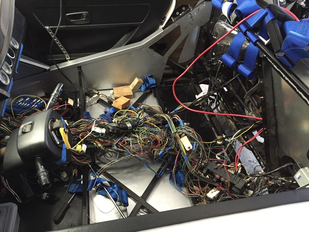
We have managed to get 13.5lbs off our OEM 2002 WRX wiring harness so far, and hoping for a bit more.
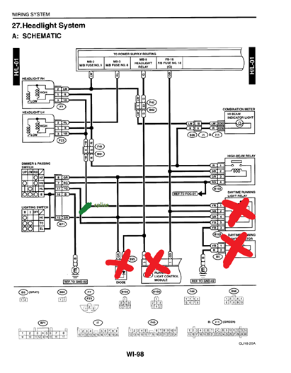
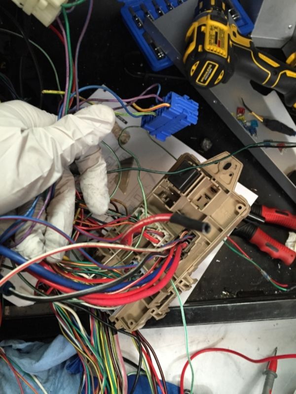
MikeB75 posted this photo on the forum a little while back regarding deleting the daytime running lights... just wanted to confirm that we can delete everything he did, and also that we are doing it right. The daytime running light relay (also known as the low beam relay, right?) is the black relay near the blue relay (high beam), correct - and it can be fully deleted along with associated wires? There's also a little diode off of it... delete it as well? Delete the silver box with "caution high temp" and the black DRL module, and then jumper the yellow/green to the yellow/red wire -right?
For the integraded unit, I found these two lists on the forum. Can anyone confirm if these are the same for a 2002 WRX, and which specific ones need to be jumpered?

Originally Posted by
mxl

Hi tmoretta the info that I can help you with is for a 2004 STI, but I'm working in a 2004 WRX wiring and the integrated unit is exacly the same... Blue Plug
1: (LR) K/L-02 (Keyless Entry Module?)
2: (WB) Battery Power Supply
3: Key Lock Solenoid
4: (B) Ground
5: (L) Room Light
6: (Or) Lock All Doors (Actuators)
7: (RG) Unlock Passenger Doors (Actuators)
8: (R) Unlock Driver Door (Actuator)
9: Shift Lock Solenoid
10: (L) FB-15 Rear Defogger Relay
11: (BL) Seatbelt Warning Light
12
13: (B) Ground
14
15
16
Gray Plug
1: (R) Rear Defogger Switch
2: (YB) Key Illumination Light
3: (BrR) Seatbelt Switch
4
5: Inhibitor Switch ("P" range)
6: "P" (Park) Range Switch
7: (Y) + All Passenger Door Switches
8: (LOr) + Drivers Door Switches
9: Stop (Brake?) Light Switch
10: Ignition Switch ACC
11: (YR) Lock/Unlock? Doors (Switch)
12: (RW) Lock/Unlock? Doors (Switch)
13: (OrW) Keyless Entry Control Module Pin 1
14: (OrB) Keyless Entry Control Module Pin 2
15: (V) Illumination
16: (GrR) Lighting Switch (V3)
17: (LW) Trunk Light
18: (L) Lighting Switch (V2)
19: (GR) Ignition Switch IG
20: (WR) Key Warning Switch
Originally Posted by
billjr212
This was my initial summary for the plugs in a 2004 WRX:
B280 (Blue) - Integrated Module
1 LR Power/Keyless entry Delete
2 WB Power, Fuse 3 FB-33 ?
3
4 B Ground
5 L Room Light Delete
6 Or Door locks Delete
7 RG Door locks Delete
8 R Driver door lock Delete
9
10 L Rear Defog, ECM FB-15 Delete?
11 BL Seat Belt Light Delete
12
13 B Ground
14 OrW Lighting - various Keep portion?
15
16
B281 (Gray) - Integrated Module
1 R Rear Defog switch Delete
2 YB Key illum light Keep?
3 BrR Seat Belt Switch Delete
4 BrY Auto trans only? X
5
6
7 Y Keyless entry module/FR door switch Delete
8 L Or Driver door switch and light on cluster Delete
9
10
11 YR Driver door lock button, keyless entry Delete
12 RW Driver door lock button, keyless entry Delete
13 OrW Keyless entry module Delete
14 OrB Keyless entry module Delete
15 V Various lighting - power Keep portion?
16 GrR Lighting switch B71 Keep
17 LW Trunk light Delete
18 L Lighting switch B71 Keep
19 GR Power FB-20, Fuse 11 Keep
20 WR Key Warning Switch/Keyless entry Delete
Originally Posted by
Jaime
Backlighting goes through the integrated unit. A simple workaround is to wire up an on/off switch that grounds the Orange/White wire to turn the lights on full brightness. More complicated is to create a simple pulse width dimmer that's controlled by the dimmer knob. It should only be about ten bucks worth of electronics parts.
So #14 orange white wire - wire directly into headlight power? What about #9 for brake lights?
What do the grey plug other lighting switches, #15,16,18 power? What about #10 and 19 relating to ignition?
Any others need to be kept/jumped?
Originally Posted by
STiPWRD
I'm dieting my 2002 harness now and wanted to make sure I understood the consensus on the Integrated module. In order to delete it completely:
On B280: Ground pin 4 (Black)
On B281: Keep pin 16 (GrR) Lighting switch to B71
On B281: Keep pin 18 (L) Lighting switch to B71
On B281: Keep pin 19 (GR) Power to FB-20, Fuse
Delete all other wires
What do I do with the wires I keep? I'm deleting all the interior lighting but want to make sure I can illuminate the combination meter (dimmer not necessary). Would I need an on/off switch to ground on the two wires that run to B71? Can they be spliced to use the same on/off switch?
Jaime also, mentioned wiring an on/off switch to GND on the Orange/White (on B281 pin 13) wire but this wire runs to the keyless entry module, which I already deleted. Do I need to worry about this OrW wire?
Thanks for the help!
Also, is anyone deleting the DRL system?
STIPWRD posted the above but never got a response. I would like to know too - Anyone have an answer for us?
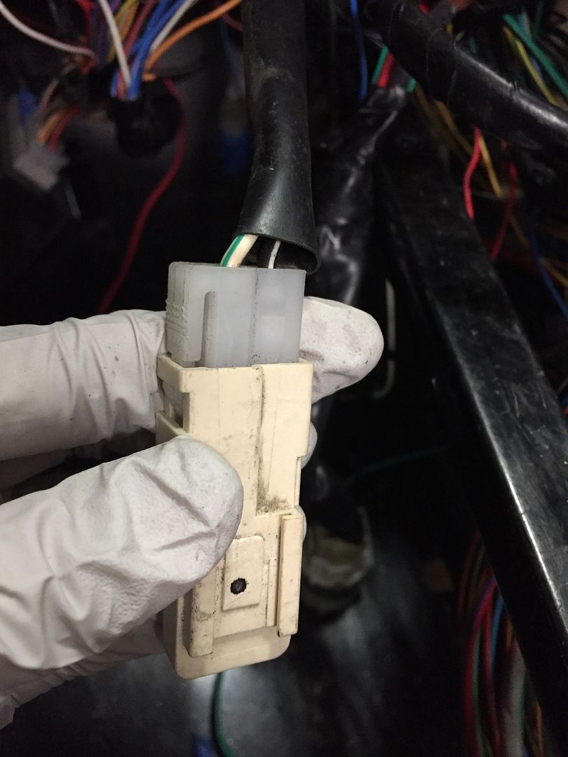
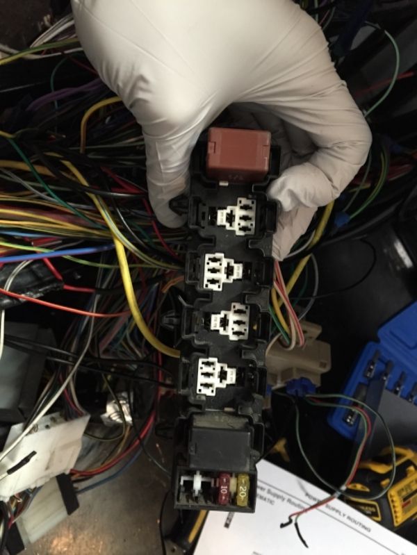
To confirm - this is the power window circuit breaker and can be deleted fully?
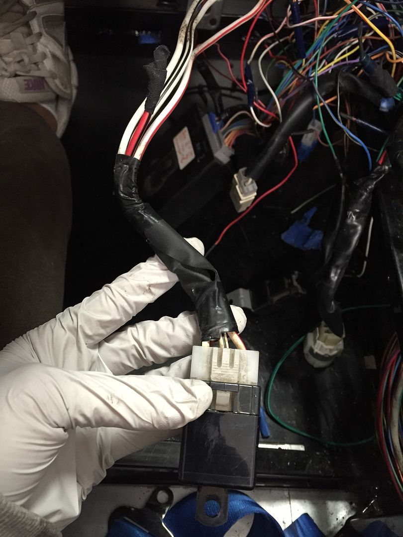
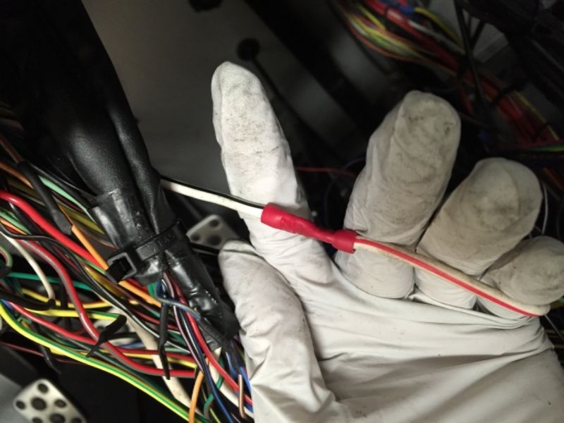
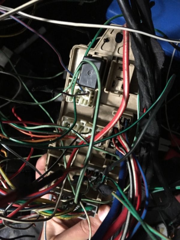
Any ideas what this one is? We deleted a wire from an unused connector and traced it back to this one, so guess it isn't necessary...?
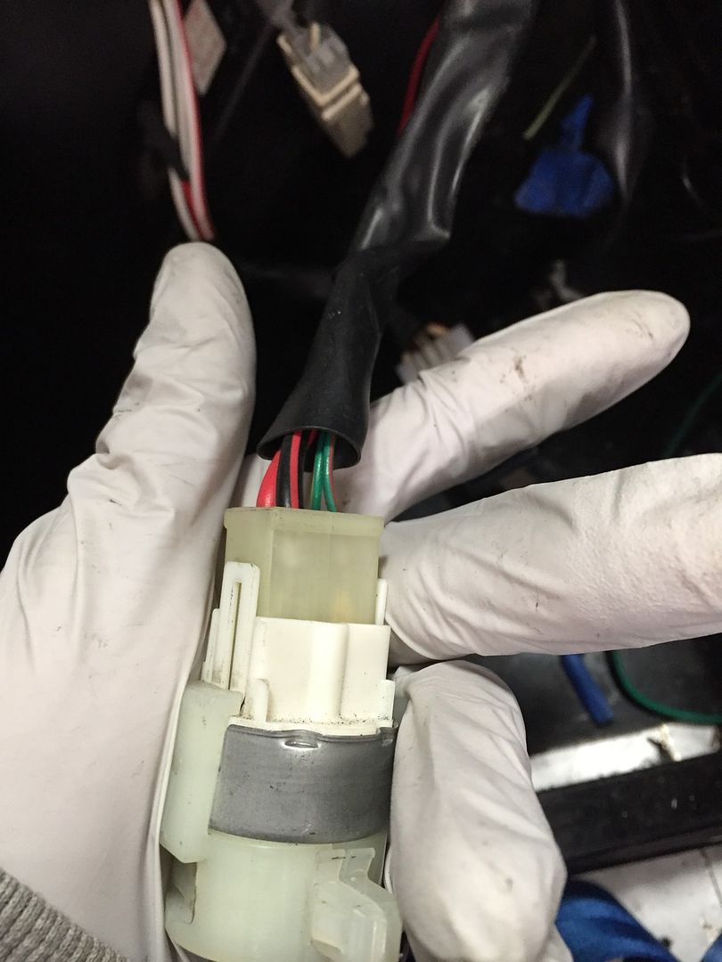
So this looks like the HVAC relay to me, but there is one wire that doesn't match up with the wiring diagram. It looks green/yellow, and the diagram calls for green/orange. Can anyone confirm if this can be deleted?
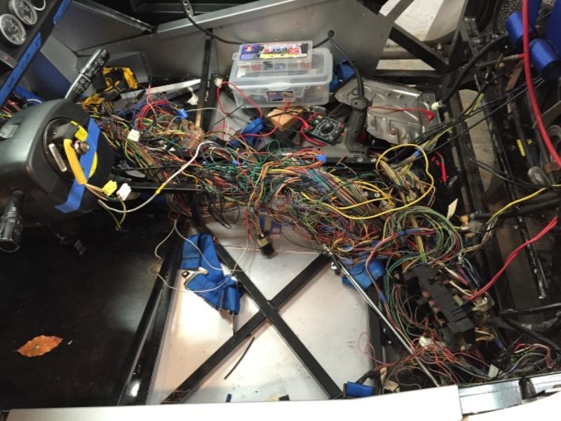
This is what the car looks like right now, with a theoretically 49-13.5lb = 35.5lb harness. Only 7.5lbs more and it'll look just like an Iwire, right??? LOL
Tamra
Building 818SR #297 picked up 10/25/14 with Andrew (xxguitarist)
First start 12/21/14,
First "drive" 1/17/15
First Dyno at EFI Logics 3/7/15- 310whp at 15psi for break in, full spool by ~3500rpm!
First autocross 3/29/15
1st Registered 818 in Connecticut 7/24/2015. 9 months - 1 day from kit pickup!
-
Moonlight Performance


Originally Posted by
Tamra
Any ideas what this one is? We deleted a wire from an unused connector and traced it back to this one, so guess it isn't necessary...?
That looks like the starter-cut relay. The red and black wire you cut goes to the keyless entry unit. The relay is not like the other relays in that it is normally closed instead of normally open. So you should be fine. I removed that relay completely. To do that, just connect the white and black wire to the white and red wire. There are two white and black wires but they splice together further up the harness.
You are correct about the power window thing - ditch it.
-
Senior Member
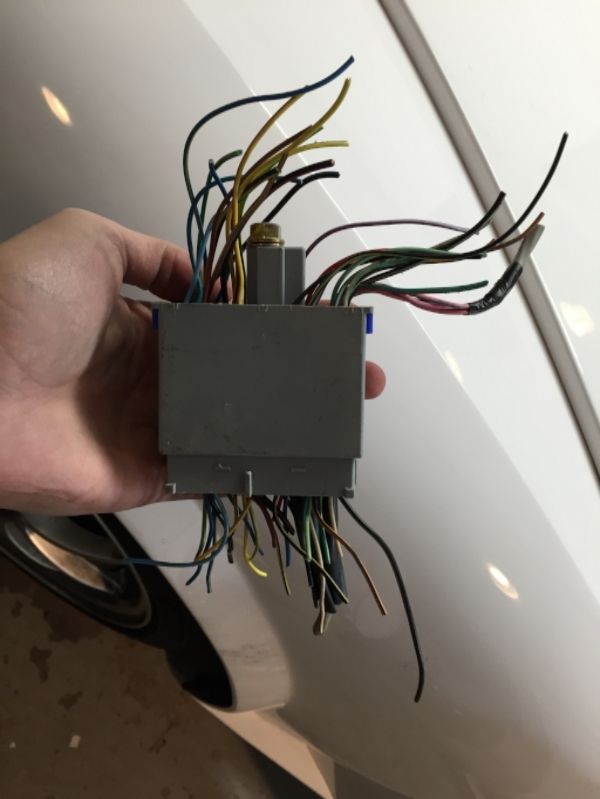
Thanks so much, Hindsight! Any idea on the white relay or the integrated unit?
Tamra
Building 818SR #297 picked up 10/25/14 with Andrew (xxguitarist)
First start 12/21/14,
First "drive" 1/17/15
First Dyno at EFI Logics 3/7/15- 310whp at 15psi for break in, full spool by ~3500rpm!
First autocross 3/29/15
1st Registered 818 in Connecticut 7/24/2015. 9 months - 1 day from kit pickup!
-
Moonlight Performance
The white relay looks like the blower motor relay, but yeah the colors aren't right. When that happened to me, I traced the wires back to where they go to see. Easiest way is to trace it back to the fusebox and see what it plugs into there. That should give you a good indicator. If the red and black wire from the relay traces back to the back of the tan fuse box and the wire is SUPER thick all the way to the fuse box (you'll notice it's the biggest wire the plugs into any connector on back of the fusebox), that is definitely the blower motor relay which can be removed.
I can't help you on the body integrated sorry. I removed just a couple wires from it that I thought I could and a TON of stuff stopped working (instrument cluster lighting for example). I know if you are good and know what to apply power or ground to, you can remove it and keep all the features but I'm not that good. You start removing that, and diodes, and messing with headlight relays without knowing what you are doing and it's a recipe for a real headache. My solution was to just leave the body integrated in place. The dome lights are controlled through the body integrated unit as well. I did delete the keyless entry module and removed all wires to the body integrated from it, and from other things I knew I didn't need. I left the DRL relay in place (yes it's the black one next to the blue relay) and am going to delete the DRL feature by simply leaving the black resistor box unplugged and out of the car (the one that says "Caution hot" on it). I don't think you save that much wire/weight by removing the body integrated and so many things are tangled into it.
Last edited by Hindsight; 11-28-2015 at 10:08 PM.
-
Senior Member

I had a 2002 WRX donor and I did delete the daytime running lights. The relay, resistor etc. It did require a little rewiring to get the low beams working. I also deleted the integrated unit. The only thing lost was the dimmer for the cluster. I just hardwired the cluster lights full bright. I have go-karted a few times and everything still works.
-
Senior Member

It wont hurt to unplug it and see what stops working.
IM.PNG
-
Senior Member

I deleted the integrated unit also with no issues. You'll actually eliminate a significant amount of wiring by removing it. As Quincy said, the cluster illumination switch is the only thing you have to go back and fix. I have an sti cluster (and I think you do as well?) so it is always illuminated, aka no need to re-wire the switch.
I kept the DRL system.
-
Senior Member

The integrated unit seems to do the dimming function (as others state) among other things; but after removing it and re-establishing the ground connection post instrument cluster I have found that the illumination works correctly: the dash is only lit when the headlights are on.
Likewise, I confirm the headlights work after removing the DRL hardware  . I will see if I can get my father-in-law to chime in on this thread since he did all the wiring harness dieting.
818SC chassis #206 EJ207 2.0L VF37 twin scroll || Cusco type RS 1.5 LSD || Wilwood pedal box (firewall attach) || Wilwood superlite front calipers
BUILD Phase 1: 6/6/2014 car delivered || 5/24/2015 first start || 6/7/2015 go karted || 4/20/2016 hard-top-topped || 10/25/2016 registered || 11/18/2016 inspected & complete
BUILD Phase 2: 3/8/2017 EJ207v8 || 5/29/2017 re-first re-start || 7/17/2017 re-assembled with race car bits
-
Senior Member
Thanks everyone for your feedback. We deleted the integrated unit entirely. We tried what Touchstone said and unplugged the two connectors, and found that everything still worked as intended. Since we have the STI dash, even the lights still work. Unfortunately, most of the wires are going right to the dash, so it didn't delete much out of the center console area, which is where we are hoping to thin out.
Also - Hindsight - thanks for the tip on the starter wires. We crimped them together and cut out that black relay entirey, and the car still turns over.
We've also deleted much of the side relay box. We may cut this down a bit.
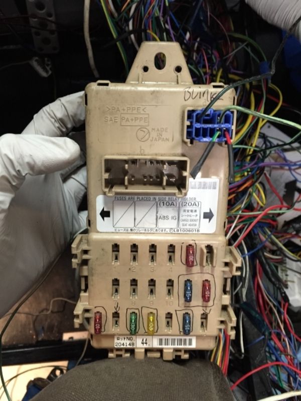
We also worked on cutting down the tan fuse box. Many of the fuses relate to things we don't have anymore. We were able to get two connectors and one relay removed. The others all affected lights of some sort. We tried using a multimeter between the fuse side and the wiring side to see which pins were connected, but that was time consuming and confusing. We were ohming out which wire was fused by which fuse, and it it seemed like the unfused side switched from the top to the bottom, which meant we had to be careful about which side we were looking at. We deleted the ones we were 100% sure on, and then tested by unplugging connectors on the remaining ones, resulting in the following:
So this is what the car still looks like after another 2lbs of wiring removal today. Not much visual progress, despite only being 5lbs away from the Iwire weight.
Does anyone have diagrams of the main fuse box or the ECU wiring for which wires we can delete? We are really wanting to clear out the center console a bit. Any ideas?
Tamra
Building 818SR #297 picked up 10/25/14 with Andrew (xxguitarist)
First start 12/21/14,
First "drive" 1/17/15
First Dyno at EFI Logics 3/7/15- 310whp at 15psi for break in, full spool by ~3500rpm!
First autocross 3/29/15
1st Registered 818 in Connecticut 7/24/2015. 9 months - 1 day from kit pickup!
-
Senior Member
One thing you could do is eliminate the SMJ connector. Most (if not all) of the wiring coming from the engine (injectors, coils, sensors, etc...) runs through this connector and then to the ECU. If you mounted your ECU on the rear firewall, as I did, all of that wiring from the engine runs through the center console, does a U-turn and then goes back into the ECU. You can cut down much of this unnecessary wiring. It should really clean things up.
IMAG1423.jpgIMAG1424.jpg
-
Senior Member

Yep, our SMJ is currently near the passenger's feet.
It was seeming like we were running short on wires to fully remove, yet we still had an awfully big pile of them left.
-Andrew
Building 818S/R #297 with Tamra
08 Mazdaspeed3 | '12 F800R | '97 Miata
-
Senior Member
Thanks STIPWRD! I'll dig into that tonight!
Tamra
Building 818SR #297 picked up 10/25/14 with Andrew (xxguitarist)
First start 12/21/14,
First "drive" 1/17/15
First Dyno at EFI Logics 3/7/15- 310whp at 15psi for break in, full spool by ~3500rpm!
First autocross 3/29/15
1st Registered 818 in Connecticut 7/24/2015. 9 months - 1 day from kit pickup!
-
Senior Member

I deleted a lot of relays and the fuel pump controller and put switches in instead (cooling fans, fuel pumps, etc). Not only can you do more, like shut the car off and keep the fans running, or pump gas out of the tank, but you can also save a little weight. Especially with no fuel pump controller. Silly PWM circuits. Just run 12V to her all day
-
Moonlight Performance
Tamra, on the relays..... there are two relay blocks: One that is mounted to the fusebox top and another that is remote. Based on all the relays you remove, you should have few enough left that you can consolidate them all into one of the blocks. De-pinning the female spade terminals to move them from one block to the other is a bit of pain. After removing the relay, go in from the front side (relay-side) of the block, not the back side (wire side). Use a small straight pick tool and pry up the lock while you pull out on the wire. Look at an empty slot to see what the locking tab looks like and which side it sits on.
If you cut any wires to the ECU and you want to de-pin them, it's a two part process. The connector has a locking piece that needs to be pried up from the outside on top. Then you have to go in with a thin blade pin removal tool (or a tiny jeweler's screwdriver) to release the inner locking tab. There are so many wires to the ECU connectors that any you can remove is a benefit.
-
Senior Member
I deleted the SMJ and shortened all of the wires back to the firewall tonight. It was 30 wires, so a total of 60 (since they looped forward and back) out of the center console.
Actually starting to get a noticeable before and after difference:
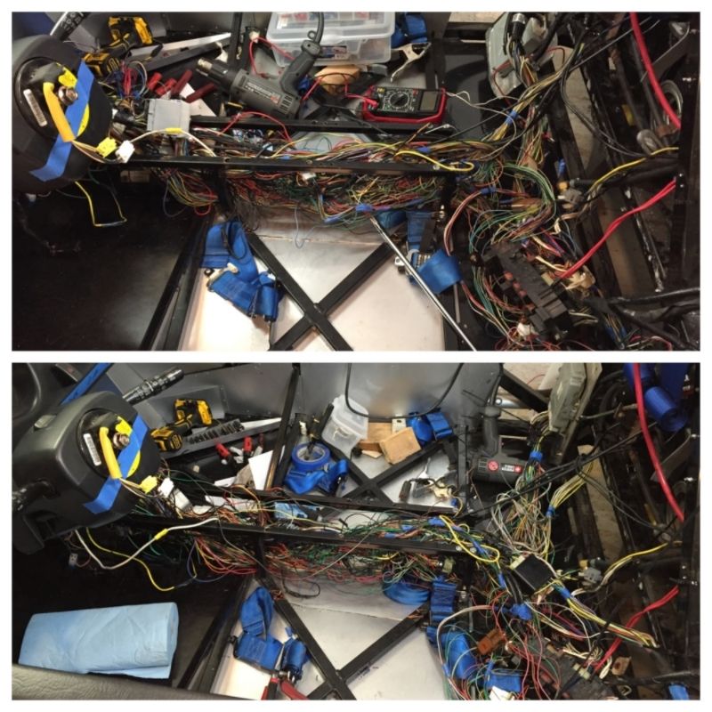
The wires aren't super tidy yet so I imagine we can get them cleaned up a bit more. Still lots of wire options to shorten as well...
Weight after tonight is 6 3/4lbs additional removed (now for a total of 16 3/4lbs off the original harness).
Hindsight- I'll let Andrew interpret your post. That's over my head! I'm happy I can cut and solder and heat shrink wires right now (I go one at a time to make sure I don't cross any - took me 3 hours to do the 30 wires tonight!). Andrew said my soldering technique is pretty good though
Tamra
Building 818SR #297 picked up 10/25/14 with Andrew (xxguitarist)
First start 12/21/14,
First "drive" 1/17/15
First Dyno at EFI Logics 3/7/15- 310whp at 15psi for break in, full spool by ~3500rpm!
First autocross 3/29/15
1st Registered 818 in Connecticut 7/24/2015. 9 months - 1 day from kit pickup!
-
Senior Member
Nice job! That looks way better! Easier to troubleshoot and lighter. Colin Chapman would be proud.
I'm with Hindsight on removing unnecessary relays. Except my strategy was remove them all and put back the ones I need.
"It's much better to ask what the driver needs rather than what he can do without"
-
Senior Member
Originally Posted by
Tamra
I deleted the SMJ and shortened all of the wires back to the firewall tonight. It was 30 wires, so a total of 60 (since they looped forward and back) out of the center console.
Actually starting to get a noticeable before and after difference
Awesome, glad it worked out. Would it be possible to relocate your relay block and fuse boxes under the dash? That would really clean up the console.
-
Senior Member
Making some progress on the wiring harness.
Before:
After: 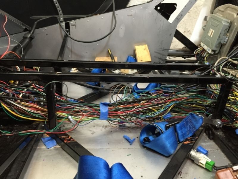
This is an additional 10 lbs of wiring removed, now for a total of 20lbs removed. Total harness started at 48lbs, so now should be 28lbs, about the same as an Iwire.
Note: we deleted the daytime running light stuff like the first photo o f this thread. We found out that that we could not delete the diode that he crossed off, so had to wire it back in. I'll post an updated version of the wiring manual sometime tomorrow.
The biggest gains have come from shortening wires that were looping back and forth through the console, not from actually "deleting" anything.
Also, in one of the previous photos I posted showing a connector we thought we could delete. This was an error, as it has wiring controlling the high beams. It's the white one in the upper left. The green/black wire runs to the high beam relay.
Tamra
Building 818SR #297 picked up 10/25/14 with Andrew (xxguitarist)
First start 12/21/14,
First "drive" 1/17/15
First Dyno at EFI Logics 3/7/15- 310whp at 15psi for break in, full spool by ~3500rpm!
First autocross 3/29/15
1st Registered 818 in Connecticut 7/24/2015. 9 months - 1 day from kit pickup!
-
Senior Member

Looking good.
I'd like to throw this out there;
Its not too late to delete the Main Fuse Box (M/B) and the Fuse & Relay Box (F/B) with a "Bussmann 15401-2-0-1-0A". iWire uses 2, and sometimes 3, of the smaller versions.
Bussmann Box.jpg
You would save a bunch of weight, space, and simplify things. As you can now see, there are very little fuses/relays still in use from the factory fuse boxes. Much of the M/B feeds the F/B. The Bussmann box mounts so much nicer, and is waterproof. You can keep all the names and wire colors, to keep the new fuse box as 'factory' as possible for future trouble shooting. 80% of the power wires get shorter, just extend the rest.
There are a few down sides to doing this. First is that it will cost about $200 in parts and tools, and second it took me about 4 hours to sort through and install.
-
Moonlight Performance
I really wanted to go with one of those but it would have taken me (personally) more like 4 days to convert all the wiring required. I may be running more relays and modules than some others though.
-
Senior Member
-
Well I am going to bring this back from the dead because I am having issues with my headlights flickering. They will be working perfectly for 30 minutes and then all of a sudden they go out. I honestly thought it was a loose ground that was causing it so I have taken all the wiring out again to diagnose the problem. While I was doing so I thought that I should potentially remove the DRL just incase a relay or such is the problem. Just to confirm with what Tamara has done I can delete everything related to the DRL box and also the black relay that is located next to the blue one. Also I didn't realize that high temp resistor was related to the headlights, so I can remove that as well? I don't ever remember seeing a diode which maybe the problem right there. Does anyone have a picture of it?
Also another issue I was having was power to the clearance lights. I ended up tapping into a power source else where to get them online but if anyone knows how they should have been originally wired that would be much appreciated. I have completed removed the integrated unit of that makes any difference.
Thanks in advance
-
Also, is there two of what looks like that blower motor relay? I have a 2003 harness but it should be the same and for some reason I think I remember two of those...
-
Senior Member
Originally Posted by
iblackwe
Well I am going to bring this back from the dead because I am having issues with my headlights flickering. They will be working perfectly for 30 minutes and then all of a sudden they go out. I honestly thought it was a loose ground that was causing it so I have taken all the wiring out again to diagnose the problem. While I was doing so I thought that I should potentially remove the DRL just incase a relay or such is the problem. Just to confirm with what Tamara has done I can delete everything related to the DRL box and also the black relay that is located next to the blue one. Also I didn't realize that high temp resistor was related to the headlights, so I can remove that as well? I don't ever remember seeing a diode which maybe the problem right there. Does anyone have a picture of it?
Also another issue I was having was power to the clearance lights. I ended up tapping into a power source else where to get them online but if anyone knows how they should have been originally wired that would be much appreciated. I have completed removed the integrated unit of that makes any difference.
Thanks in advance
Bad relay could be the cause.
You can delete the DRL and large power resistor.
-
Awesome I needed that confirmation. Any ideas on the clearance light issue?
-
Senior Member
Originally Posted by
iblackwe
Awesome I needed that confirmation. Any ideas on the clearance light issue?
Clearance lights are connected to fuse #5. Check if its bad. Here is the wiring diagram for the 02-03: http://ken-gilbert.com/wrx/mans/7%20-%20WIRING.PDF other than that I would need more information.
-
How crucial is that diode that wires in with the day time running lights? I realized I had removed it without knowing what it had exactly done. Would that be what is causing my headlights to randomly cut out?
Also, to replace it I have found many on eBay and I am assuming it would only have to be a 12v say 1 amp diode?
Thanks!
-
Senior Member
If you got rid of the DRL Control Module then you dont need the diode but you do need to keep an electrical connection. You can do one of the following A) delete the diode and short the wires or B) Keep the diode (needs to be roughly >500mA). I'm sort of surprised your headlights work at all.
Last edited by TouchStone; 06-09-2016 at 11:31 PM.
-

Yes, I love Technology

About - what does the diode do? - and for that matter how the Daytime Running Light circuit works.
I'm contemplating a fairly detailed tutorial on how to trace through the manual - wiring, using 2002 as an example. I guess if people started asking I'd do it.
If you find tracing these circuits difficult, then just take a nibble at a time, and carefully follow the wires. Here is a tickle to get you started.
Before even going there, MikeB75's drawing above in thread #1 is great solution - it gets rid of relays, the running light module, the resistor and diode. You must add the connection in green if you didn't catch that. It provides the "low" or "ground" connection to the low beam filaments that would have come from those removed circuits.
I'm going to walk through what the factory version does. Just in case someone wants to keep alll that intact, and as an exercise in tracing this circuit to understand it.
"Daytime Running Light Control Module" = "DRL control"
"Daytime Running Light Relay" = "DRL relay"
"Daytime Running Light Resistor" = "DRL resistor"
The quick answer is - the diode allows the two headlight switches and the "DRL control" to share a common control line to energize the headlight relays, when desired. But it prevents a "backward" connection from the "DRL control" from incorrectly energizing the "DRL relay". If that "backward" connection was not blocked by a diode, the "DRL relay" would get energized whenever the daytime running mode was "on" and so the dimming resistor would never be used - the low beam would be at full intensity even with DRL mode on.
Refer to MikeB75's drawing in thread #1, and the factory wiring document linked in TouchStone's thread #26 above. The "daytime running light" is accomplished by placing a resistor in series with the low beam lamps' filaments, and at the same time, turning on the headlight relays, which supply the battery + to the headlights. Now the low beams are on, but at a lower intensity because of the resistor. The "DRL relay" must be de-energized or "off" in order to be in the "DRL" mode (this is how relays are usually drawn - showing the "off" state connections).
So for "daytime running lights on mode", first have the dimmer and light switches turned off. With these switches off, grounds are not supplied to the headlights, and the headlight relays are not turned on. At least not by these switches.
The "DRL relay" coil is connected on one side to a 12V fuse circuit, via the relay's connector B102-2. The other coil terminal (B102-4) connects to the diode and to both light switches (dimmer and lighting) (as well as the high beam relay - but we'll skip that today). With the "Lighting Switch" and "Dimmer & Passing Switch" both off, the "DRL relay" is also off, because the switches in their off positions do not supply any connections between the relay coil and ground. The relay then connects the resistor to the low beam lamp filaments. The other side of the resistor is connected to ground...
All that is needed now to energize dimmed "daytime", low beams is to turn on the headlight relays. The "DRL control", does this by sending a low (it internally connects a "ground") out on connector B96-5-G. This goes up to the headlight relays, at MB-8 (top of the drawing). The other side of the headlight relay coils are powered by battery+ 12V supplied by the ignition switch "on". The headlight relays turn on, and they each supply battery+ to their respective left and right headlight common filament connections via the fuses #8, #9. The low beam circuit is completed, but through the resistor = dim low beams are now on.
The reason for the diode? Stick with me - this takes a moment to work through. One common "command line" can be used to turn on the headlight relays which is that wire on the H/L-01 page top center we just traced - going to "Headlight Relay MB-8". Place a low here, the headlight relays turn on to provide the +12V supply to the lamps. We need any of the three devices, "Dimmer & Passing Switch" or "Lighting Switch" or "DRL control" to be able to turn on the headlight relays. BUT if either of the control switches turn on those relays, we want that dimming resistor removed, so that the lamps are at normal - full - intensity.
The "DRL relay" is turned on when a low (ground) is supplied to its connector "B102-4". Tracing this to wherever it is connected we find: the "Diode" at (B95-2), the "Lighting Switch" at (B71-13) and the "Dimmer & Passing Switch" at (B71-8) (and that high beam relay... skip).
To trace this carefully:
"Lighting Switch" - position II will connect GND from B71-16 to switch "EL" to switch "HC" to B71-13 to the "DRL relay", the relay turns on. The relay now connects the low beam lamp filaments at relay connector B102-1 to B102-5. Tracing this to "Dimmer & Passing Switch" connector B71-17 to the switch "HL". If this switch is set to Low beam on, then it connects "HL" to "E" which is our "ground" at GND-02. So with the "DRL relay" energized or "on", the resistor is replaced with a direct ground. The low beam is full on.
"Dimmer & Passing Switch" - in passing position will connect GND from B71-16 to switch "E" to switch "HF" (high flash) to B71-8 to "DRL relay" connector B102-4 which, like the "Lighting Switch" will energize the relay to replace the resistor with a direct ground. The "Dimmer & Passing Switch" in this position, disconnects "E" from "HL", and tracing that out to the "DRL relay" we see that the low beam will not get a ground nor the resistor, and will remain off.
Last edited by aquillen; 06-10-2016 at 10:59 AM.
-
That was so helpful thank you very much! That post needs a sticky because I believe it would solve any questions/problems others are having.
I have followed the previous diagram and have taken out the diode which now makes sense because the DRL module will not be Switching on as it is removed.
If by any chance you are open to suggestions on what/how to wire the clearance lights I would be very interested. I have heard many get power from the purple power wire (accessory power) in order to wire them in. For some reason I am not able to power mine and have also had to splice into an existing power string. The red/yellow wire that was supposed to power the lights does not receive power and I have checked all fuses. I am wondering if it has anything to do with the parking switch circuit as this might be causing the problem.
Thanks again that was very helpful!
-
Yes, I love Technology
I think I've seen several comments about the clearance light wiring. I'm nearly finished with a pair of drawings on this. Based on 2002 Impreza so you can reference it. (I like that set, and my 818 3.0 will use the 2002 Legacy/Outback wiring as base info which is rather close in design to Impreza). The first drawing is a complete end to end trace of every circuit I could find on the clearance lights and related lamps groups, using factory designations and direct references to the factory wiring pages - ie. a way to 1:1 trace it out. Everything on one big sheet of "paper". The second drawing (doing it now) will be the same thing, but distilled into a cleaner, easier to follow drawing reflecting the same stuff however. From that guys & gals can hopefully peek and poke around to decide what to keep, how to hook up parts of these circuits. Should be posted in next day or so (work permitting)...
 Posting Permissions
- You may not post new threads
- You may not post replies
- You may not post attachments
- You may not edit your posts
-
Forum Rules

Visit our community sponsor


 Reply With Quote


