
Visit our community sponsor

Thanks:
29

Likes:
38
-
Senior Member

Wiring Update
Progress continues with the wiring. I have everything in place now. Just need to make all the necessary connections and (hopefully) wrap it up. In a previous update I showed the power wiring from the front mounted battery to the disconnect along with the Coyote power distribution box wiring. Now for the rest.
First was the Ron Francis harness. I made a number of mods to the harness as supplied to make it fit a little better plus integrate with the 2015 Coyote controls pack harness. I removed the 33 hot rod specific leg. After checking the required lengths, I shortened the headlight and ignition switch legs. This makes a big difference in how the harness fits. Each was about one foot too long for where I located the respective switches. I removed the blue solenoid start and clutch interlock wires since they’re not needed for the Coyote. The only blue wire remaining is direct from the ignition switch to the start sense wire in the Coyote harness. I removed the cooling fan power and sensor wires from the front harness. This is provided through the Coyote harness plus eliminates a connector from the already crowded front harness through the DS footbox. I’m going to use the cooling fan circuit in the RF harness to power the aux outlets under the dash. I eliminated the connector on the gauge sending unit leg. Since only three of the wires are required (tach, oil pressure, water temp) I connected them directly and added them to the alternator leg since they go to the same place on the engine. Finally I broke into the fuel pump circuit in the RF fuse box and added the connection to the Coyote harness. The power and control for the fuel pump comes from the Coyote PDB and PCM, but it uses the existing RF wiring harness to get the +12V back to the in-tank fuel pump. It also uses the existing RF relay and inertia switch.
The Coyote harness also needed a little massaging to install the behind the dash wiring a little better. Nearly all of the connections were on the DS footbox end, which is already really congested. So I stripped back all the wrap and insulation, moved things around some, and then re-wrapped. In the process, adjusted the lengths of the various connections (clutch switches, DBW, ODB, etc.) to more closely match the installation. On the other side of the firewall, I previously mentioned moving the blue starter wire from the PCM location to the PDB location so it could route to the starter along with the battery cable. I also broke out the cooling fan wire and then routed it through a new harness I made for the PS front which has wires for the Tangent driving lights that will be in the front oil cooler, same as my previous builds. In the process, added a wire to the cooling fan wire back to the dash so I can have an indicator light when the fan is running.
With that all done, installed the main RF harness into the chassis along with the fuse panel. I did the power wiring much like my last build. I used a Blue Seas Systems bus bar for the main power. I have an 8 gauge wire from the switched side of the master disconnect to the bus bar. Then the three main power wires from the RF harness are attached. These are the same three wires that are normally attached to a firewall solenoid instead making just a 6-8 inch trip to the bus bar. Then I added a Blue Seas Systems 150 amp fuse to the alternator circuit. Typically DD’s have a fusable link in the alternator circuit. In stock form the RF harness has no protection from an alternator failure. Not typically a problem, but still something I prefer to add.
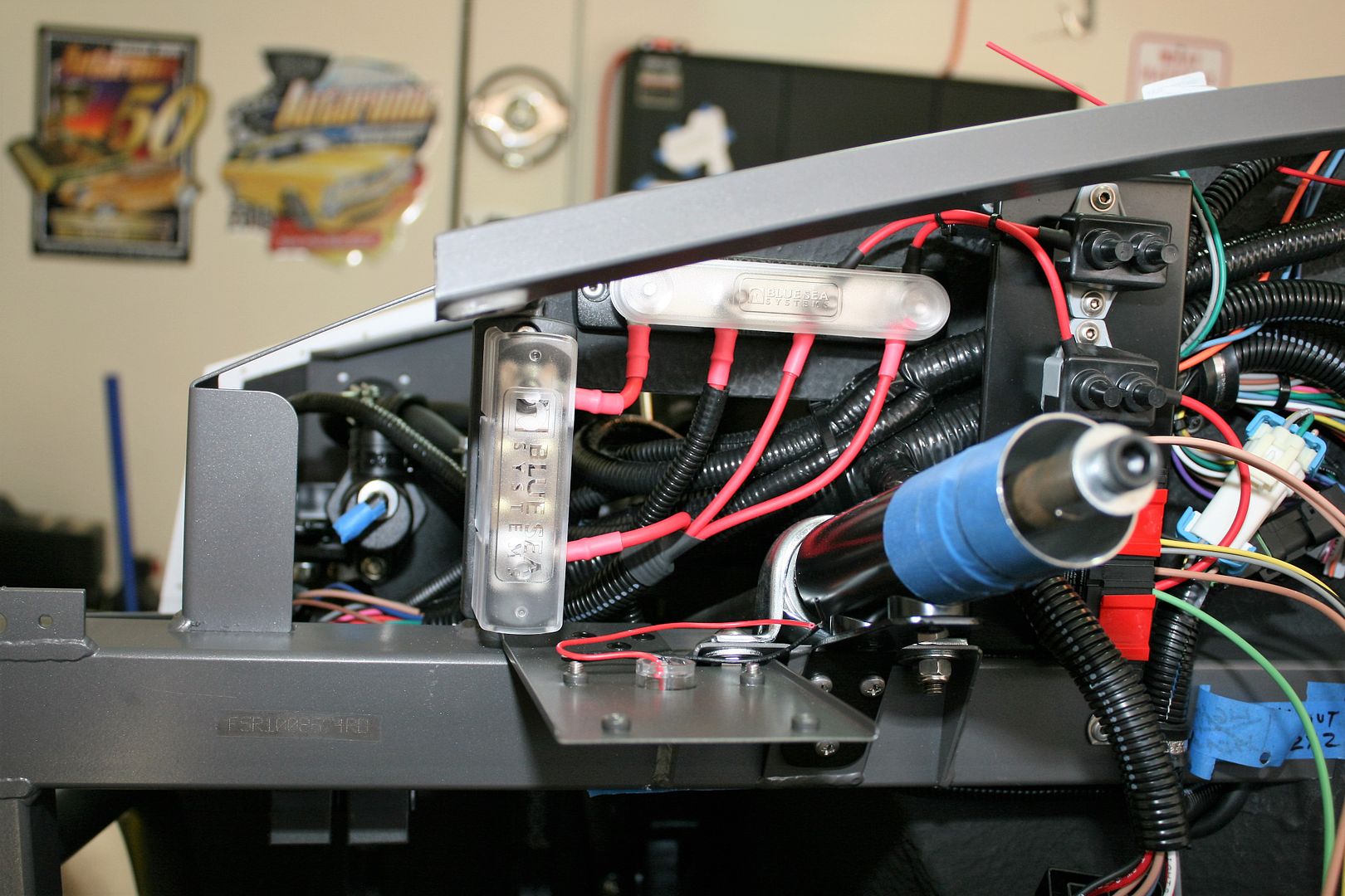
Again like my last build, I’m using an American Autowire headlight control module. This module handles the current of the headlights and low/high beam switching along with providing a flash to pass function. These were discussed some on the forum a couple years ago. Unfortunately, due to some failures, they were taken off the market and are no longer available. The failures were traced to interference from analog MSD ignition boxes (good old MSD takes it on the chin again…) and I’ve never had any issues with the same headlight control module and digital MSD box in #7750. But just in case I picked up a couple spares while they were still available, and will use one of them on this build. Since the module needs direct battery voltage, it has a separate circuit breaker. So I made a mounting bracket for the control module, circuit breaker, and another circuit breaker for the Tangent driving lights. The bracket allows the harness legs to pass behind it. The two circuit breakers get their +12V from the main power bus bar. The rear harness can be seen just below the headlight module.
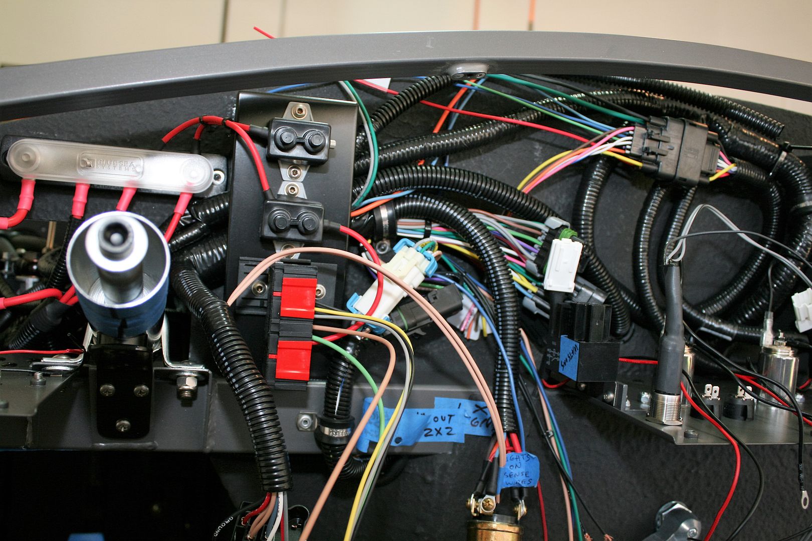
It’s not very pretty yet (probably never will be…) but this is how I’ve got the RF harness and the Coyote controls harness installed behind the dash. The connector at the top is from the Coyote harness. Still lots to do here to complete the point-to-point wiring and clean everything up.

The center dash brace also has quite a bit going on. Two auxiliary outlets, two switches for fuel pump and ignition, the previously shown Watson’s Streetworks headlight reminder and turn signal buzzer, and four relays. The relays use sense wires from the ignition and headlight switches for the headlight reminder, aux outlets, and running lights.
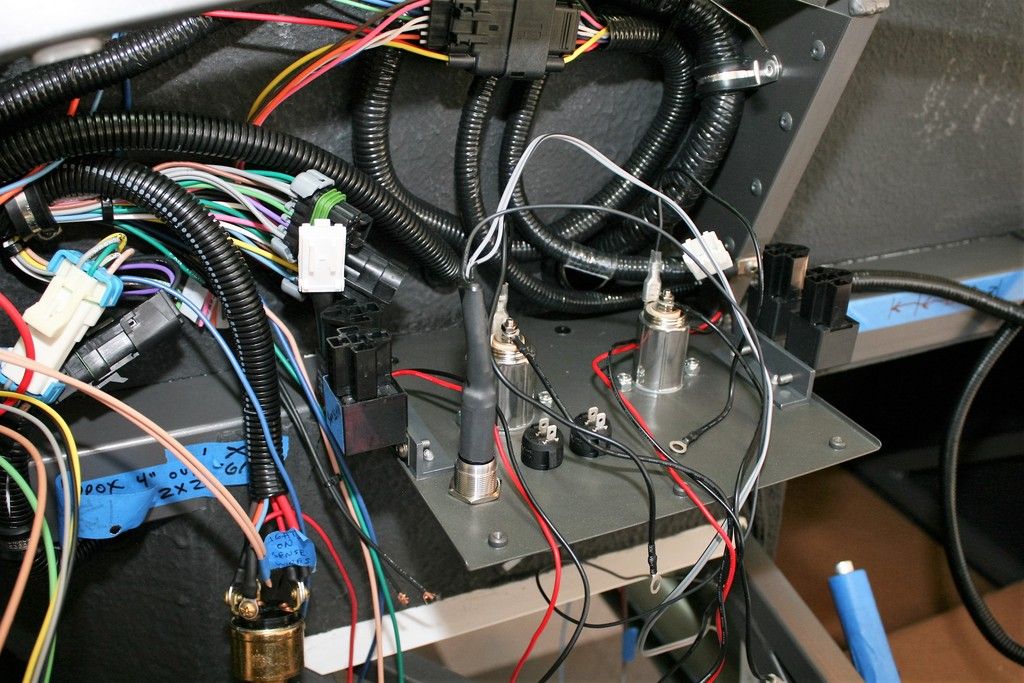
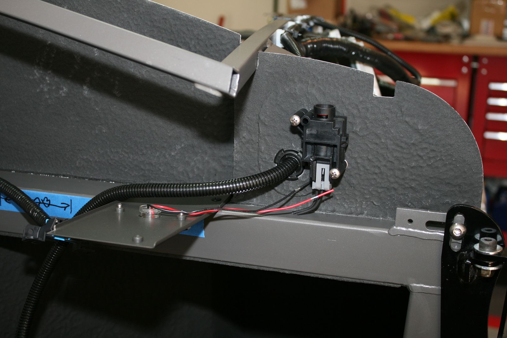
I ended up mounting the fuel pump inertia switch all the way over on the PS side firewall extension. It was just too crowded on the driver’s side. It’s relatively accessible behind the dash next to the glovebox. Barely visible in the LH side of the pic is the ODB connector that I'm installing on top of the 2x2 tube under the glovebox. Again just because it's crowded on the DS.
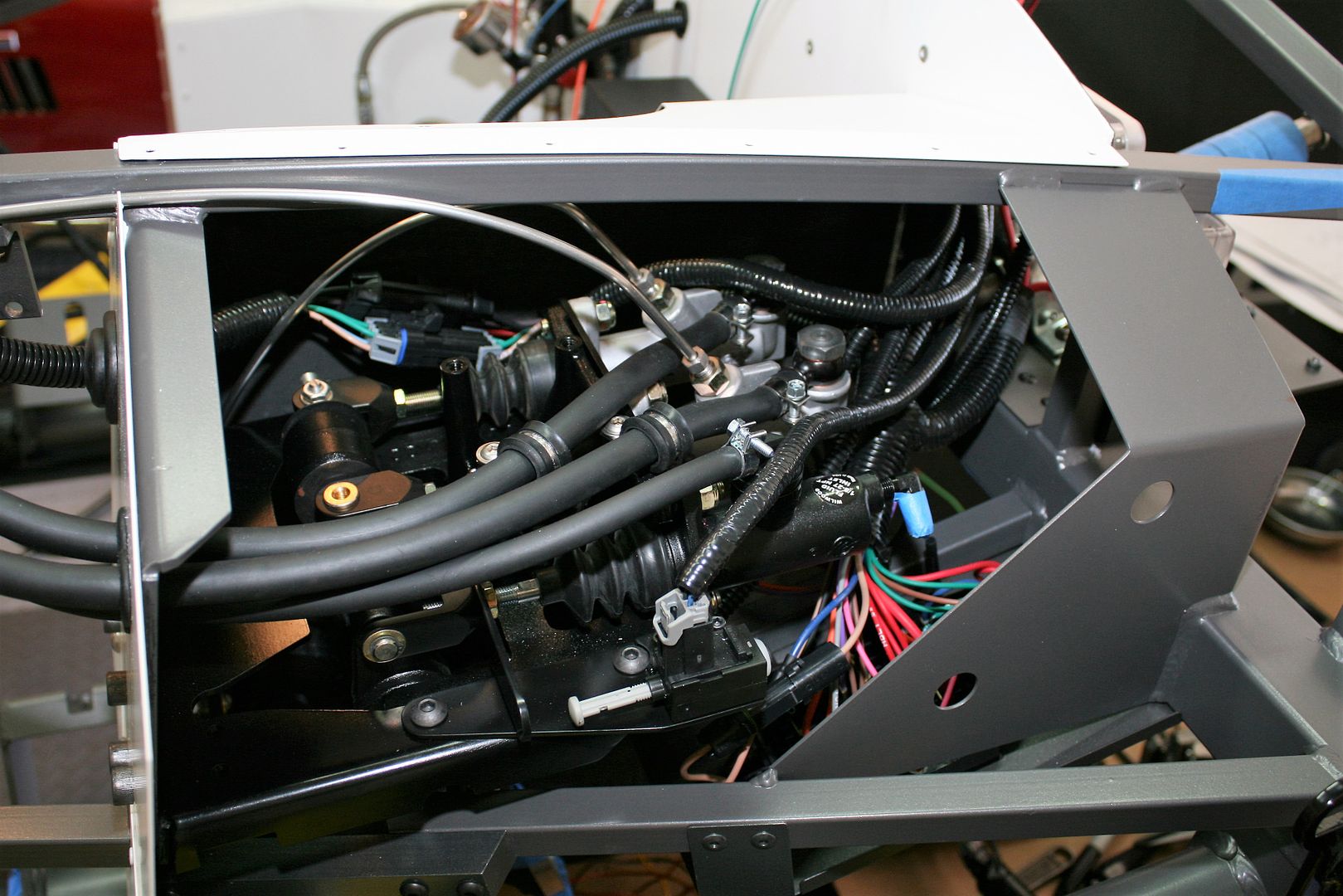
Finally, the DS footbox is 100% complete except for the flex line from the clutch MC to the slave. I’ll install that after the engine and trans are installed. All the wiring is installed including RF harness and fuse box, clutch and brake switches, front harness, DBW module, and RF and Coyote harness ground wires. The footbox is already narrowed from the stock version to provide space for the very wide Coyote engine. So this is a very busy place! But it’s all there now.
Last edited by edwardb; 04-15-2016 at 05:54 AM.
Build 1: Mk3 Roadster #5125. Sold 11/08/2014.
Build 2: Mk4 Roadster #7750. Sold 04/10/2017.
Build Thread
Build 3: Mk4 Roadster 20th Anniversary #8674. Sold 09/07/2020.
Build Thread and
Video.
Build 4: Gen 3 Type 65 Coupe #59. Gen 3 Coyote. Legal 03/04/2020.
Build Thread and
Video
Build 5: 35 Hot Rod Truck #138. LS3 and 4L65E auto. Rcvd 01/05/2021. Legal 04/20/2023.
Build Thread. Sold 11/9/2023.
 Posting Permissions
- You may not post new threads
- You may not post replies
- You may not post attachments
- You may not edit your posts
-
Forum Rules

Visit our community sponsor


 Reply With Quote