In my work as a computer programmer, I often need to think about problems at several different levels of abstraction. At the highest level, I'm writing a complete program to accomplish a certain set of goals. At progressively deeper levels, there are typically:
- Frameworks, where each is a large collection of many classes.
- Classes, where each is a collection of methods which, taken together, implement a specific feature or job.
- Methods, where each contributes to the overall feature or job of the class.
- Lines of code, where each implements a step of a method algorithm.
This certainly isn't the only way programs can be broken down, and this heirarchy describes the kind of code I write (end-user applications) in the language I typically write in (Objective-C). These details don't matter, nor does the terminology or technology.
However, the levels of abstraction do matter. When I'm writing code, I usually am focused on a particular one of these levels, but that doesn't mean I can forget about all the rest. The process of writing a program means repeatedly moving up and down this heirarchy to make sure that all levels are done right, and each relates well to its neighbors.
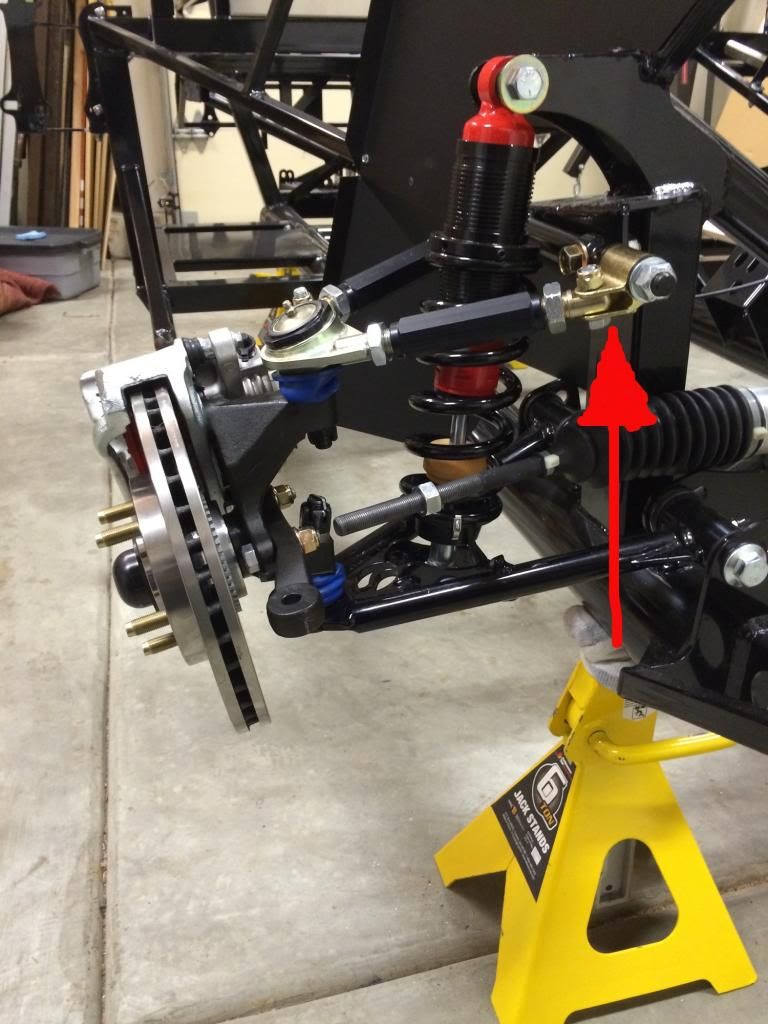
This works well for me in my job, and I'm trying to apply the same kind of heirarchical thinking to my Roadster build. After I took delivery of my kit and
started taking inventory, I was overwhelmed by the sheer number of parts and the random order in which they appeared. As I started in on the few steps in the assembly manual, I struggled just to find all the parts I needed to begin work.
It's taken about a month, but I'm getting more comfortable with thinking about my kit in terms of subsystems. Tonight, I began to sketch out a diagram which organizes the project into the major parts which make up the whole car. It's not complete (or even correct) yet, but it's a start.
kit-subsystems-v02.png

 Thanks:
  Likes:


 Reply With Quote