-
Not a waxer

Exciting times Paul!
Quick question; after adding the spacers what did your rear wheel mounting surface to mounting surface width wind up as? Time to start looking at wheel options...
Thanks,
Jeff
-
Senior Member


Originally Posted by
Jeff Kleiner

Exciting times Paul!
Quick question; after adding the spacers what did your rear wheel mounting surface to mounting surface width wind up as? Time to start looking at wheel options...
Thanks,
Jeff
Measured it just for you.  60-1/4 inches. That's with the Eibach 90.4.25.010.3 Pro-Spacer Wheel Spacer Kit, 25mm (1 inch) parts I'm using.
Last edited by edwardb; 08-28-2018 at 08:19 PM.
Build 1: Mk3 Roadster #5125. Sold 11/08/2014.
Build 2: Mk4 Roadster #7750. Sold 04/10/2017.
Build Thread
Build 3: Mk4 Roadster 20th Anniversary #8674. Sold 09/07/2020.
Build Thread and
Video.
Build 4: Gen 3 Type 65 Coupe #59. Gen 3 Coyote. Legal 03/04/2020.
Build Thread and
Video
Build 5: 35 Hot Rod Truck #138. LS3 and 4L65E auto. Rcvd 01/05/2021. Legal 04/20/2023.
Build Thread. Sold 11/9/2023.
-
Not a waxer
Originally Posted by
edwardb
Measured it just for you.
60-1/4 inches. That's with the Eibach 90.4.25.010.3 Pro-Spacer Wheel Spacer Kit, 25mm (1 inch) parts I'm using.
Thank you! Very much appreciated 
Jeff
-
Senior Member
Lizard Skin
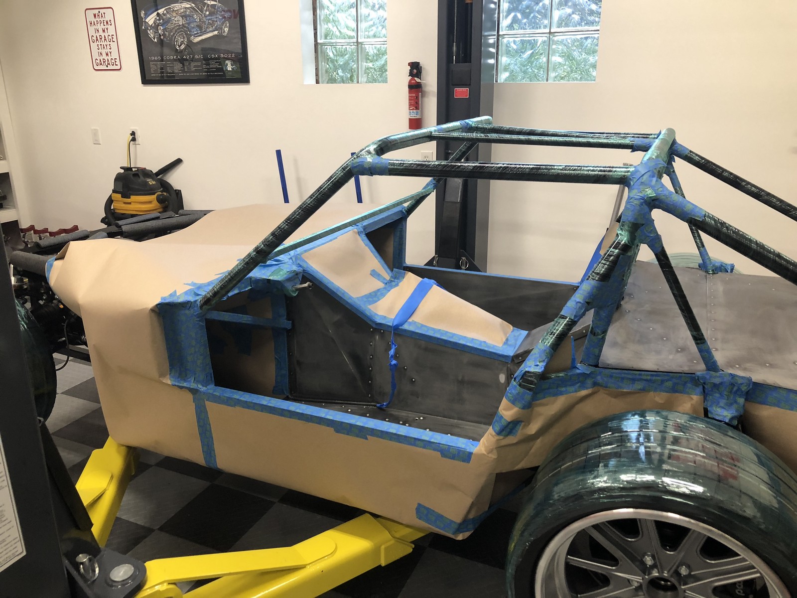
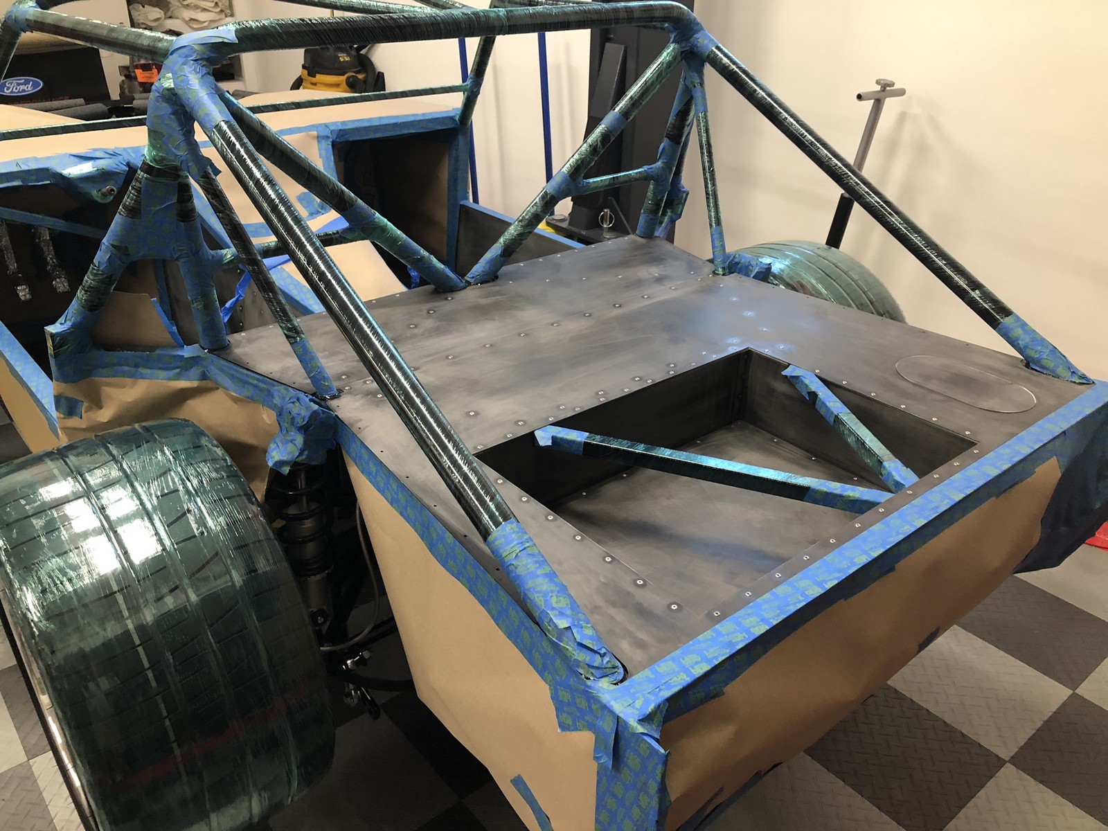
Today I finished spraying Lizard Skin heat and sound insulation and got everything de-masked. Theres no sugar-coating it. Lizard Skin is a lot of work. I really like the final result, so stayed focused on that. Takes a while to get everything properly masked, then two separate days of spraying (24 hours between the sound and heat products), then clean everything up. Ive done the previous Roadsters in my garage. Even though I was careful, and spread lots of drop clothes, still managed to sling the stuff all over the place including on the walls on the other side of the garage. The undercoat gun used for this application, along with the jelly like viscosity of the material, makes it interesting. So this time I chose to spray outside on my driveway on a great big tarp. The backdrop was the woods along the side of my driveway. So not too worried about that. Was a good plan until zero chance of precipitation turned into a shower just as I was pushing the finished chassis back into the garage. Didnt hurt anything but would have been a disaster if 20-30 minutes earlier.
As far as the actual process, I followed Lizard Skins instructions, as I have before. I did a write-up a few years ago. Pretty much followed my own recommendations. https://www.ffcars.com/forums/17-fac...xperience.html. The Coupe is a little challenging, as Ive mentioned before, because of the number of panels that dont get installed until after the body is on. Plus theres the roll cage to mask off. In a previous update, I described using stick-on materials in the footwells. So the Lizard Skin application was the balance of the cockpit, the hatch area, and the loose pieces to be installed later. I sprayed two coats of sound material on everything yesterday. Then 2 coats of heat material in the cockpit and loose cockpit parts and one coat in the hatch area and loose hatch parts. Ive got just enough left over from the 2 gallon bucket of each product to spray the body headliner area. Would like to cut down on sound and mostly heat by spraying there when I get to body work.
Thats about it. Here are a bunch of pictures. First scuffed up my nice pretty powder coat where the Lizard Skin would be applied. Before anyone questions, the other side in all cases is still still shiny new powder coat and in my world is showing.  I used stretch wrap film around the roll bars. That worked pretty well and I think was easier then a lot of masking tape or paper. At the last minute, decided to also put some stretch wrap film around my brand new tires since they would be rolling around where I was spraying. Glad I did. They picked up a lot of overspray material. The rest of the masking was the usual mixture of tape, paper, etc. Those are the wires for my heated seats that are wrapped and hanging out of the way.


Out on the driveway while spraying:

Last edited by edwardb; 08-28-2018 at 04:46 PM.
Build 1: Mk3 Roadster #5125. Sold 11/08/2014.
Build 2: Mk4 Roadster #7750. Sold 04/10/2017.
Build Thread
Build 3: Mk4 Roadster 20th Anniversary #8674. Sold 09/07/2020.
Build Thread and
Video.
Build 4: Gen 3 Type 65 Coupe #59. Gen 3 Coyote. Legal 03/04/2020.
Build Thread and
Video
Build 5: 35 Hot Rod Truck #138. LS3 and 4L65E auto. Rcvd 01/05/2021. Legal 04/20/2023.
Build Thread. Sold 11/9/2023.
-
Post Thanks / Like - 0 Thanks, 1 Likes
-
Senior Member
Lizard Skin (continued)
Finished product. You can kind of see where the rain drops hit. May go away once it’s completely dry. Or not. Don't think it's an issue.

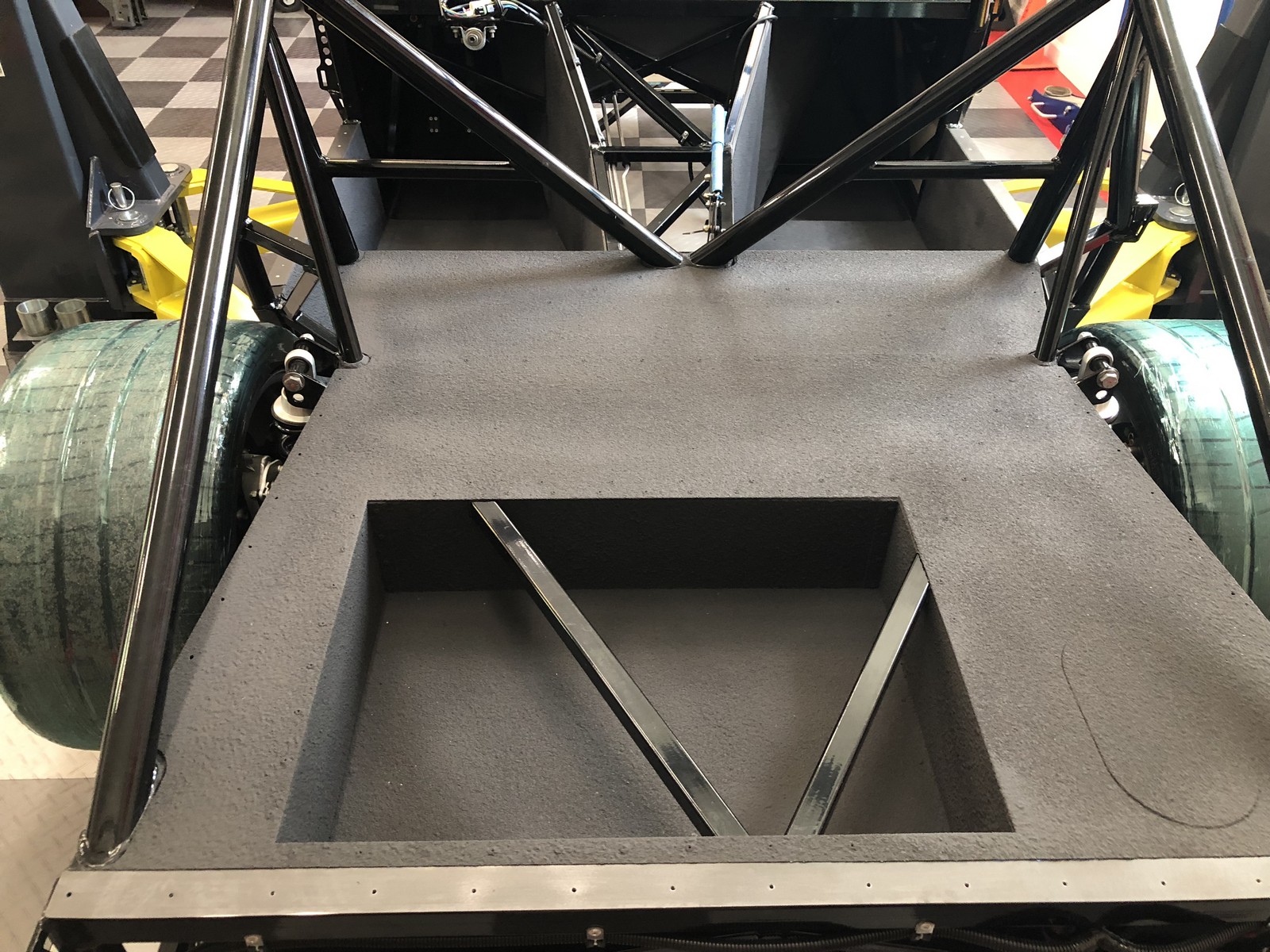
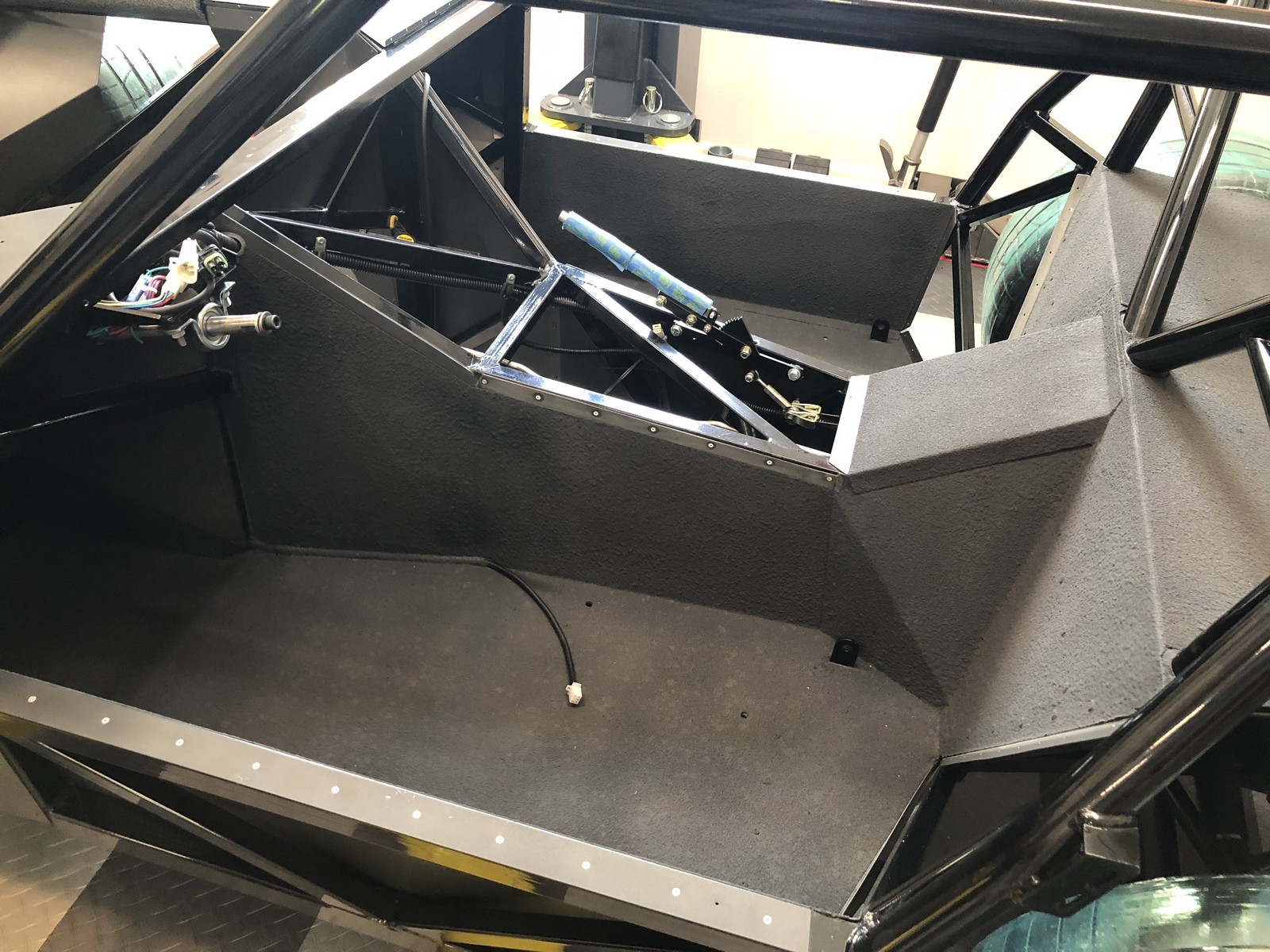

Now onward to electrical, engine, etc. And finally can start leaving things in once installed.
Last edited by edwardb; 08-28-2018 at 04:39 PM.
Build 1: Mk3 Roadster #5125. Sold 11/08/2014.
Build 2: Mk4 Roadster #7750. Sold 04/10/2017.
Build Thread
Build 3: Mk4 Roadster 20th Anniversary #8674. Sold 09/07/2020.
Build Thread and
Video.
Build 4: Gen 3 Type 65 Coupe #59. Gen 3 Coyote. Legal 03/04/2020.
Build Thread and
Video
Build 5: 35 Hot Rod Truck #138. LS3 and 4L65E auto. Rcvd 01/05/2021. Legal 04/20/2023.
Build Thread. Sold 11/9/2023.
-
Paul,
Could you tell me what the panels is to the left of the firewall extension, the one that has a similar shape as the dash panel? It looks foreign to me but it may be a customer piece that you made.
Thank you,
Mike
-
Senior Member
Originally Posted by
MC Builders
Paul,
Could you tell me what the panels is to the left of the firewall extension, the one that has a similar shape as the dash panel? It looks foreign to me but it may be a customer piece that you made.
Thank you,
Mike
Hi Mike. Can you post a picture or point to a post that shows what you're describing? I don't recall fabricating any parts in the area you described. Looked through my pictures to confirm. I did modify how the parts on the dash attach, e.g. made all the fasteners hidden. But used kit parts.
Build 1: Mk3 Roadster #5125. Sold 11/08/2014.
Build 2: Mk4 Roadster #7750. Sold 04/10/2017.
Build Thread
Build 3: Mk4 Roadster 20th Anniversary #8674. Sold 09/07/2020.
Build Thread and
Video.
Build 4: Gen 3 Type 65 Coupe #59. Gen 3 Coyote. Legal 03/04/2020.
Build Thread and
Video
Build 5: 35 Hot Rod Truck #138. LS3 and 4L65E auto. Rcvd 01/05/2021. Legal 04/20/2023.
Build Thread. Sold 11/9/2023.
-
Senior Member

Great job Paul!! Have to love Michigan weather, If you don't like how it is now wait 10 mins!!!!
Higgy
MK4 #11012 picked up 04/16/24
351W, 3 link, single roll bar
MK4 #10616 picked up 4/10/23
302w, 4 link, 17's, dual roll bar SOLD
MK4 #9759 picked up on 4/3/19
351C, 3 link, 17's, dual roll bars SOLD
-
Senior Member
Gen 3 Coyote in the House
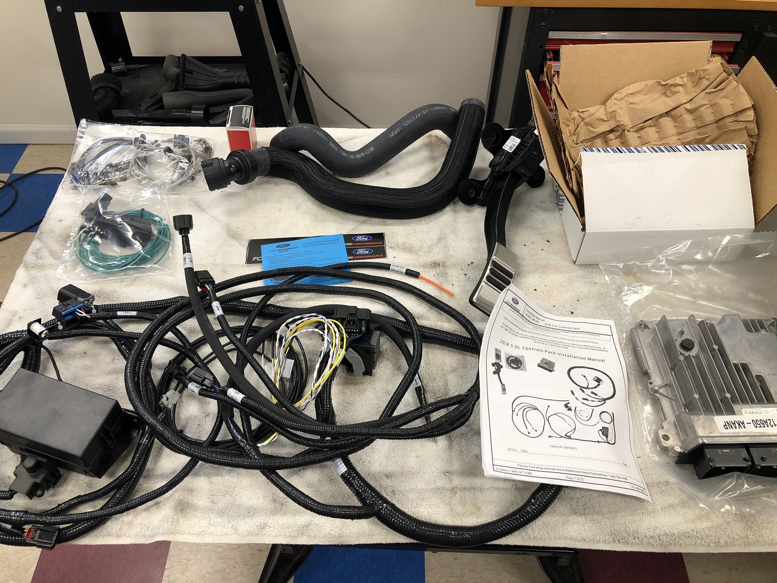
Look what showed up in my garage workshop today.

If you've been following this build thread, no secret my goal has been to use the new Gen 3 Coyote crate. Over the months I’ve been following the progress closely as Ford Performance prepared for its release. I was able to establish a contact at Ford Performance who has been very gracious to let me know the status whenever I asked. They are still a couple weeks away from general public release. But late last week I was given the opportunity to purchase a Gen 3 engine and control pack in advance of the general release. Working through a dealer I completed the deal. No surprise the Gen 3 is more expensive. Yesterday the control pack was delivered. Today the engine itself. I’m just starting to digest the new instructions and what differences I’ve uncovered so far. But thought I'd throw some pictures out there. My plan right now is to drop just the engine into the Coupe chassis, like I did with #8674, to determine and finalize the best routing and layout for everything. I’ll get going on that right away.
The control pack is pretty similar to the Gen 2. Same PDB and a lot of the same connections. Same exact DBW pedal. Just one clutch switch like the later Gen 2’s. Combined ODB2 plug and MIL also like later Gen 2’s. And also simpler power connection, also as I believe is on later Gen 2’s. Differences I’ve noticed so far: The overall harness is much simpler and shorter than the early Gen 2 I have in #8674. Should fit without a lot of extra. The pigtail connection has been slimmed down to just three wires. Fuel pump, start sense, ignition sense. Still no tach wire. I asked Ford about this and they told me starting in 2015 the PCM’s didn’t have a proper tach signal for aftermarket gauges. So back to tapping one of the coil wires like before. The O2 sensors have their own harness. Unlike the Gen 2 that were attached to the engine. The instructions describe setting the fuel regulator at 65 PSI vs. 55 on the previous models. I’m guessing because of the added direct injection? But it has its own pump on the engine. Who knows. One big difference is the Bosch PCM vs the Continental PCM from before. My old company lost the contract I guess. I didn’t put the two side-by-side. But it does appear slightly larger. From what I hear at Ford Performance, a lot going on there compared to before with the additions to the Gen 3. I’ll describe more as I learn more and proceed with the installation. But here’s a pic with the parts received. The stock air box pieces are still in the box. Other than the MAF sensor, nothing usable. Too bad.
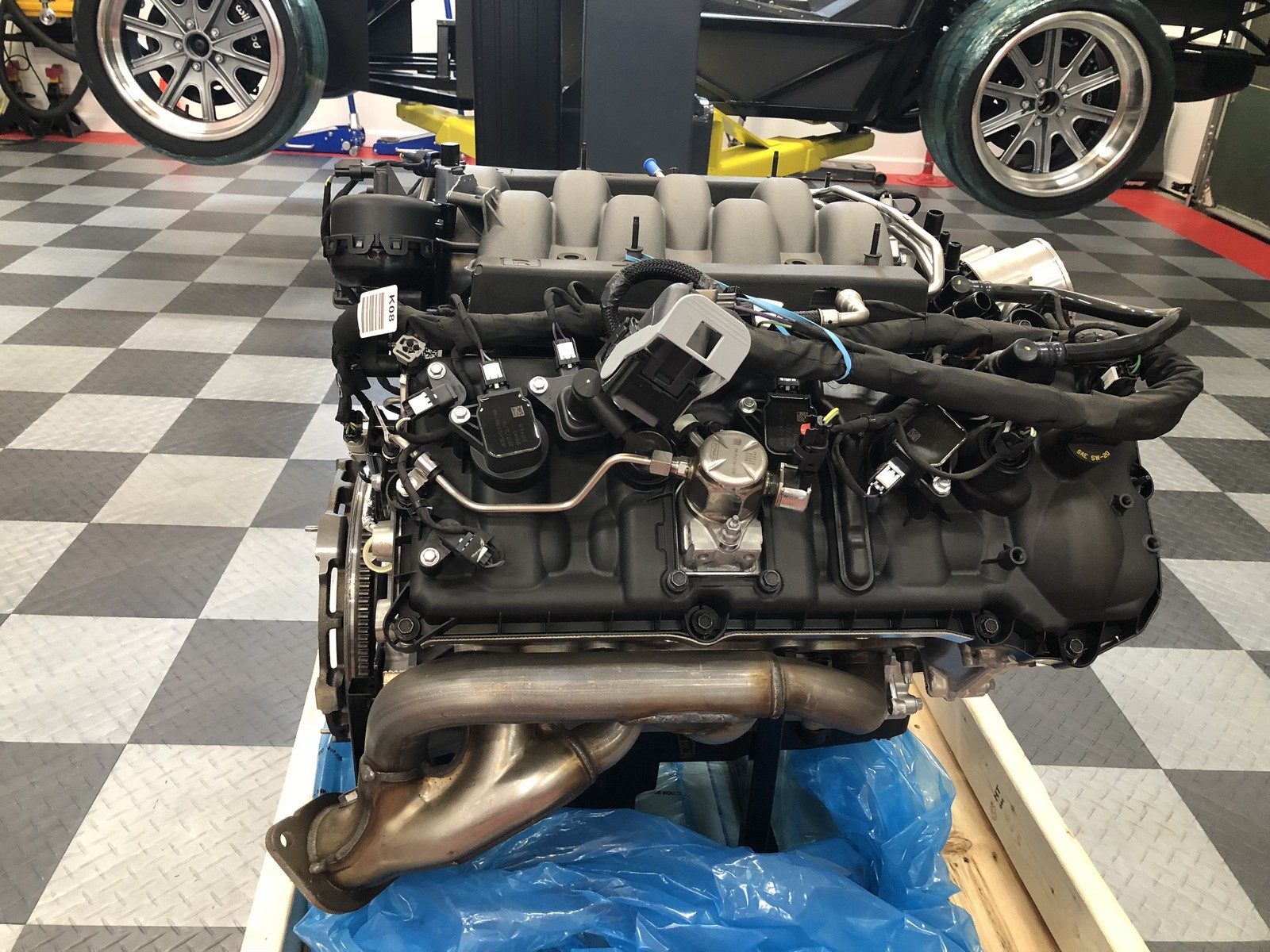
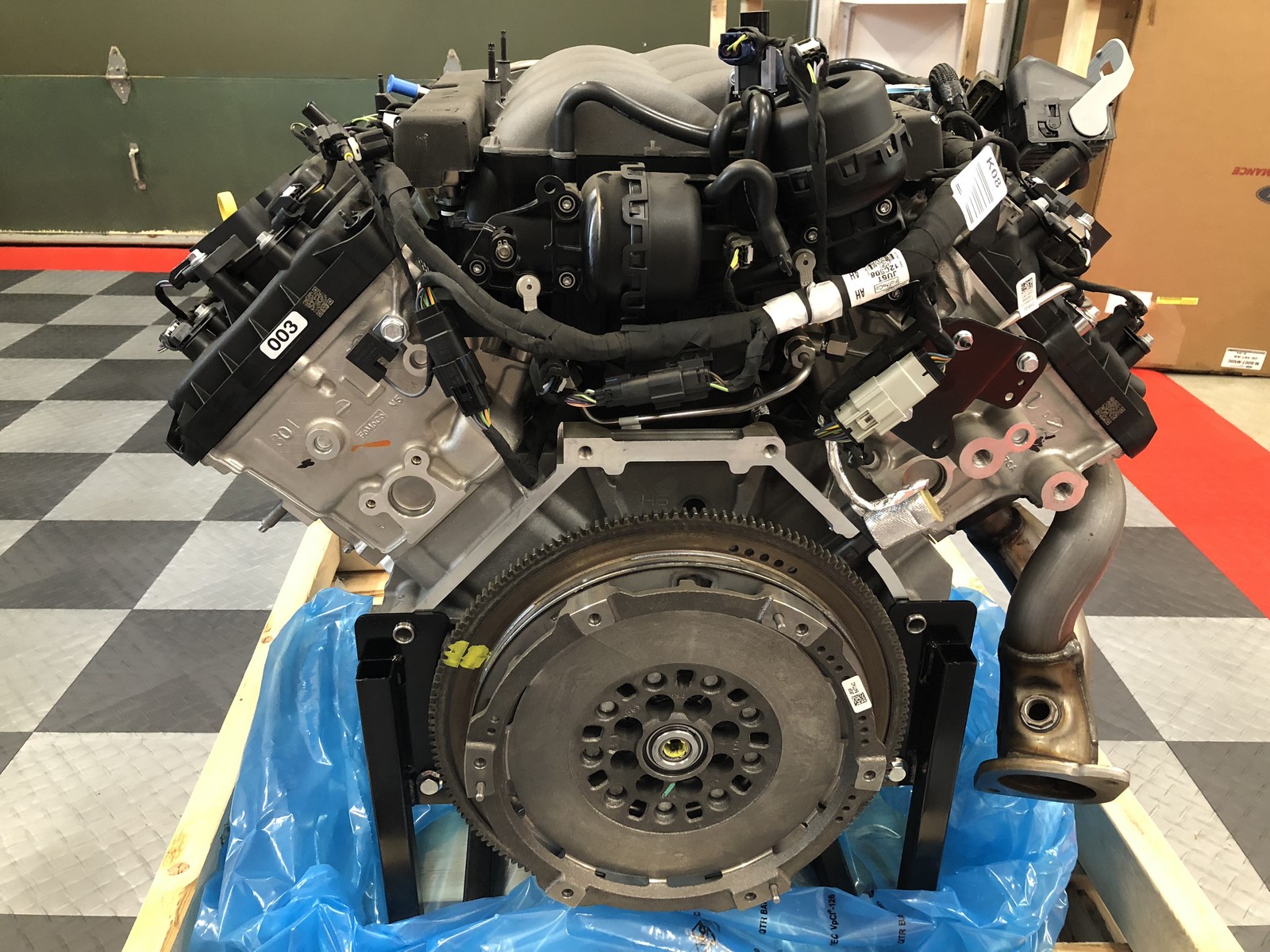
The engine itself I’d seen before at Autorama and also posted pictures. But a little different now that it’s actually in my garage. Not a lot to say at this point since I literally just unwrapped it a couple hours ago. Nice to see Ford shipped it with a proper engine cradle vs. blocks on the skid. Some new plumbing to figure out. Looks like the CMCV setup is plumbed differently. That was a subject of a bunch of forum posts with the Gen 2. Looks like we’ll get to start that again! Obviously the top of the heads are now completely covered with wiring, plumbing, etc. because of the DI. Most have seen the new UFO looking engine cover for the Gen 3. Will think about what to do after it’s in the chassis. One major thing I noticed, and I hadn’t learned about this before, is that the 2018 Mustang manual setup has a dual mass flywheel and twin disc clutch. You can see the different flywheel in the pics. Will have to figure out what this means. Nice upgrade, but hopefully doesn’t affect my already on-hand QuickTime bell housing and Tilton hydraulic throw-out bearing. I purchased the Coyote engine lift brackets offered on the forum by TD Motion. Decided those would work better than the homemade ones I used before. Just bolted them on and they fit perfectly. Here are pictures and will provide more updates later as I dig into it.


Last edited by edwardb; 08-29-2018 at 12:29 PM.
Build 1: Mk3 Roadster #5125. Sold 11/08/2014.
Build 2: Mk4 Roadster #7750. Sold 04/10/2017.
Build Thread
Build 3: Mk4 Roadster 20th Anniversary #8674. Sold 09/07/2020.
Build Thread and
Video.
Build 4: Gen 3 Type 65 Coupe #59. Gen 3 Coyote. Legal 03/04/2020.
Build Thread and
Video
Build 5: 35 Hot Rod Truck #138. LS3 and 4L65E auto. Rcvd 01/05/2021. Legal 04/20/2023.
Build Thread. Sold 11/9/2023.
-
Post Thanks / Like - 2 Thanks, 1 Likes
-
glad to see your gen three coyote has arrived. I ordered my coupe and have a 9-30-18 build date. delivery to Fort Wayne should be by oct 10. I ordered with the coyote engine mount so will be closely following your install process. looking forward to following your progress.
-
Senior Member
Originally Posted by
kehenline
glad to see your gen three coyote has arrived. I ordered my coupe and have a 9-30-18 build date. delivery to Fort Wayne should be by oct 10. I ordered with the coyote engine mount so will be closely following your install process. looking forward to following your progress.
Hello to Fort Wayne. Spent a number of years there through two different job stints. Both of our sons were born there and graduated from Northrop High School. Congrats on your upcoming Coupe delivery and build. You're in for a great adventure. Coyote uses the same mounts as other supported engines. But lots of part differences of course.
Build 1: Mk3 Roadster #5125. Sold 11/08/2014.
Build 2: Mk4 Roadster #7750. Sold 04/10/2017.
Build Thread
Build 3: Mk4 Roadster 20th Anniversary #8674. Sold 09/07/2020.
Build Thread and
Video.
Build 4: Gen 3 Type 65 Coupe #59. Gen 3 Coyote. Legal 03/04/2020.
Build Thread and
Video
Build 5: 35 Hot Rod Truck #138. LS3 and 4L65E auto. Rcvd 01/05/2021. Legal 04/20/2023.
Build Thread. Sold 11/9/2023.
-
thanks, paul. this will be a new experience for me and I appreciate your encouragement. Northrup is still running strong!
-
Senior Member

So cool! Glad to see it fit perfectly into your build timeline!
I have a McLeod twin disk clutch setup ready for mine and it's supposed to fit in the same Quicktime bellhousing. With the Tilton being adjustable, I think you're safe.
Gen 3 Type 65 Coupe builder
-
Top Notch Builder

So its definitely not the prettiest engine ever. Any ideas on how youll tackle the aesthetics? Sorry but I have to ask. Im in the same boat. Im imagining how to make this look right and you are miles ahead of me so whats your thoughts?
-
Senior Member
Originally Posted by
P100DHG
So it’s definitely not the prettiest engine ever. Any ideas on how you’ll tackle the aesthetics? Sorry but I have to ask. I’m in the same boat. I’m imagining how to make this look right and you are miles ahead of me so what’s your thoughts?
You're right. It's not going to win any beauty contests. Especially not at this stage. But then neither were the previous Coyote versions. Like most modern computer controlled EFI engines, there are wires and hoses all over the place. With the added direct injection (DI) on the Gen 3, there are even more. No longer possible to use coil covers as on previous Coyotes. Which helped some and could themselves be dress-up pieces. Note that in the one side view picture, the PCM harness connection is just draped over the head. That won't be there or nearly as visible once the engine is installed. But to your point, I don't have too many thoughts about this yet. I'm going to get the engine into the chassis and see how much really shows. That makes a difference. I'm not expecting to use Ford's new top cover. At least not in stock form. There's even more going on in the basically wide open Coupe engine compartment. Once the front cowl is raised. A/C hoses, heater hoses, radiator hoses, battery cables, chassis wiring, the list goes on. It's going to be a busy place no matter what. I'll do my best to keep it all neat and organized and see where it goes from there. Not much else to say at this point.
Build 1: Mk3 Roadster #5125. Sold 11/08/2014.
Build 2: Mk4 Roadster #7750. Sold 04/10/2017.
Build Thread
Build 3: Mk4 Roadster 20th Anniversary #8674. Sold 09/07/2020.
Build Thread and
Video.
Build 4: Gen 3 Type 65 Coupe #59. Gen 3 Coyote. Legal 03/04/2020.
Build Thread and
Video
Build 5: 35 Hot Rod Truck #138. LS3 and 4L65E auto. Rcvd 01/05/2021. Legal 04/20/2023.
Build Thread. Sold 11/9/2023.
-
Senior Member
Gen 3 Coyote Fitment
Have spent some hours since checking how things fit after receiving the Gen 3 Coyote yesterday. This is where the excitement of doing something new meets with reality. Still a long ways to go, but thought I’d post what I’ve learned so far. Some things seem OK. But a couple of challenges. Open to suggestions here!!!
First the good. Energy Suspension motor mounts, QuickTime bell housing, A/C compressor, Moroso oil pan bolt pattern, all fit OK based on actual assembly check. Exhaust headers, starter motor, alternator, location for KRC power steering, radiator and heater and PCV hose locations and connections all LOOK exactly the same comparing to the Gen 2 Coyote in #8674. Obviously I’ll be checking with real parts once received. But looks OK for now. I’ll also mention I studied the vacuum connections on the CMCV setup, and it appears to be connected to a vacuum source right from the factory. I'll need to confirm, but looks like this won’t be something that needs to be addressed on the Gen 3. This has tripped up and confused a lot of builders before. Now hopefully no longer. I removed the oil cooler, like was necessary before. That also is exactly the same needing the shorter oil filter adapter. I also learned from my last build and caught all the oil in a brand new 5 gallon plastic pail with a sealing lid. Just over 2-1/2 gallons drained out. I’ll put it back in once the engine is installed. That’s $50 or so of 5w-20 synthetic oil that I didn’t make allowances to save the last time. Lesson learned.
Now for the challenges. I’ve uncovered two (so far…) and both are relatively significant.
1. The dual mass flywheel (already installed from the factory) and twin disc clutch (purchased separately) new with the Gen 3 Coyote will NOT work with my already purchased QuickTime bell housing and T-56 transmission. The input shaft on the T-56 is 4.5625 inches from the face of the bell housing to where the shaft would be against the race of the pilot bearing. With the QuickTime RM-8080 bell housing on the engine, that same distance with the dual mass flywheel is 3.375 inches. A difference of 1.1875 and no possible way to work. The RM-8080 bell is the only option for the Coyote + T-56 combination at this time. The GM version of the T-56 (the only other one available) is almost an inch longer input than the Ford version I have. So no relief on either front right now. My plan at the moment is to remove the dual mass flywheel and replace with a M-6375-M50 billet flywheel like I used on #8674. I’m HOPING the crankshaft has the same 8-bolt connection underneath the currently installed dual mass flywheel and the usual pocket for the pilot bearing. The bolts are large Torx heads that I don’t have a bit for. I’ll get to the store tomorrow and get them off. Holding my breath. I’m happy with the Ford Performance billet flywheel and clutch (dual friction Centerforce part) in #8674, so as long as it fits I’ll be OK with it. Maybe the dual mass flywheel has some eBay or Craigslist value.
2. I was warned about this one, and turned out to be true. Like most everyone doing Coyote builds, I used the low profile Moroso 20570 with Moroso 24570 pickup on #8674. Had the same parts ready to go and now have found Ford has changed the oil pump on the Gen 3 Coyote. No longer uses a bolt-on pickup but instead a slip-in fitting that’s part of the new composite oil pan. Additionally, the new oil pan has the windage tray/pan gasket as part of the pan where it was separate before. Easy enough to buy and install the windage tray/gasket. Not so easy on the pickup. I just sent a message to Moroso asking if they have plans to offer a new/updated pickup. Not optimistic, at least in the short term, but see what happens. Might be possible to modify the current Moroso piece, but haven’t studied that yet. Need to proceed with caution here as an improper connection would quickly destroy the engine. I'm going to leave the stock pan on the engine when I do my initial mock-up, so I'll see just how far it hangs below the frame. Expecting that to be a no-go, but I'll check. So no answer on this one yet. Here are couple pictures.
Current Moroso parts with Gen 3 oil pan.
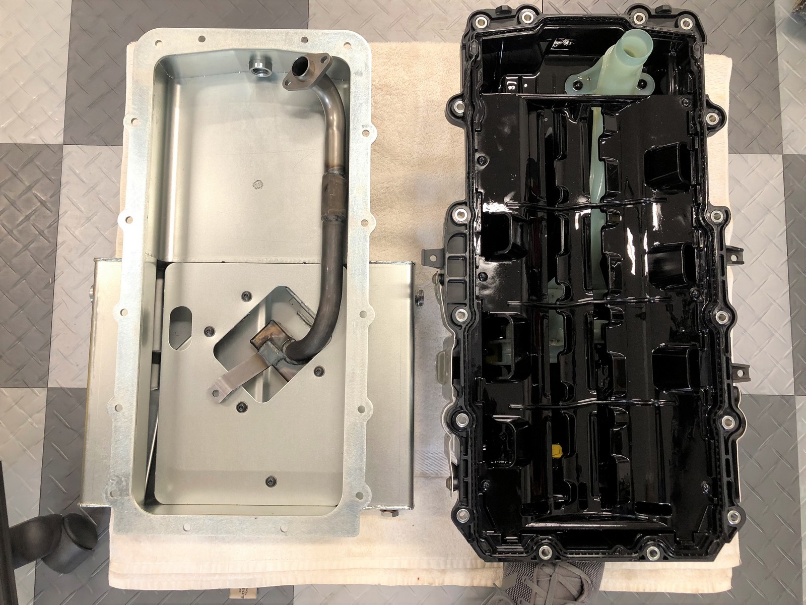
Underside of Gen 3 engine showing new pump and pickup.

Last edited by edwardb; 08-30-2018 at 04:15 PM.
Build 1: Mk3 Roadster #5125. Sold 11/08/2014.
Build 2: Mk4 Roadster #7750. Sold 04/10/2017.
Build Thread
Build 3: Mk4 Roadster 20th Anniversary #8674. Sold 09/07/2020.
Build Thread and
Video.
Build 4: Gen 3 Type 65 Coupe #59. Gen 3 Coyote. Legal 03/04/2020.
Build Thread and
Video
Build 5: 35 Hot Rod Truck #138. LS3 and 4L65E auto. Rcvd 01/05/2021. Legal 04/20/2023.
Build Thread. Sold 11/9/2023.
-
Paul - is that a plastic pickup tube on the factory pan? Wow. Four-bolt mains next to a plastic pick-up tube. I wonder if that's standard practice in the automotive industry these days?
-
Senior Member
Originally Posted by
edwardb
1. The dual mass flywheel (already installed from the factory) and twin disc clutch (purchased separately) new with the Gen 3 Coyote will NOT work with my already purchased QuickTime bell housing and T-56 transmission. The input shaft on the T-56 is 4.5625 inches from the face of the bell housing to where the shaft would be against the race of the pilot bearing. With the QuickTime RM-8080 bell housing on the engine, that same distance with the dual mass flywheel is 3.375 inches. A difference of 1.1875 and no possible way to work. The RM-8080 bell is the only option for the Coyote + T-56 combination at this time. The GM version of the T-56 (the only other one available) is almost an inch longer input than the Ford version I have. So no relief on either front right now. My plan at the moment is to remove the dual mass flywheel and replace with a M-6375-M50 billet flywheel like I used on #8674. I’m HOPING the crankshaft has the same 8-bolt connection underneath the currently installed dual mass flywheel and the usual pocket for the pilot bearing.
Hmm, that is interesting. It looks like Ford decided to move the pilot bearing to the center mass location of the dual clutch flywheel. Maybe a bit strange but I can understand how that would support the longer flywheel and clutch better. I'll have to take a look at my twin disk clutch and see if I can spot the differences. Maybe it's the fact that it's a dual mass flywheel that is causing the extra length even with it looking 'dished'
Gen 3 Type 65 Coupe builder
-
Senior Member
Originally Posted by
q4stix
Hmm, that is interesting. It looks like Ford decided to move the pilot bearing to the center mass location of the dual clutch flywheel. Maybe a bit strange but I can understand how that would support the longer flywheel and clutch better. I'll have to take a look at my twin disk clutch and see if I can spot the differences. Maybe it's the fact that it's a dual mass flywheel that is causing the extra length even with it looking 'dished'
That's definitely the reason my bell housing/T-56 combination won't work. The pilot bearing is moved way out. Confirmed today by taking it apart. See the following update.
Last edited by edwardb; 08-31-2018 at 08:54 PM.
Build 1: Mk3 Roadster #5125. Sold 11/08/2014.
Build 2: Mk4 Roadster #7750. Sold 04/10/2017.
Build Thread
Build 3: Mk4 Roadster 20th Anniversary #8674. Sold 09/07/2020.
Build Thread and
Video.
Build 4: Gen 3 Type 65 Coupe #59. Gen 3 Coyote. Legal 03/04/2020.
Build Thread and
Video
Build 5: 35 Hot Rod Truck #138. LS3 and 4L65E auto. Rcvd 01/05/2021. Legal 04/20/2023.
Build Thread. Sold 11/9/2023.
-
Senior Member
Gen 3 Mock-Up Started plus Updates
Today I was able to get the Gen 3 Coyote into the Gen 3 Coupe chassis. All by myself. But then no flywheel, clutch, bell housing or transmission. Just the engine itself. So that’s cheating. I’ll definitely get help when it’s time to put the whole thing in. But this let’s me work on placement for everything in the engine compartment. Glad I’m taking this step because things are pretty tight.
What I learned today: In general, the fit isn’t as tight as the Roadster. It’s close to sheet metal in a few places, but nothing like the clearances in the Roadster. Exhaust header bolt access is pretty open on the passenger side, and all but the very back one on the drivers side also pretty accessible. For now I’m going to leave the original studs. The only one in question will be that back one on the DS. May shorten it or just use a regular bolt for that one spot. Oil filter is accessible. Without the factory cooler of course. Front dress on the engine (alternator, PS, A/C) all open and accessible. Starter motor also is fine. The direct injection (DI) pump on the PS head, discussed at some length in earlier posts, clears OK. Amazingly similar to the computer generated plots from Factory Five I posted. But the connector body attached to it was pretty hard against the top chassis rail as the engine was going down. So chose to move it out of the way to not damage anything. It’s a diaphragm style pump with a plunger that's actuated by the cam. With the two nuts removed, and the attached fuel line, lifts out of the way pretty easily. Once the engine is in, goes back together and clears everything just fine.
Over the next days I’ll be determining locations for the remaining components. I don’t see any choice but to put the PCM on the PS above the headers. Same as typically done with the Roadster. Will be congested over there with heat and A/C lines and components. But don’t see any other options. With the Roadster, it was necessary to remove the steering shaft when dropping in the Coyote. With this Coupe, not a hard interference point. I didn’t move it this time. But it’s a little bit in the way and will move it out of the way in the next round. The PDB will be somewhere on the firewall or foobox corners. Tight but should fit. Fuel pump regulator will be on the corner of the DS footbox. Not much else to say. Lots of work ahead now getting this done and as neat and orderly as possible.
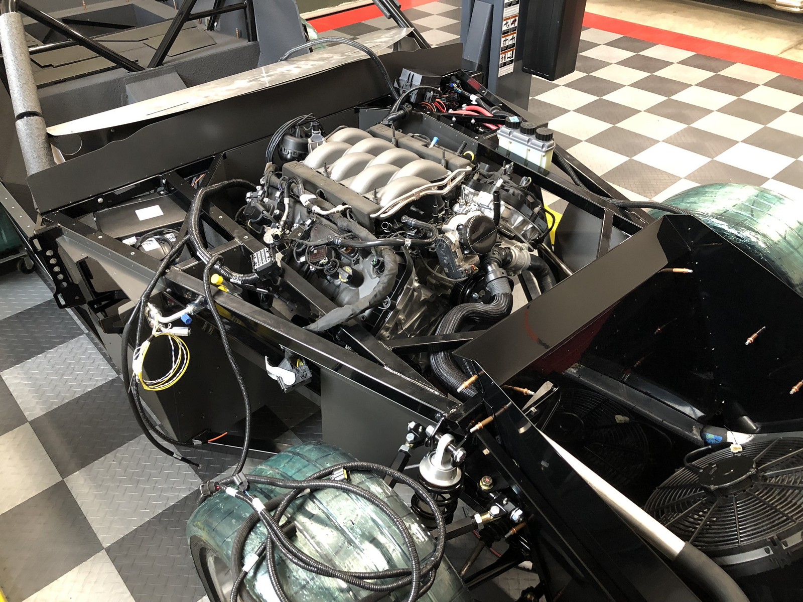
Here are pictures from all sides. Similar to other builds with the Coyote engine. Just the added spaghetti from the Gen 3 Coyote.

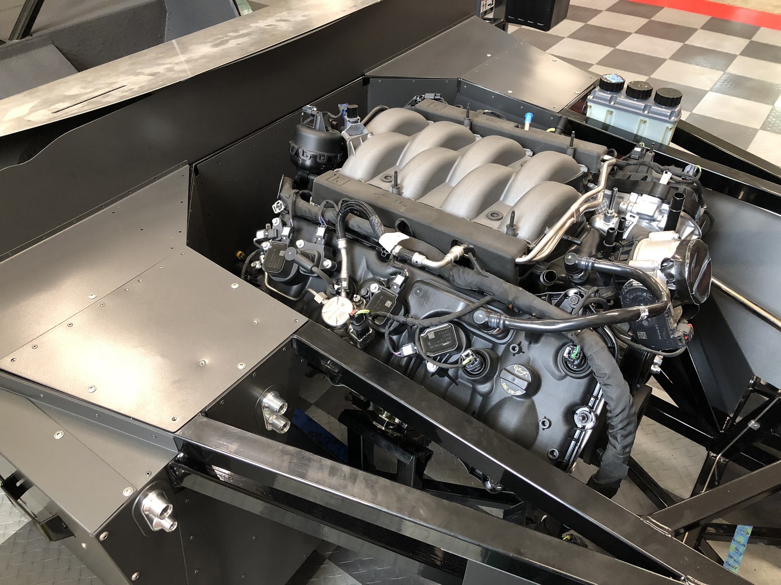
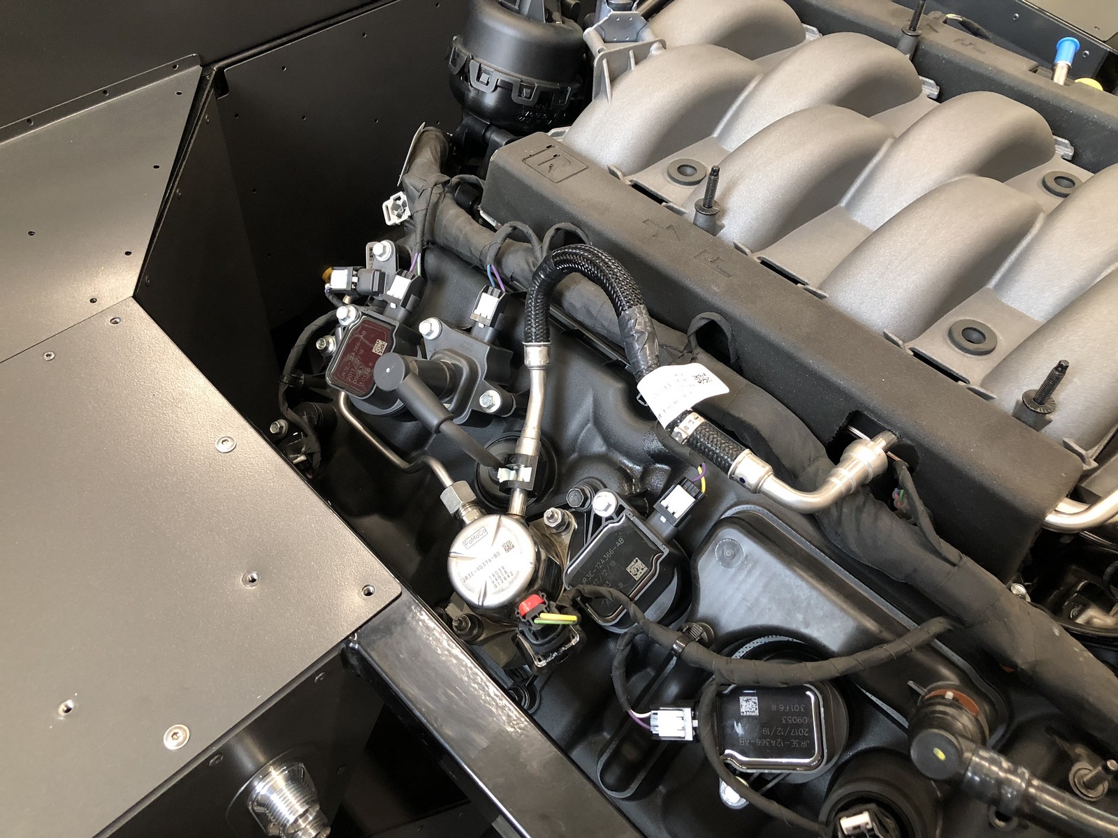
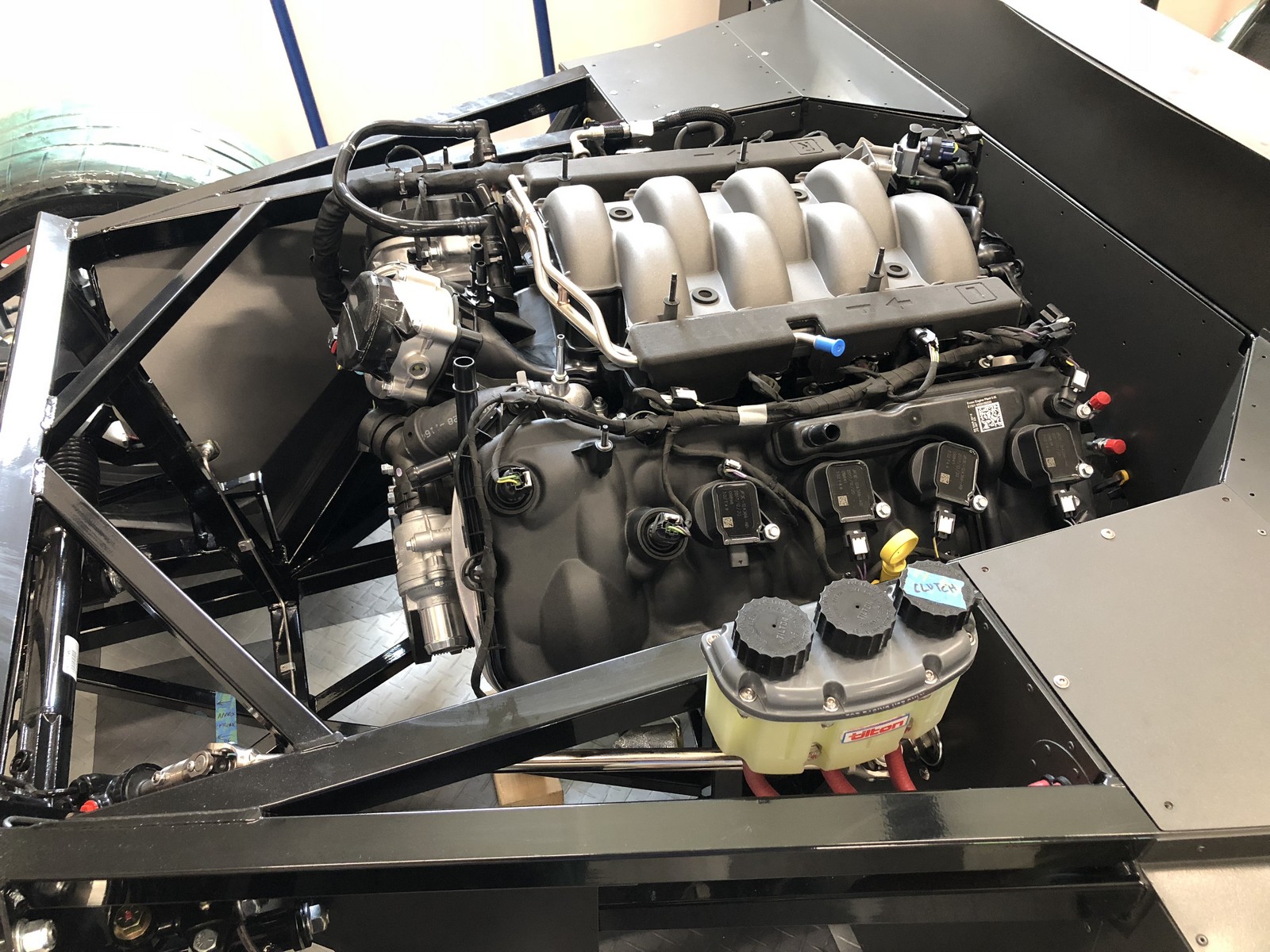
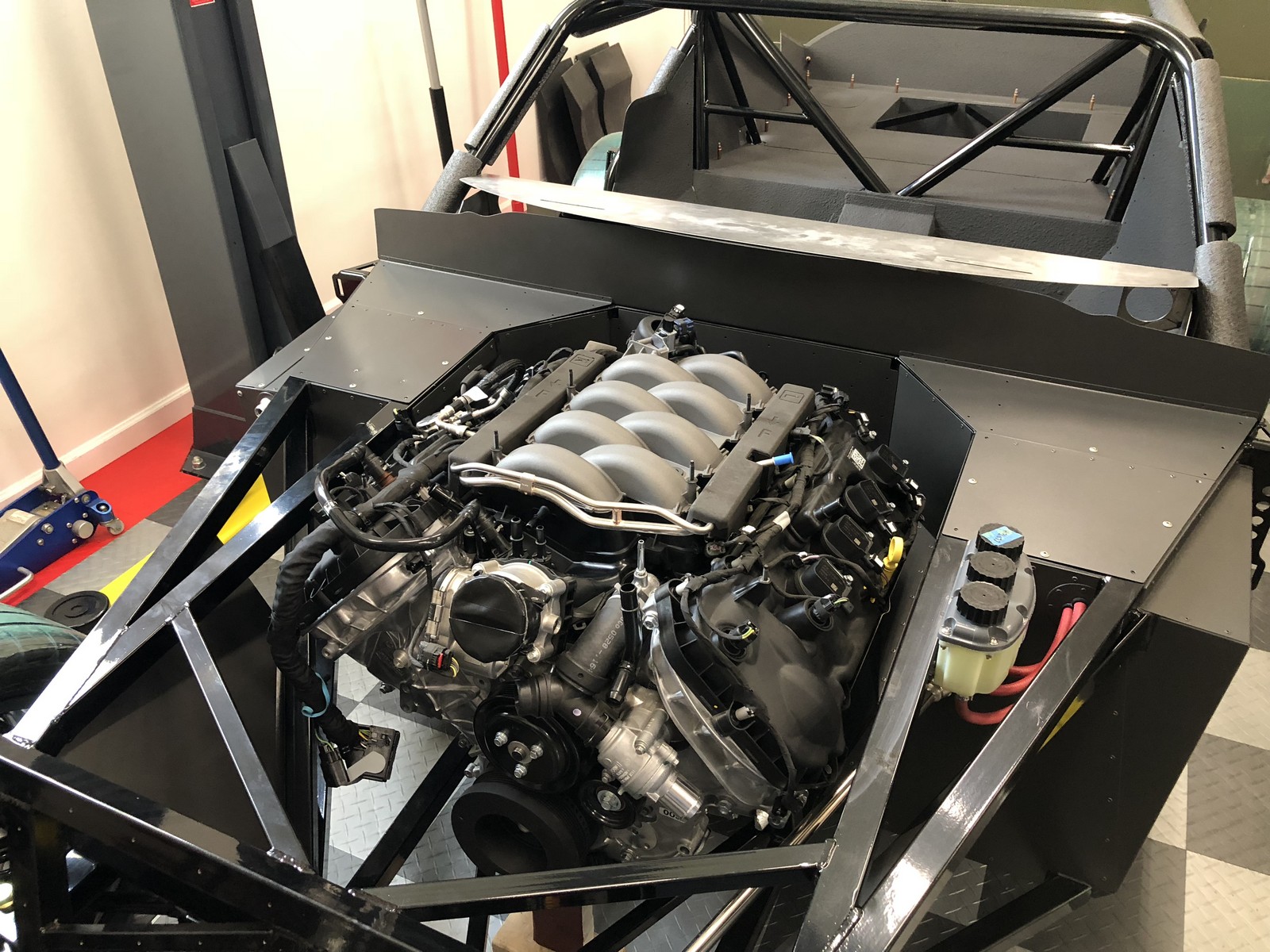
As can be seen in the pics, the tops of the heads are above the frame rails. Without the coil covers as the previous Coyotes, all the wiring and plumbing is hanging out for all to see. Don’t think much can be done about that. I don’t think the Gen 3 cover with the wings over that area would help at all. In fact, I’m thinking would look pretty out of place. Still an open subject. Probably will only try to do something over the intake itself.
Speaking of open subjects, here’s an update on the two issues I raised in my previous post:
Incompatible Moroso oil pan pickup due to the different oil pump in the Gen 3 Coyote: Heard back from Moroso. They are planning to offer an updated pickup. But no timing was offered. I asked for possible timing in a follow-up. At this point I’m not too optimistic that’s going to be a solution in time for this build. After staring at it for a while and thinking about it, I’m pretty confident I can modify the existing Moroso pickup with some tubing and my friend the welder down the street. Tearing the engine down and changed back to the former pump is absolutely not in the cards.
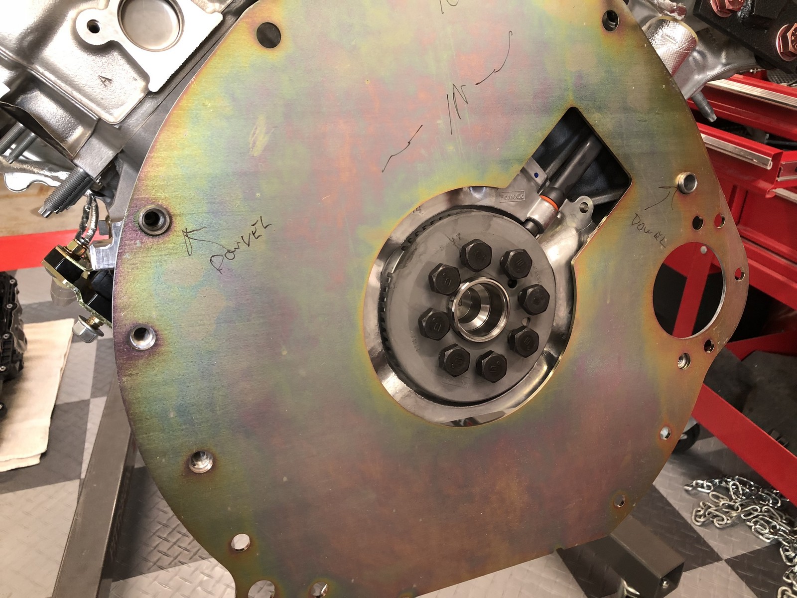
Incompatible dual mass flywheel: Today I removed the factory provided dual mass flywheel. Would have had to do that anyway to install the QuickTime block plate. Even if it would have worked with my bell housing and T-56 transmission. As best I can tell, the end of the crankshaft is unchanged from the previous version. Maybe even the same part. I’m confident a regular Coyote flywheel can be installed along with a standard clutch. Planning the same parts as used in #8674 as already mentioned. The only thing missing is the pilot bearing. The one in the dual mass flywheel is different. But that’s a standard part (M-7600-C) so will get one along with the other parts and all should be good. I temporarily mounted the block plate and bell and checked the dimension compared to the input shaft of the T-56. It’s perfect. So this is nearing resolution. This is what it looked like under the dual mass flywheel with my QuickTime block plate. I had already purchased new flywheel bolts.
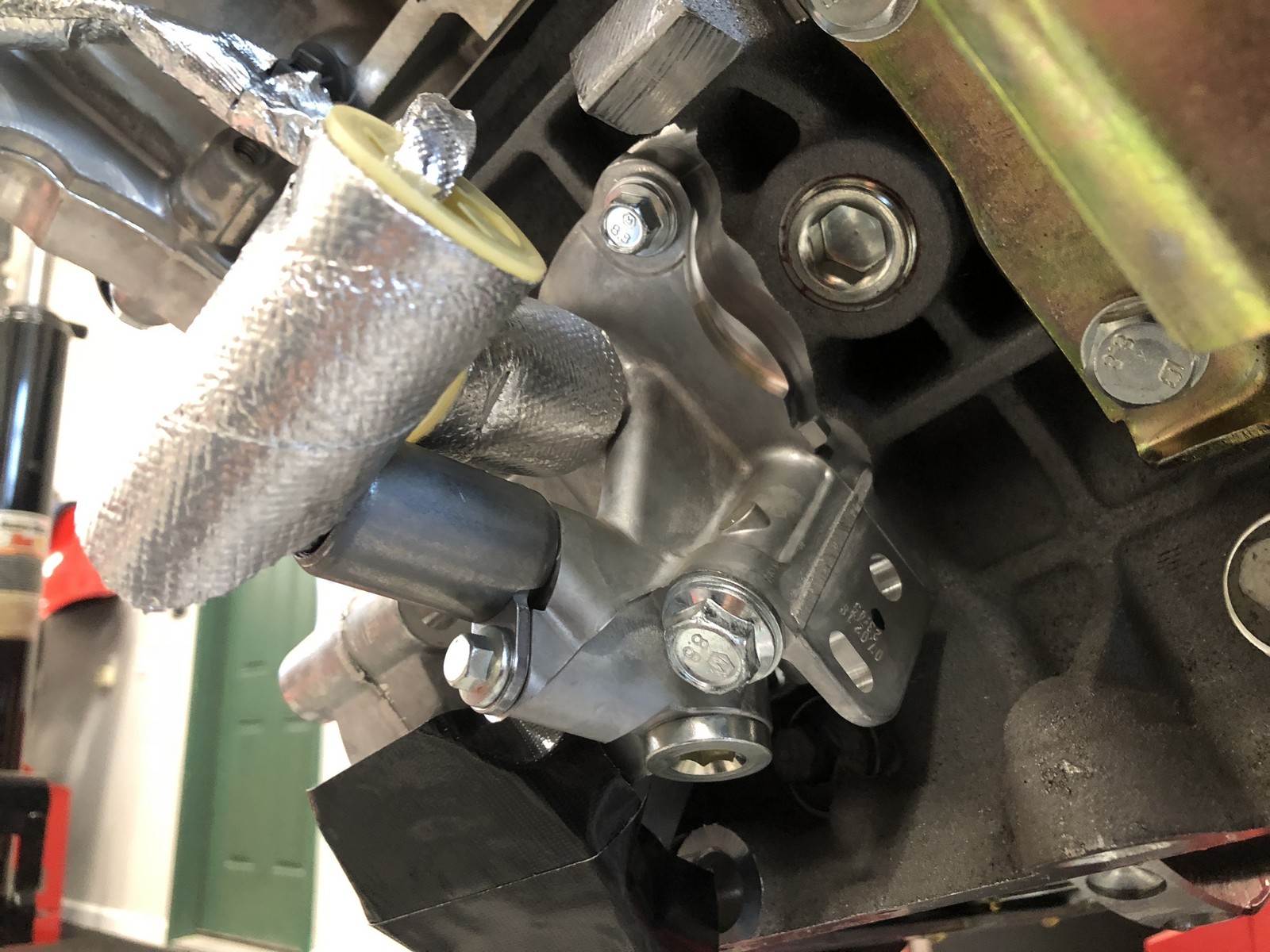
One other difference I noticed. There was another connection and device of some kind in addition to the oil pressure sensor. In the area of the oil filter. Removed the part and did a little digging. Turns out it’s an oil control valve, and appears to be used to route oil into the now removed oil cooler. Seems the F150 version of the Coyote has this valve, and now it’s on the Mustang version as well. Even though it’s not doing anything, I’m going to leave it in place just in case the PCM is expecting it to be there. Same for the oil pressure sensor. For later versions of the Gen 2, instructions were to remove the stock sensor and replace with the required unit for the dash gauge. Apparently the PCM wasn’t using this signal. I don’t know if the Gen 3 is the same, and at this stage might not be able to get a good answer. Simple solution is to leave it and T in the added sensor. Also note the little heat shields around the sensors. Several of those on the engine.
Update March 2020: The Gen 3 Coyote requires the OE oil pressure sender to remain. So a T fitting is required to add the gauge sender. Discussed later in the build thread.
Still a long ways to go. But feel a lot better about this than I did at this time yesterday.
Last edited by edwardb; 04-02-2020 at 08:59 AM.
Build 1: Mk3 Roadster #5125. Sold 11/08/2014.
Build 2: Mk4 Roadster #7750. Sold 04/10/2017.
Build Thread
Build 3: Mk4 Roadster 20th Anniversary #8674. Sold 09/07/2020.
Build Thread and
Video.
Build 4: Gen 3 Type 65 Coupe #59. Gen 3 Coyote. Legal 03/04/2020.
Build Thread and
Video
Build 5: 35 Hot Rod Truck #138. LS3 and 4L65E auto. Rcvd 01/05/2021. Legal 04/20/2023.
Build Thread. Sold 11/9/2023.
-
Senior Member

I know you have to be happy to finally have that bad boy in the garage, hopefully you can get the parts compatibility figured out without too much pain/cost. Have you contacted FFR to see if/when they are looking at Gen 3 compatibility?
-
Senior Member
Originally Posted by
Matt K.
Paul - is that a plastic pickup tube on the factory pan? Wow. Four-bolt mains next to a plastic pick-up tube. I wonder if that's standard practice in the automotive industry these days?
Yes, that's a plastic pick-up. Attached to the plastic oil pan. I can't say how common it is. Don't usually buy a new engine and then take it apart. ") These things undergo significant long term testing. So not too worried about it. But agree it's a little different. BTW, not just 4-bolt mains in the Coyote. Also side bolts through the block into the bearing caps. Pretty stout.
These things undergo significant long term testing. So not too worried about it. But agree it's a little different. BTW, not just 4-bolt mains in the Coyote. Also side bolts through the block into the bearing caps. Pretty stout.
Originally Posted by
shark92651
I know you have to be happy to finally have that bad boy in the garage, hopefully you can get the parts compatibility figured out without too much pain/cost. Have you contacted FFR to see if/when they are looking at Gen 3 compatibility?
Factory Five does have a Gen 3 in house. But no control pack. So they haven't started looking at it yet.
Last edited by edwardb; 08-30-2018 at 06:34 PM.
Build 1: Mk3 Roadster #5125. Sold 11/08/2014.
Build 2: Mk4 Roadster #7750. Sold 04/10/2017.
Build Thread
Build 3: Mk4 Roadster 20th Anniversary #8674. Sold 09/07/2020.
Build Thread and
Video.
Build 4: Gen 3 Type 65 Coupe #59. Gen 3 Coyote. Legal 03/04/2020.
Build Thread and
Video
Build 5: 35 Hot Rod Truck #138. LS3 and 4L65E auto. Rcvd 01/05/2021. Legal 04/20/2023.
Build Thread. Sold 11/9/2023.
-
Senior Member
Here we go with wiring and the rest
Spent some time today dragging parts out of the basement that had been mocked up before and started putting them where they’ll eventually stay. This is where the “One bite at a time…” saying has to be followed. There’s a lot to do but just go one step at a time. I’m feeling relieved I decided to drop the engine in for this stage. It’s tight plus a lot going on. I never would have been able to envision it (or get it right…) without that big chunk in there. Here’s what I’ve learned so far.
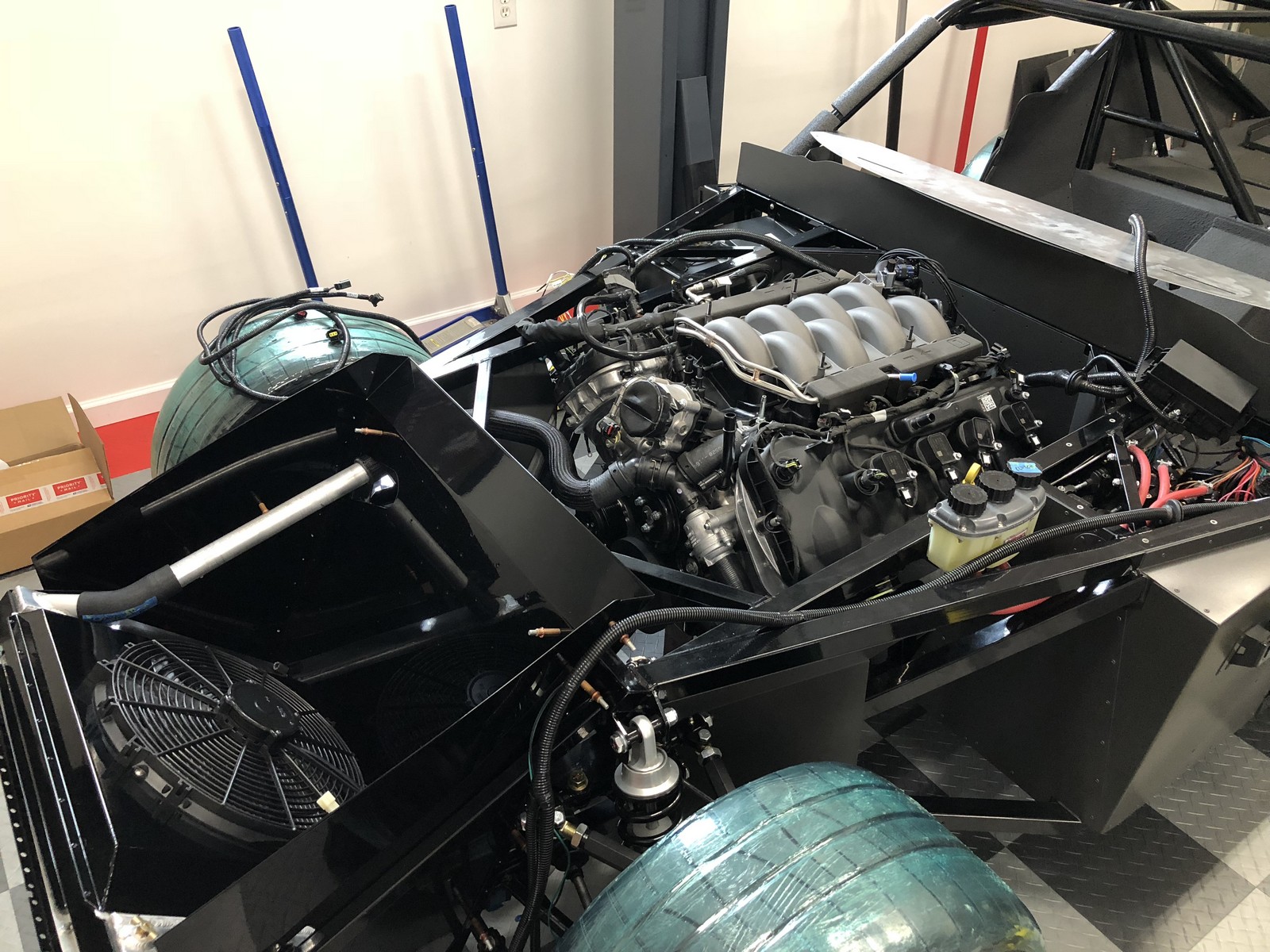
Mounted the radiator sheet metal and radiator/condenser. It will be coming off one more time to put the engine in permanently. But I wanted to check out the cool tubes from Boig now that I have the engine locations to aim at. Plus the routing of the upper and lower radiator hoses affects other things. Great news. Both of the Boig tubes fit perfectly! Bob promised they would, and he was right. I was mostly worried about that tiny window to get the lower hose through by the frame and sway bar. But it fits and the alignment to the engine is great. The upper hose also works out well with the cool tube and the control pack provided upper hose. The routing is excellent. Note I’m not using a T-filler since I’m using the Moroso Mustang pressure tank and Mustang hose routing. Same as #8674. Looks like the tank is going to fit in the center under the two cross pieces. Then the cold air intake will fit over into the opening on the DS. Similar to how it’s done in the Roadster.
Draped the various wiring harnesses into their preliminary locations, including the main RF harness, the front RF harness, and the main Coyote harness + PDB. Tentatively I’m planning to put the PDB on the firewall above the DS footbox. Then route the main cable behind the firewall and break into the engine compartment by the PS footbox. That will keep the majority of the cable hidden plus take up a little of the slack. I put enough of the heat and A/C components in to see where they’ll be and have to avoid. I see no choice but to put the Coyote PCM on the PS side above the header area. Very similar to where it's typically installed in a Roadster, as I mentioned before. Will have to get creative with some type of mounting bracket.

These pictures are just overall of what it looks like now and what I have to get buttoned down. Wiring and related doesn't bother me. Actually kind of enjoy it. But it's easy to see why some get intimidated at this stage. It should look quite different when done.

One final comment about a prior subject. The dual mass flywheel that came with the Gen 3 Coyote. As already stated, I’m not going to be able to use it. Ford did make some changes to the MT-82 6-speed for 2018 that’s used in the Mustang to address some issues and make it better. Obviously at the same time they must have shortened the input to match this setup. Perhaps that new MT-82 will be an option some may want to consider for their Gen 3 Coyote builds. Just for grins though I put the now loose dual mass flywheel on a scale. That bad boy weighs 34 pounds. The previous Coyote’s nodular flywheel I measured at 29 pounds. The Ford Performance M-6375-M50 billet steel flywheel I have in #8674 and will now use for this build weighs 20 pounds. I’m not a fan of the real light aluminum flywheels for street drivers. But going the other direction to 34 pounds seems really heavy. I probably would have still used it if it fit. But not sure it’s the best for these builds. Comments from someone who knows more about this than me? (Wouldn’t take too much.)
We have a busy couple weeks coming up, including some time away. So this will probably be the last update for a bit. Plus I have a lot to do to make a dent.
Last edited by edwardb; 09-01-2018 at 04:08 PM.
Build 1: Mk3 Roadster #5125. Sold 11/08/2014.
Build 2: Mk4 Roadster #7750. Sold 04/10/2017.
Build Thread
Build 3: Mk4 Roadster 20th Anniversary #8674. Sold 09/07/2020.
Build Thread and
Video.
Build 4: Gen 3 Type 65 Coupe #59. Gen 3 Coyote. Legal 03/04/2020.
Build Thread and
Video
Build 5: 35 Hot Rod Truck #138. LS3 and 4L65E auto. Rcvd 01/05/2021. Legal 04/20/2023.
Build Thread. Sold 11/9/2023.
-
Post Thanks / Like - 0 Thanks, 1 Likes
-
following this and your previous roadster build it looks like you need to install / remove the engine several times to get everything fitted properly. how many time do you typically need to install and remove? I assume these are all without the transmission until the final install? thanks for your input
-
Senior Member
Originally Posted by
kehenline
following this and your previous roadster build it looks like you need to install / remove the engine several times to get everything fitted properly. how many time do you typically need to install and remove? I assume these are all without the transmission until the final install? thanks for your input
I really can't say what's typical here. The #8674 20th Anniversary build was an early Gen 2 Coyote. Now the Coupe with an early Gen 3 Coyote. Both before they were being widely used or had instructions updated for these versions or other builders I could learn from. There are some similarities in all Coyote builds. But each version brings a couple of new wrinkles. Plus, in the case of #8674, was my first attempt at installing any Coyote. So for both builds it made sense to me and my build style to put the engine in before alot was finalized. Then determine wire routing, components mounting, etc. from there. In both cases, I chose to do engine only (e.g. less bell housing, trans, etc.) mainly because I'm by myself and that's something I can do by myself. Putting the complete engine in isn't hard and frankly would be better. But takes a couple more people to lift, push, pull, etc. Have friends I can call on for that, but try to keep it to only once. The SBF builds before these the engine went in once and that was it.
So bottom line, do what you're comfortable with and helps you think and work through the build. It's not particularly unusual for guys to take the engine in/out several times during the build. Also not unusual for it to go in once and be done. But the other comment I'd make is it's not hard to take the engine in and out. Especially before the body is on. In the case of the Coupe, without the front cowl. With the proper lift (I use a 2-ton HF shop crane) and the proper preparation, they go in/out in an hour or less.
Last edited by edwardb; 09-10-2018 at 03:47 PM.
Build 1: Mk3 Roadster #5125. Sold 11/08/2014.
Build 2: Mk4 Roadster #7750. Sold 04/10/2017.
Build Thread
Build 3: Mk4 Roadster 20th Anniversary #8674. Sold 09/07/2020.
Build Thread and
Video.
Build 4: Gen 3 Type 65 Coupe #59. Gen 3 Coyote. Legal 03/04/2020.
Build Thread and
Video
Build 5: 35 Hot Rod Truck #138. LS3 and 4L65E auto. Rcvd 01/05/2021. Legal 04/20/2023.
Build Thread. Sold 11/9/2023.
-
thanks, paul. that make sense. for a first timer like me, it wouldn't be hard to forge ahead without ever putting the engine in and then finding that something has to be redone because it is in the way of the engine. your experience is so valuable to this forum.
-
Post Thanks / Like - 1 Thanks, 1 Likes
-
Senior Member
Gen 3 Coyote Installation Update
Was away for several days visiting family. But back home to work, plan, and spend money. Making some progress. Still a long way to go, but here’s where I’m at today.
Dual-mass flywheel: Removed because it won’t work for me, as described before, and have received the following parts, all from Ford Performance:
- M-6375-M50 Lightweight Billet 8 Bolt Flywheel
- M-7600-C Roller Pilot Bearing - High Load - 4.6L/5.4L/5.0L4
- M-7560-T46 Clutch Assembly 26 spline, 11.0 inches (Note: Centerforce dual friction with Ford branding. Nice clutch.)
- M-6397-B46 Pressure Plate Bolts and Dowels
- M-6379-C Flywheel Bolts
I don’t have everything assembled yet, and won’t until the engine is back out. But I’ve checked and measured everything and all appears to fit perfectly. Note as I mentioned before, this is the exact setup I have in #8674. So this just appears to confirm nothing has changed at this end of the Coyote once that dual-mass flywheel is removed. I mentioned before the 2018 Gen 3 Coyote also uses a twin disk clutch. Just to be clear, that doesn’t come with the crate motor. The previous Coyote crates didn’t include a clutch either. So no change there. The only difference in the shopping list above compared to previous Coyote versions is the pilot bearing and the flywheel. Previous versions already had a pilot bearing in the end of the crankshaft. Now you have to add it. Previous versions had a nodular flywheel which many used. I did choose to upgrade to the lighter billet steel version listed above for #8674. So for me wasn’t a difference there. I’ll know for sure when it’s time to assemble all of the above, but I’m 99% confident this issue is resolved.
Moroso oil pickup tube: I heard back from Moroso a second time. First time they confirmed they knew their pickup tube wasn’t compatible with the Gen 3 Coyote. Said they would have an updated part sometime. I followed up asking “When?” and the answer was "TBD. No schedule at this time." So this will hopefully be a solution for other builders. But I’m not optimistic it will be for me. My plan now is to modify the existing pickup. I’ve just ordered a couple pieces of tubing from McMaster. I’m going to use the composite oil pan with the new style connection to make a fixture and cut/weld the old style Moroso pickup to fit the new pump and the Moroso low profile pan. I’m confident this will work fine. Will provide updates when completed.
Since the last update, received the Ford Performance M-8600-M50BALT 5.0 Alternator Kit, same as used on previous Coyotes. It fits fine. Also since the last update, have determined the location and method for mounting the PCM. I’m going to make a bracket that sandwiches it against the chassis tube in the location pictured previously. Will provide updates when completed. I’ve started the modification to the DBW module (accelerator pedal) and am using some ideas from another builder to re-use the existing pedal rather than the FFR supplied pedal piece. Looks like it’s going to work well. I’ll finalize that later when I have easier access to the footbox. One surprise (disappointment…) is that FFR put a nice mounting plate in the footbox that exactly matches the mounting screws on the Coyote DBW. Clearly they’re expecting lots of people to use a Coyote and DBW module. Unfortunately, it’s about 1/2-inch too high. Mounted in the holes provided, the connector for the DBW runs into the steering column. Easy enough fix to drill new holes. But missed it by that much… I've also decided to go with an Odyssey battery. The stock location is in the front, but height is somewhat limited by the steering rack. The Odyssey PC925T fits nicely. Same one recommended for the Hot Rod, and recommended by lots of builders. Small and relatively light.
New issues/findings: The throttle body on the Gen 3 Coyote appears to be another change. The inlet is the same diameter. But it’s angled UP 8-9 degrees more than the previous Coyotes. So some care is needed to use a right angle connector that turns down quickly because the underside of the cowl is already pretty close to the throttle body. The FFR listed Spectre parts, which I have in #8674, don’t look like they will fit. Both because of that and also because of the chassis bar in front of the engine. I’ve looked at a number of other aftermarket cold air intakes (Rousch, JLT, BBK, etc.) and doesn’t look like they’ll fit either. Granted one of my issues is I’m also trying to install the Moroso radiator pressure tank. So have to work around that too. After some research and lots of measuring, have ordered some parts from Treadstone Performance that I think (hope) will work. They just shipped so don’t have an update yet. But will when received and checked out.
Next finding, and last one for this update, is the famous Gen 3 Coyote engine cover. I went ahead and ordered one with the other parts listed above. Popped it on last night. First impressions are that it doesn’t look “too bad.” (Be nice when you see it. Remember what your Mother taught you. If you can't say anything nice...) But looks like the front outside corners of the “wings” hit the underside of the front cowl. Right now I’m just mocking up the location of the front cowl as best I can, so it’s possible it might barely fit when the cowl is actually installed. But it’s really close. The wings also really don’t do too much to cover up the wiring and tubing on the top of the heads. So my tentative plan for now is that I’m going to cut the wings off. I actually think it will look decent at that point. I do like the cleaner lines and sharper styling of the new cover compared to previous versions. With it cut off (I added lines in the picture below to show where I’m thinking to trim it) it will cover up some things and I think look OK. Probably will get some kind of custom painting on it like #8674. Without the wings, I also think it will clear the underside of the cowl. I’m not going to do anything with the cover for now. Will wait until I’m further along to cut and finish. But that’s the initial idea/impression. And just in case someone suggests changing the intake to something different (and better looking…) the Gen 3 stock intake is changed from previous versions and is getting great reviews in multiple tests. One of many changes making the Gen 3 closer to the GT350. Some are even using it as an upgrade to previous Gen Coyotes. So changing the intake isn’t going to happen for multiple reasons. Here are pictures. Onward and upward.


Last edited by edwardb; 09-13-2018 at 05:36 AM.
Reason: Typos and spelling
Build 1: Mk3 Roadster #5125. Sold 11/08/2014.
Build 2: Mk4 Roadster #7750. Sold 04/10/2017.
Build Thread
Build 3: Mk4 Roadster 20th Anniversary #8674. Sold 09/07/2020.
Build Thread and
Video.
Build 4: Gen 3 Type 65 Coupe #59. Gen 3 Coyote. Legal 03/04/2020.
Build Thread and
Video
Build 5: 35 Hot Rod Truck #138. LS3 and 4L65E auto. Rcvd 01/05/2021. Legal 04/20/2023.
Build Thread. Sold 11/9/2023.
-
in the first picture the cover looks like it really cleans up the look but then in the second picture well, not so much. I think you will need to see it with the body and hood in place to decide.
oh, and as always great pictures and information.
David W
Mkll 4874 built in 2004
Gen 3 coupe #16 registered 2018 painted 2019
-
Senior Member
Originally Posted by
David Williamson
in the first picture the cover looks like it really cleans up the look but then in the second picture well, not so much. I think you will need to see it with the body and hood in place to decide.
oh, and as always great pictures and information.
David W
Thanks. Yea I'm not sure how different it will look with the body and front cowl since the front tips up and exposes everything pretty much like the pictures show. But I agree. I put the unmodified cover back in the box and will decide when things are more finalized. Can validate the fit and what it looks like. What I did learn is that I will use at least some of it.
Build 1: Mk3 Roadster #5125. Sold 11/08/2014.
Build 2: Mk4 Roadster #7750. Sold 04/10/2017.
Build Thread
Build 3: Mk4 Roadster 20th Anniversary #8674. Sold 09/07/2020.
Build Thread and
Video.
Build 4: Gen 3 Type 65 Coupe #59. Gen 3 Coyote. Legal 03/04/2020.
Build Thread and
Video
Build 5: 35 Hot Rod Truck #138. LS3 and 4L65E auto. Rcvd 01/05/2021. Legal 04/20/2023.
Build Thread. Sold 11/9/2023.
-
Top Notch Builder
I’ve been slammed at work and just caught up with your thread and wow. Huge progress!
Id say make cardboard template. Paint it black and see how it looks before your cut into that plastic engine cover. I actually like it better without. I’m not offended by the wires. It’s growing on me actually. Also I like the look of the intake and it covers that up. Maybe even something fabricated from aluminum might look cool too if it doesn't cause interference. One other thought would be maybe a body matching color on an engine cover or shroud will bring some continuity into that area and draw attention to the cover and away from the wires if you don’t like the wires.
Working this stuff out is half the fun I’m sure. Enjoy!
Last edited by P100DHG; 09-15-2018 at 11:10 AM.
-
Post Thanks / Like - 1 Thanks, 0 Likes
-
Member

While I haven't officially mounted my computer yet I did a mock a couple months ago, after looking at my 2016 Mustang GT the computer is mounted just off the front corner of the passenger head, far enough forward from the exhaust and tuck in, that is general area where I'll be mounting my computer soon as thing cool off a bit , 107 in Phx today too hot right now.
-
Post Thanks / Like - 1 Thanks, 0 Likes
-
Senior Member
Originally Posted by
Paul G
While I haven't officially mounted my computer yet I did a mock a couple months ago, after looking at my 2016 Mustang GT the computer is mounted just off the front corner of the passenger head, far enough forward from the exhaust and tuck in, that is general area where I'll be mounting my computer soon as thing cool off a bit, 107 in Phx today too hot right now.
Agreed. Ford designed the harness on the engine for the PCM to be mounted in that general area. The 2018 is similar. Some guys take apart the harness so it can be re-routed and mount the PCM on/near the firewall. But I'm not going to try that. Not just because I don't want to break into the cable, but also because the firewall area (and behind) is also really crowded plus there'd be 4-5 feet of extra harness to deal with from the PDB. Yesterday I completed a mount for my PCM and will show some details in my next update. It ended up in a similar location between the frame rails as I showed in a previous update and picture. It's tight with everything else going on. But I think it will work.
Build 1: Mk3 Roadster #5125. Sold 11/08/2014.
Build 2: Mk4 Roadster #7750. Sold 04/10/2017.
Build Thread
Build 3: Mk4 Roadster 20th Anniversary #8674. Sold 09/07/2020.
Build Thread and
Video.
Build 4: Gen 3 Type 65 Coupe #59. Gen 3 Coyote. Legal 03/04/2020.
Build Thread and
Video
Build 5: 35 Hot Rod Truck #138. LS3 and 4L65E auto. Rcvd 01/05/2021. Legal 04/20/2023.
Build Thread. Sold 11/9/2023.
-
Senior Member
Another Gen 3 Coyote Install Update
Plugging away on details for the Gen 3 Coyote installation. Have basically determined how I’m going to deal with two major items: PCM mounting/cable routing and cold air intake.
PCM mounting: Some of this I’ve talked about before. The large harness and connector coming off the engine terminates near the front corner of the RH head. Without modifying the cable, really no choice but to put the PCM in that vicinity. I know some guys unwrap the cable and then mount the PCM in the firewall or PS footbox area. Thought briefly about that. But the harness is complex (wires exit along its path for each injector, coil pack, multiple sensors, and now the new DI hardware) and I just don’t want to dive into it. Plus it’s already congested in the firewall area and beyond with the A/C and heat, accessories I’ve added, etc. Plus I'd have a whole bunch of excess cable between the PCM and PDB to deal with. So I’m staying with mounting it near the RH front of the engine. Note this is nearly identical to the location used on #8674 and how FFR shows in their instructions for the Roadster. I know some are concerned about the headers in that area. But it hasn’t proven to be an issue. These modules are made for the harsh underhood environment. Within reason of course. Note also this is the same general area that Ford mounts them in the Mustang. What’s interesting though is in the Mustang it’s packed in with a lot of other stuff and doesn’t appear that it would have much airflow around it. As opposed to ours that are more free-standing. So seems to me it’s completely safe there.
So for the actual mounting, the new Bosch PCM with the Gen 3 only has two mounting ears near the connectors, versus the four the previous version has. Plus they’re not too friendly to attach to IMO. I decided to make a bracket that sandwiches the PCM and holds it suspended under the frame rail in the area mentioned. After some patterns, prototypes, and one fail, have finalized on a piece of 1-1/2 inch right angle aluminum riveted to the frame rail, and a wraparound bracket made from mild steel. I have nutserts in the aluminum bracket and will use 1/8 inch cushioning material where the PCM is contacted. Looks like this:


My first approach was to mount the PCM facing down, e.g. wire connections on the bottom. I thought it looked a little neater. Like this:

But after thinking about it a couple days and sitting and staring at it for awhile (that again…) decided that wasn’t such a good plan. The wiring was way too congested with everything else, no clear path for the large harness that needs to go back to the PDB, plus the connectors and wires would be the closest thing to the header area. So flipped it over and this is what I’m going with:

This will get cleaned up a bunch for the final installation. The large center connector is from the engine, obviously. The front connector goes to the PDB. That harness needs to be re-configured quite a bit. I’ll unwrap it and bring the starter and fan wires back to the PDB area. Probably also the engine connections (alternator, MAF, etc.). That will make the cable a little skinnier where it's visible FWIW. I’ll run the cable along the outside of the top frame rail, along the bottom of the firewall, and to the PDB near the center of the firewall. I was hoping to hide the cable a little more than that, but just not in the cards. There will be heater and A/C hoses all over the place in the same area. So I’m thinking it’s no big deal. The rear connector, BTW, is only for the O2 sensors. Ford changed how they’re wired again. So all three Gen Coyotes have been different. In this case, the wires go directly from here to the sensors. It too, though, will need to be reconfigured to be optimal. That’s as far as I’m going to go for now. When the engine mockup comes out, I’ll get everything mounted and wired for good.
Cold air intake: Some of this I mentioned before too. The throttle body on the Gen 3 Coyote points up 8-9 degrees more than before. Plus the cowl is relatively close on the underside. I looked at several of the Mustang aftermarket cold air intake kits, but didn't see one that would fit. The Spectre setup FFR has in their instructions and I have in #8674 won’t fit either. They do mention a MAF tube from Treadstone Performance. In looking at that piece plus other items on their website, came up with a combination that I hoped would fit. Received the parts today, and all is good. I’m impressed with the quality of the parts too. I’m especially pleased the MAF tube has rolled ends. So properly clamped they shouldn’t come apart. (Reference “Ride of Shame” thread for #8674…) The right angle coupler is very robust. I’ll need to add a connector for the PCV hose, but that’s easy enough. The parts I received are:
- S35090BLK 90 Degree Silicone Hose Coupler 3.50" - 3.50" (103411-128578) Black
- MAPHL35 MAF Mass Air Flow Adapter Pipe, 3.50" Low (103748-129055) Polished aluminum
- AF10044BLK Air Filter Medium 3.5" Neck (104214-129638) Black
Factory Five also sells this same Treadstone MAF tube. Their part number 16403. They also sell a 90deg Silicone Hose – FFR#16404, and Coyote Air Filter – FFR#16608. But I don't know if those two are the same has what I bought directly from Treadstone. I had to cut 1-inch off the right angle coupler where it plugs onto the throttle body. It was too long as I suspected from their pictures. With that, it fits up exactly like I hoped. Based on pictures and measurements taken previously, it will fit under the front cowl.


The cold air intake leaves just enough room for the Moroso cooling system expansion tank. It’s tight, but not quite as tight as the angle on this picture indicates.

On a related note, on the Treadstone Performance website they promoted the use of a honeycomb airflow straightener in the MAF tube. Installed at the neck of the tube on the air filter side to clean up the air going through the sensor. Did a little Google searching, and maybe has some merit. Supposedly improves MAF readings at lower RPM's. So added one to my order. Thinking I'll just keep it aside for the moment. But something I'll take a look at down the road. Next up is to make brackets for the Moroso expansion tank and finalize the Odyssey battery mount. Then the engine will come back out.
Last edited by edwardb; 09-18-2018 at 03:12 PM.
Build 1: Mk3 Roadster #5125. Sold 11/08/2014.
Build 2: Mk4 Roadster #7750. Sold 04/10/2017.
Build Thread
Build 3: Mk4 Roadster 20th Anniversary #8674. Sold 09/07/2020.
Build Thread and
Video.
Build 4: Gen 3 Type 65 Coupe #59. Gen 3 Coyote. Legal 03/04/2020.
Build Thread and
Video
Build 5: 35 Hot Rod Truck #138. LS3 and 4L65E auto. Rcvd 01/05/2021. Legal 04/20/2023.
Build Thread. Sold 11/9/2023.
-
Post #407
Quick note on the honeycomb for the air flow, for those that want to go deeper on the subject, look up diy laminar flow fountains. They use drinking straws to smooth the flow of water, similar to the honeycomb for air ! Does it help with the MAF? I have no clue
Mk3.1 347 AFR 205cc Heads A9L EFI siemens deca 60lb injectors MSD 6AL ignition Vortech V-3 3 Link PS/PB
-- If you cant fix it with a hammer, you have an electrical problem !
-
I had initially mounted my Moroso tank on the angle frame at the front DS. It is solid with nice bracket fab, but I don't like how it looks at an angle. Now I am reconfiguring and see that I can squeeze it in where you propose yours. I am completely racking my brain on how to build a bracket. Lots of angles and a fair moment on the tank mounting tab due to the weight of the full recovery tank. I am interested to see what you come up with. Also, I am going to try an F150 upper radiator hose. I am thinking it will take the turns better. Just curious. WHat is your battery plan. Is that brake line(to front PS) going to be in your way?
Last edited by jdavis500; 09-21-2018 at 10:52 AM.
-
Senior Member
Originally Posted by
jdavis500
I had initially mounted my Moroso tank on the angle frame at the front DS. It is solid with nice bracket fab, but I don't like how it looks at an angle. Now I am reconfiguring and see that I can squeeze it in where you propose yours. I am completely racking my brain on how to build a bracket. Lots of angles and a fair moment on the tank mounting tab due to the weight of the full recovery tank. I am interested to see what you come up with. Also, I am going to try an F150 upper radiator hose. I am thinking it will take the turns better. Just curious. WHat is your battery plan. Is that brake line(to front PS) going to be in your way?
Just finishing up the bracket I came up with for the Moroso tank. You're right, lots of angles and an interesting challenge. I'm sure there are multiple ways it could be done. But I'll show what I came up with in the next couple days. The upper radiator hose I'm showing here is what came with the 2018 control pack and it snakes around the tank location perfectly. That was lucky. I'm also working on my battery mount today. I'm using a smaller Odyssey battery and a mount made for it. It fits in the same general area as Factory Five shows for the stock mounting. The brake line isn't an issue. The battery will be forward of where that crosses. I'll have pictures of that in the next couple of days as well.
Build 1: Mk3 Roadster #5125. Sold 11/08/2014.
Build 2: Mk4 Roadster #7750. Sold 04/10/2017.
Build Thread
Build 3: Mk4 Roadster 20th Anniversary #8674. Sold 09/07/2020.
Build Thread and
Video.
Build 4: Gen 3 Type 65 Coupe #59. Gen 3 Coyote. Legal 03/04/2020.
Build Thread and
Video
Build 5: 35 Hot Rod Truck #138. LS3 and 4L65E auto. Rcvd 01/05/2021. Legal 04/20/2023.
Build Thread. Sold 11/9/2023.
-
Senior Member
Engine Mockup, Battery, Moroso Tank
Today I finished everything I wanted to do planning wire and hose routing, accessory mounting, etc. So lifted the engine back out of the engine bay and onto the stand for now. Easy enough to do without a bell housing and transmission in the way. Put the chassis back on the lift. Good to have it back there. Man I am definitely spoiled. First thing I did once I had it out was install the M-7600-C pilot bearing and check the fit of the M-7560-T46 flywheel. Everything fits fine so that little issue is completely closed as far as I’m concerned. I had the pilot bearing in the freezer and it drove right in using a 1-inch socket around the perimeter. Also had the clutch dowels in the freezer so drove those into the flywheel. Tomorrow I’m going to put the accessories on the engine (alternator, A/C pump, KRC power steering) and then start working on the modification to the Moroso oil pan pickup.


Here is a picture of the Odyssey PC925T battery I’m using. Relatively small and easily fits in this location. Listed as 28 lbs, but I haven’t weighed it. Since it’s AGM, I can use the same CTEK 3300 charger I’ve been using for the Optima in #8674. After looking at a number of choices, including the kit provided battery tray, decided to go with this Artec Industries OY9251 battery mount. Had to drill new holes in the base because the ones they had didn’t line up with the frame. But that was easy. Held in place with four heavy duty 1/4-inch nutserts. I’ll have it powder coated before final installation.

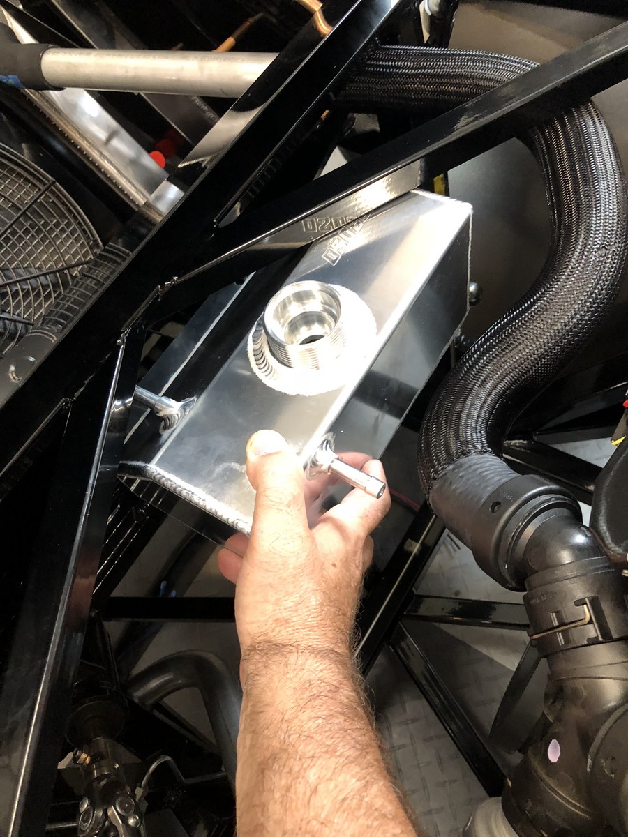
Also finished the mounting bracket for the Moroso radiator expansion tank. After thinking through several approaches, this is what I went with. The mounting location isn’t real handy, so took some unusual shapes and angles to get it done. The main mount is .090 aluminum, and the braces are .052 aluminum with a 1/2-thick aluminum piece between. My little H-F brake won’t touch these thicknesses, so bent all the pieces in my bench vise using angle iron and a wood block and hammer. Kind of dings the aluminum up a bit. But will be completely hidden plus powder coated. There are two 5/16-inch nutserts for the flange mount on the tank, and then the bottom piece fits into the receptacle on the bottom of the tank along with a piece of cut heater hose for a cushion. Now that I have the engine out, I can reach the mounting location and will install with three heavy duty 5/16-inch nutserts. Same kind as shown on the mount itself. Just with the clamps, it’s rock sold so I’m confident it will be OK.


So last night as I was wrapping up this mount, I realized how much lower it is than the same tank in #8674. Not sure how or why I didn't see this before. Further checking shows the top of the tank is basically even with the “T” connection on the LH side of the engine where the hose out the bottom of the tank is connected. Visible in the last picture above with the black cap. Since this is the intended fill path for coolant through the cap on the expansion tank, and fluid isn't going to go uphill any further than the level in the tank (at least when gravity is the only motivation) decided I might have a problem. My first inclination was to go back to the drawing board. Ugh. But with the time and money invested in this setup so far, not giving up so easily. With the available space, the frame design including the large angle braces across the opening, and everything else that needs to fit into this same real estate, there’s no easy option that I can see that would raise this tank any higher.
Did a whole bunch of searching, both in the forums and otherwise, and thought it about it a bunch. Here’s my conclusion: The only real problem will be the initial coolant fill and subsequent flush/re-fills down the road. The heater hose connection just above the “T” where the hose from the tank attaches (also visible in the last picture above), can be removed and coolant filled there with a funnel or whatever. Although not ideal, since it happens pretty rarely, not a big deal. Once the system is full and sealed and under pressure, the expansion tank will still do what it’s intended to do. It will still burp the cooling system from the connection on top of the engine and top of the radiator. It will still accept excess coolant as it heats and expands, and will be drawn back into the system as it cools. In that regard, no different than a standard overflow tank that is often mounted quite low in the engine compartment. I thought about installing the kit provided T-filler in the upper radiator hose and use that for filling. But that adds two more joints in the hose plus the cap. I can live with using the heater hose connection.
I contacted the Ford Performance help desk to see what their take was and if they thought my thinking made sense. Not much help to be honest. Response was “mount the tank as high as you can,” “mount it the same height as the engine,” (asked what part of the engine, but no answer), and “mount it higher than the tanks on the radiator.” It is. That’s not an issue. Because of the forward location and angle of the radiator, the side tanks are well below the expansion tank. That was all I got. No stoppers. But no firm endorsement of my plan either.
Bottom line, even though the expansion tank is lower than ideal and will take a little special handing for the initial fill, I don’t see it working any differently than the FFR supplied T-filler and overflow tank. Actually it’s better because it has the provision for burping via the engine and radiator connections. Anyone have any thoughts about this and reasons why I shouldn’t go ahead with mounting the Moroso tank where pictured?
Last edited by edwardb; 09-24-2018 at 10:27 PM.
Build 1: Mk3 Roadster #5125. Sold 11/08/2014.
Build 2: Mk4 Roadster #7750. Sold 04/10/2017.
Build Thread
Build 3: Mk4 Roadster 20th Anniversary #8674. Sold 09/07/2020.
Build Thread and
Video.
Build 4: Gen 3 Type 65 Coupe #59. Gen 3 Coyote. Legal 03/04/2020.
Build Thread and
Video
Build 5: 35 Hot Rod Truck #138. LS3 and 4L65E auto. Rcvd 01/05/2021. Legal 04/20/2023.
Build Thread. Sold 11/9/2023.
-
kind of like a chess match - have to think a few moves ahead as you figure out where everything goes. All part of the fun with the build.
as I have said many times "if it was easy everyone would have one"
David W
Mkll 4874 built in 2004
Gen 3 coupe #16 registered 2018 painted 2019
-
Senior Member
Impressive mounting bracket, especially for vise bending!
-
Is the expansion tank pressurized? and if it is just connected to the cooling system with a hose it needs to be high up. But if you have a rad cap on the upper rad hose and have a non-presurized recovery tank it can be lower. The vacuum in the cooling system will pull the coolant up from the tank.
David W
Mkll 4874 built in 2004
Gen 3 coupe #16 registered 2018 painted 2019


 Thanks:
  Likes:


 Reply With Quote


