-
Senior Member

A Kennebunk Build: It's Legal!! plus many other updates, like moving to Michigan
Hello All! I started an introduction thread in the general roadster section, but now that it's official, I'm kicking off my build thread.
Here's the plan:
Complete Kit
IRS
Coyote/TKX
Hydraulic Clutch
Power Steering
13" rear brakes
Powerstop front brakes
Wipers
Forgestar F14 satin black wheels 18x9, 18x11
I was unsure what to do about seats, but was pleasantly surprised with the quality of the vinyl seats. With that, I'm planning on rapper extreme for the dash to match the texture.
Living in Southern Maine, I made the trip to Wareham to pick up the kit. Everything BARELY fit in the Yukon and in the car. The pumpkin helped hold the windshield and gas tank in place for the trip back! If you haven't made it, absolutely worth the trip. Great people and great motivation every time I go and sit in the showcars.
https://thefactoryfiveforum.com/asse...2&d=1659009656
https://thefactoryfiveforum.com/asse...2&d=1659009329
I completed the inventory this week and sent off my list of shortages. When i picked up my car, they said I was one of the first people to go through the "NEW" inventory sheet process. I have no comparison, as this is my first car. The inventory was pretty painless. Other than a couple nuts/bolts/washers, all was accounted for per the inventory by FF and the POL list. Only issue was I didn't receive 2 boxes of IRS parts and received an extra box of front spindles. Credit to FF, they're all over it and addressing the discrepancies.
Funny inventory story. So FF says this inventory process is much smoother than the last. I start with box #1. Item #1 on the page - 1/2 rollbar box. I look all over and cannot find 1/2 a rollbar. My confidence is a bit shaken given that i can't even find item 1 in box 1. quick email to FF clarified that 1/2 rollbar box is actually the box itself that it came in. ha! oh well!
With inventory complete, I removed the body and will start drilling some panels to get to powder coat. THIS IS AWESOME!!!
-
Post Thanks / Like - 0 Thanks, 2 Likes
-
Senior Member
OK, still working on photo inserting...
-
Senior Member

Congrats and welcome, Mike. I went back to your thread on the main forum just to see your 'hello' note ... looks like you've done plenty of reading and prep so you know what you're in for. I too have been new to every stage of the build, and while learning and doing things for the first time on your own build has its moments of frustration, its really a rewarding process overall. For what its worth in relation to your questions on brake lines and other items, I used the steel brake lines that came with the kit, figuring they're coated and not going to be very challenged by summer driving and winter storage in MN. But NiCop is a great choice and I could have easily one that route. I took the side pipes as part of the complete kit but they'll only get used for first start and go kart, unless my GasN pipes get here in time for that. I have the stock seats that came with the kit for now, but I too am constantly puzzling through alternatives, and at some point I'll try one out.
For me the most (and most rewarding) learning has been around how to fab metal vs. wood, which I had much more experience with. Its amazing how much you can get done with a few hand tools, plus a few key adds, plus some technique / practice.
Super exciting to actually have the kit in house - have fun. And good choice to do a build thread. You get free expert oversight and helpful commentary in case you've got anything wrong in your build. Cheers, John
MK4 #7838: IRS 3.55 TrueTrac T5z Dart 347
The drawing is from ~7th grade, mid-1970s
Meandering, leisurely build thread is
here
-
Senior Member
A Kennebunk build: where is the clutch switch?
Working on the pedal box, and I found the two switches for the pedals themselves. I cannot find the switch that goes to the left of the clutch - the one that is depressed when the clutch pedal is engaged. Any idea which box that is found in? I searched the inventory sheets and cannot find it.
Side note, Ive also found some discrepancies with the new inventory process. For example, there is no steering wheel listed on any inventory sheet. That one is fairly obvious, as I cant sit in the seat and make VROOM VROOM noises. It could be that the clutch switch is another victim of the new inventory process growing pains
.
-
Senior Member


Originally Posted by
mmklaxer

Working on the pedal box, and I found the two switches for the pedals themselves. I cannot find the switch that goes to the left of the clutch - the one that is depressed when the clutch pedal is engaged. Any idea which box that is found in? I searched the inventory sheets and cannot find it.
Side note, I’ve also found some discrepancies with the new inventory process. For example, there is no steering wheel listed on any inventory sheet. That one is fairly obvious, as I can’t sit in the seat and make VROOM VROOM noises. It could be that the clutch switch is another victim of the new inventory process growing pains….
not sure what you mean...what do the 2 switches look like? they should be the same; black body w/ white plunger. One is your brake switch and the other is your clutch safetly switch. FYI, unless the manual has been updated, it shows the wrong wiring for the clutch switch. Needs to be reversed. I found this out when I noticed that I could start my car w/o the clutch depressed and couldn't start it when the clutch was depressed.
-
Senior Member
Originally Posted by
egchewy79
not sure what you mean...what do the 2 switches look like? they should be the same; black body w/ white plunger. One is your brake switch and the other is your clutch safetly switch. FYI, unless the manual has been updated, it shows the wrong wiring for the clutch switch. Needs to be reversed. I found this out when I noticed that I could start my car w/o the clutch depressed and couldn't start it when the clutch was depressed.
Yes, both switches are the same black body with white plunger. I should have clarified that I'm using a coyote, and I thought I needed another switch on the outside of the pedal box. I have hardware to mount the other switch. The kit came with hardware as seen in the picture below.
IMG_2319.jpg
-
Originally Posted by
mmklaxer
Yes, both switches are the same black body with white plunger. I should have clarified that I'm using a coyote, and I thought I needed another switch on the outside of the pedal box. I have hardware to mount the other switch. The kit came with hardware as seen in the picture below.
IMG_2319.jpg
The clutch switch for the Coyote will come with the Coyote Controls Pack.
-
Senior Member
Originally Posted by
smccoy
The clutch switch for the Coyote will come with the Coyote Controls Pack.
OK great, thanks! Ordering the Coyote/TKX package from Forte later, so will look for it then.
-
Senior Member

Originally Posted by
mmklaxer
Yes, both switches are the same black body with white plunger. I should have clarified that I'm using a coyote, and I thought I needed another switch on the outside of the pedal box. I have hardware to mount the other switch. The kit came with hardware as seen in the picture below.
IMG_2319.jpg
With a Coyote setup, you only need one switch. The one that comes with the Coyote control pack and mounts up on top in those brackets you already have mounted. You don't use the lower plunger switch. Take it off. You also won't use the blue clutch wires from the Ron Francis harness. But that's not for a while yet.
Build 1: Mk3 Roadster #5125. Sold 11/08/2014.
Build 2: Mk4 Roadster #7750. Sold 04/10/2017.
Build Thread
Build 3: Mk4 Roadster 20th Anniversary #8674. Sold 09/07/2020.
Build Thread and
Video.
Build 4: Gen 3 Type 65 Coupe #59. Gen 3 Coyote. Legal 03/04/2020.
Build Thread and
Video
Build 5: 35 Hot Rod Truck #138. LS3 and 4L65E auto. Rcvd 01/05/2021. Legal 04/20/2023.
Build Thread. Sold 11/9/2023.
-
Senior Member
What NEEDS coating treatment?
and "need" is a strong word.
In assembling the pedal box, I rattle can painted the switch mounts and the pedal box top support with self etching primer and black enamel.
IMG_2318.jpg
All in it took the better part of a day for it to dry. So the question is, what needs a protective covering to prevent rust/corrosion? For example, the front mounts for the body are certainly a carbon steel and would do well with some type of protection; however, the pedal box mounts look to be some kind of stainless. Is protection for those parts more belt/suspenders and/or personal preference?
I'm making a run to the powder coaters pretty soon with as many panels as I can and figured I would throw the steel in as well.
-
Senior Member
Originally Posted by
edwardb
With a Coyote setup, you only need one switch. The one that comes with the Coyote control pack and mounts up on top in those brackets you already have mounted. You don't use the lower plunger switch. Take it off. You also won't use the blue clutch wires from the Ron Francis harness. But that's not for a while yet.
Thanks Paul!
-
Originally Posted by
mmklaxer
All in it took the better part of a day for it to dry. So the question is, what needs a protective covering to prevent rust/corrosion? For example, the front mounts for the body are certainly a carbon steel and would do well with some type of protection; however, the pedal box mounts look to be some kind of stainless. Is protection for those parts more belt/suspenders and/or personal preference?
I'm making a run to the powder coaters pretty soon with as many panels as I can and figured I would throw the steel in as well.
I'm not sure about Wilwood pedal box mount, but in general most parts supplied directly by Factory Five are bare steel. These will develop a layer of surface rust very quickly if not coated or painted. For example, all of the parking brake parts except the handle shaft are bare steel. My preference would be to leave stainless parts bare if they are not seen, but perhaps others will confirm.
FFR MKIV 8309, FMS 306 Crate w/Edelbrock EFI, T5, 3.55 Three Link, Wilwood Brakes
-
Post Thanks / Like - 1 Thanks, 0 Likes
-
Talk to your powder coater. Most have some sort of batch or set-up charge. The incremental cost of doing all the steel parts vs. just some of them is probably relatively small. I powder coated just about everything and am glad I did. There were some small brackets and whatnot that I made later on in the process. My power coater gave me a can of rattle can spray paint that matches my PC color, and I used that to paint a few small parts, and it matches exactly.
MkIV Roadster build: Gen 2 Coyote, IRS, TKO600. Ordered 10/24/18. Delivered 1/29/19. Engine installed 8/8/21. First start 9/12/21. First go-kart 9/17/21. Off to paint 4/11/22. Back from paint 12/30/22.
Build thread here.
-
Post Thanks / Like - 1 Thanks, 0 Likes
-
Senior Member
Drilling, Drilling, and Drilling
Spent the day drilling as many panels as I could finish before getting tired/mentally not ready to think through the next 3-4 moves.
Completed the DS and PS footboxes, floor pans, F Panels. Cockpit rear sides are in position, but I called it quits before thinking through the rear trans tunnel covers and rear wall of the cockpit. The bends seemed not to line up perfectly, and I was hitting the point of making a mental mistake.
IMG_2327.jpg
IMG_2335.jpg
IMG_0456.jpg
My partner in crime came out to hang out at the end once all the heavy lifting was done....
IMG_2344.jpg
My oldest daughter of 3 (7,4,2) is very excited to help out. Once I get past the drilling and start hanging parts, she'll have a blast. She helped with some of the sub assemblies like installing the pedals.
I actually didn't mind the drilling. It was a good mix of planning though the layout, then head down and just making steady progress. Before I knew it, I had wrapped up the DS footbox and kept on trucking.
Will get the material over to the powder coater this week. I have most of the suspension components minus the Koni shocks and the flanged nuts to install UCAs and LCAs. Hopefully those arrive around the time the panels are done, so I can jump on that once the F Panels are installed.
-
Post Thanks / Like - 0 Thanks, 1 Likes
-
Senior Member

Fun stuff! I didn't mind the drilling either. With a sharp bit it went really well. If you're looking for a good source for Cobalt #10 and #30 drill bits, try Aircraft Spruce. They last a long time, and cheap shipping.
Good to have your partner-in-crime supervising--she'll keep you on the straight-and-narrow. 
Chris
Coupe complete kit delivered: 4/22/24.
Build Thread. Coyote. T-56. IRS w/3.55. Wilwoods. PS. HVAC. Side windows.
MK4 Complete kit.
Build Thread Index. Delivered: 10/15/2020. Legal: 7/25/23. Coyote Gen3. TKO600 (0.64 OD). IRS w/3.55. PS. Wilwoods. Sway bars. This build is dedicated to my son, Benjamin.
Build Thread.
-
Senior Member
Panels complete plus new inventory process feedback
All panels are drilled and off the frame. I just picked up the first batch of powder coated panels for the footboxes, F panels, and assorted steel bits. I'll have 1 more batch to send over there with a few more panels, breeze radiator shroud, breeze front battery box, etc. Then complete. No picture at this point as a frame is a frame is a frame...
I tried my hand at self etching primer and rattle can for a couple panels. The seat base bottoms (cant think of a better term for them, visual from underneath) and the rear cockpit wall as seen from the rear wheel well. It went OK and will not be a big visual eyesore compared to the powder coating. Obviously the powder coating looks amazing compared to the rattle can, mainly due to the etching process giving a texture, but it did save some money. Peanuts in the grand scheme of things, but I'm trying to be SOMEWHAT judicious in the overall cost. I tell my wife all the time - it's the $20 amazon "BUT IT NOW" expenses that destroy the monthly budget.
Powder coating was from Cobra Powder Coating in Lyman ME, for those of you in the area. Very happy with the product. I got the recommendation from Lidodrip here on the forum.
NEW Inventory Process
I was one of the first to go through the new inventory process; a few comments. I will start by saying FFR customer support is AMAZING and has been more than helpful throughout the process. My experience prior to this is only reading about the these builds on this forum
One of the changes FFR made (i assume) is to create "Fastener packs" which puts all the nuts/bolts/washers, etc in one box. BOX 1 on the inventory sheets included my "Fastener Pack, 1 EA". I checked it off my initial inventory and kept blazing through the other boxes. Each box includes some major components and the associated mounting hardware as appropriate. Here's where my challenge came in - My mistake is that i never OPENED the fastener pack. I just checked it off and kept going. So i got to the end of the inventory and found a couple discrepancies. Nothing too major, and FFR jumped right on it. Digging deeping as I starting planning the build, I realized I was missing (so I thought) a lot of nuts & bolts. Many emails back and forth with David Lindsey.
He keyed me into the fastener pack concept, and I opened the box to find a massive collection of bolts, nuts and whatnots needed for assembly. GREAT! This does, however, fly in the face of all the advice I have read on this forum about "Don't just put all the bolts on one big pile; keep it with the boxes they came in!" So now I have a box of bolts. Crap.
As I've been pouring over the manual made available at the time of purchase (rev 4V or something like that) most of the instructions say something along the line of "Install the UCA with associated hardware." Well in this new process there IS now associated hardware, so NOW what do i do? Pick the longest bolt? The strongest bolt?
A closer read of the PRINTED manual that came with the kit solved that problem. The latest version of the manual (Rev 5something) reads "Install the UCA with the 1/2"-20 1.75" bolt and lock nut" MUCH better instructions. Now I can filter through the parts to find the right fasteners to complete the task.
With all the above lessons learned (and changes from everything I've read here) I'm now ready to hit the ground running. Goal is to install the F panels, front suspension (a few backorder parts) and steering rack this weekend. Progress!!
-
Post Thanks / Like - 0 Thanks, 2 Likes
-
Having inventory finally sorted out is a great feeling! Unfortunately the back ordered parts will always be somewhere in my head taking up space. haha. From your first post that you'll be running 18x9 in the front. Those are pretty big wheels and I wasn't able to find any mention of modified F panels to allow a wheel that big to turn lock to lock without rubbing. Here's a very recent thread talking about this exact issue: https://thefactoryfiveforum.com/show...ng-all-the-way
Just wanted to make sure you're aware of this potential clearance issue. Better now than later (or never)!
-
Senior Member

Love your wheel choice. Looking forward to seeing them on the car
MK4 #10008 - Ordered 10/06/20, Delivered 03/03/21, First Start 7/22/21, First Go Kart 7/24/21
Paint by Metal Morphous 5/14/22, Legally registered 6/8/22, Graduated 7/20/22
Build Thread
https://thefactoryfiveforum.com/show...been-delivered
Complete Kit, Ford 306, Sniper/Dual Sync, T5, Hydraulic clutch
-
Originally Posted by
mmklaxer
As I've been pouring over the manual made available at the time of purchase (rev 4V or something like that) most of the instructions say something along the line of "Install the UCA with associated hardware." Well in this new process there IS now associated hardware, so NOW what do i do? Pick the longest bolt? The strongest bolt?
I think that the fastener packs should have numbers on them, those should correspond to numbers on the inventory list. Sometimes the description on the list can be pretty brief, but after examining it a while there should be a hardware package number that goes with the control arm. Inventory is always a challenge, especially after one is build the car and occasionally a part is put here or there..."I swear it should be in this box....oh, it's on the tool chest..."
FFR MKIV 8309, FMS 306 Crate w/Edelbrock EFI, T5, 3.55 Three Link, Wilwood Brakes
-
Senior Member
Front suspension, steering rack, pedal box, steering shaft
Very productive day today! Finally getting cranking on this project.
Front suspension was first on the docket. Pretty straight forward, as the FFR build videos and the manual are pretty clear. It was a little tricky tightening the rear UCA bolt, as there was not enough room for my sockets or wrenches. I was able to wedge a screwdriver to prevent the nut from spinning and torqued it down. I still don't have the LCA lock nuts, so I'll have to circle back there once they come in. I left myself notes on what needs to be final torqued still.
IMG_2368.jpgIMG_2367.jpg
Next was the steering rack. I went with the Breeze offset bushings, and the instructions were spot on. I had to grind down the driver's side mount to make room to fit the rack in the mounting points, just like the instructions required. Once in, no interference between the rack and the frame. I don't have the tie rod ends, so I couldn't finalize the steering rack install. Notes left there as well.
IMG_2366.jpg
I preassembled the pedal box, and installed now that the panels are back from powder coat. For the time being I staggered the clutch pedal ~2" "higher" than the brake pedal, as per manual recommendation.
IMG_2370.jpgIMG_2369.jpg
I wrapped up today by installing the steering shaft. No issues there either. I was pleasantly surprised that the shaft fit with the bearing on the outside of the footbox. BARELY fit, but it fit. I followed edwardB's advice and bought slightly thicker spring washers for the upper steering shaft. Boy-o-boy is that shaft tight. It took quite a few taps with a hammer to get the shaft in the larger shaft. Getting the shaft apart should the need arise will be tricky...
IMG_2372.jpg
Back to the panels briefly - I went with Blackjack Satin powder coat from Cobra Powder Coating in Lymen, ME. They match the frame well, and look super sharp. Very impressed with how they turned out.
Speaking of panels, Any reason why I can't silicone/rivet the PS footbox at this point? I can't see why I would need to access that side for any reason. Plus I'll want them in position prior to running the fuel lines, so I know when I can turn vertical as I clear the footbox.
-
Post Thanks / Like - 0 Thanks, 2 Likes
-
Senior Member
Originally Posted by
mmklaxer
I wrapped up today by installing the steering shaft. No issues there either. I was pleasantly surprised that the shaft fit with the bearing on the outside of the footbox. BARELY fit, but it fit. I followed edwardB's advice and bought slightly thicker spring washers for the upper steering shaft. Boy-o-boy is that shaft tight. It took quite a few taps with a hammer to get the shaft in the larger shaft. Getting the shaft apart should the need arise will be tricky...
Hi mmklaxer. It feels good to make some progress, doesn't it? Glad to read you found Edwardb. He's an indispensable source for a F5 build IMHO.
Regarding the tight steering shaft, just a note of caution in case you don't know. The upper shaft should slide into the mid-shaft fairly easily. Just a few light taps with a mallet at most. You will need to be able to adjust the steering wheel position (i.e. move forward or back depending upon what is comfortable to you) down the road in your build.
For example, I install the Russ Thompson turn signal setup, and needed to close a 3/4" gap between the hub and dash, i.e. push the upper shaft forward. In my setup even with the standard thickness wavy washer, it was like you described. So, I pulled it off and separated the upper shaft from the mid-shaft using a piece of rebar. Slid it in the bottom of the mid-shaft until it made contact with the upper, then a few good hits with a hammer and the upper shaft was freed. Once apart, I put some elbow grease into smoothing any burrs, and added a light coat of grease. This helped them slide together MUCH easier. The two sets of set screws with keep the shaft from sliding fore and aft, so no need to have the shaft super tight.
I don't recall the F5 manual making this aspect very clear--maybe I just missed it. Anyway, just some food for thought.
Chris
Coupe complete kit delivered: 4/22/24.
Build Thread. Coyote. T-56. IRS w/3.55. Wilwoods. PS. HVAC. Side windows.
MK4 Complete kit.
Build Thread Index. Delivered: 10/15/2020. Legal: 7/25/23. Coyote Gen3. TKO600 (0.64 OD). IRS w/3.55. PS. Wilwoods. Sway bars. This build is dedicated to my son, Benjamin.
Build Thread.
-
Senior Member
Thanks for the heads up. I'm going to head that route once the steering wheel arrives. I'll circle back to the shaft at that point using the steering wheel to center the rack, set the shafts so center has the steering wheel in the correct orientation, then disassemble/deburr/grease/ etc.
-
Senior Member
putting that steering bushing on the inside of the firewall will make it easier to remove/service the lower steering shaft in the future. You'll need to cut a bit off the top of the flange to clear the pedal box assembly, but easy enough to do.
in terms of your PS footbox, you can likely go ahead and rivet it in place. Do yourself a favor and make some cardboard templates of the walls/floors. If you plan on doing any adhesive soundproofing, the templates make it much easier to cut your pieces. You could also use the carpet pieces as a template, but I went ahead and traced onto pieces of cardboard at this stage.
-
Post Thanks / Like - 1 Thanks, 0 Likes
-
Senior Member

Originally Posted by
egchewy79
putting that steering bushing on the inside of the firewall will make it easier to remove/service the lower steering shaft in the future. You'll need to cut a bit off the top of the flange to clear the pedal box assembly, but easy enough to do.
in terms of your PS footbox, you can likely go ahead and rivet it in place. Do yourself a favor and make some cardboard templates of the walls/floors. If you plan on doing any adhesive soundproofing, the templates make it much easier to cut your pieces. You could also use the carpet pieces as a template, but I went ahead and traced onto pieces of cardboard at this stage.
I would echo those comments about the steering bushing. I had to unexpectedly replace a bad power steering rack (FFR was great about sending me a new rack BTW) and I appreciated having the bushing on the inside of the firewall.
Mk4 Roadster #9974 - Picked Up 1/2021. Complete kit, Gen 2 Ford Coyote / TKX, IRS. Completed 9/2023
-
Post Thanks / Like - 1 Thanks, 0 Likes
-
Senior Member
Thanks both. I'll put that on my "Steering shaft redo list!"
-
Senior Member
Originally Posted by
Lidodrip
I would echo those comments about the steering bushing. I had to unexpectedly replace a bad power steering rack (FFR was great about sending me a new rack BTW) and I appreciated having the bushing on the inside of the firewall.
I was surprised when I could get it all to fit together; I thought I had read that it WOULDN'T fit. Not that it will fit, but minimal wiggle room for downstream maintenance. Easy enough to flip it now...
-
Senior Member

Great progress! I also used Cobra Powder Coating and they do a fantastic job. On the steering shaft I had the same problem on my Coupe. Mine was out of square, and took about 45 minutes of die grinding with an abrasive pad to get it to fit into the D sleeve (not talking about the flange bearing here). Would just do a little and test fit as obviously still wanted a snug fit and nothing loose, but had to mallet mine together initially and it just didn’t seem right, now it slides as it should, but still snug.
-
Senior Member
Rear of vehicle firing order?
I now have the necessary hardware to install the rear pumpkin and all IRS components minus the CV Axles. I'd like to hang that as far as I can to really start to clear out some boxes. My fuel filter is also arriving shortly, so I can run the fuel lines from the gas tank all the way to the regulator. So the question is: what do I want to do prior to installing the IRS & Gas tank to avoid (as best I can) installing and removing the tank multiple times. Here's my thought:
1. Rear quick jack coupler mod - done
2. Run rear brake lines (enough great threads out there to be confident in that prior to having suspension in)
3. Fuel filter and lines forward
4. pumpkin
5. IRS components
6. Fuel Tank
Is there anything else worth doing in advance? The harness seems easy enough to drape over the tank en route to its final location. Can't see anything else that would be easier with the big parts off the car.
Another random question - do the Rear IRS axle nuts come with the CV Axles? I don't see them listed on my inventory sheets (lots of activity on that front recently) but assume the axles come with nuts and dust covers.
-
Senior Member
Originally Posted by
mmklaxer
I now have the necessary hardware to install the rear pumpkin and all IRS components minus the CV Axles. I'd like to hang that as far as I can to really start to clear out some boxes. My fuel filter is also arriving shortly, so I can run the fuel lines from the gas tank all the way to the regulator. So the question is: what do I want to do prior to installing the IRS & Gas tank to avoid (as best I can) installing and removing the tank multiple times. Here's my thought:
1. Rear quick jack coupler mod - done
2. Run rear brake lines (enough great threads out there to be confident in that prior to having suspension in)
3. Fuel filter and lines forward
4. pumpkin
5. IRS components
6. Fuel Tank
Is there anything else worth doing in advance? The harness seems easy enough to drape over the tank en route to its final location. Can't see anything else that would be easier with the big parts off the car.
Another random question - do the Rear IRS axle nuts come with the CV Axles? I don't see them listed on my inventory sheets (lots of activity on that front recently) but assume the axles come with nuts and dust covers.
I install the IRS center section and balance of components first. Also at least mock up the fuel tank location. Since that stuff is fixed with no options to move. Then fit around that, e.g. brake lines, fuel lines, etc. The IRS stuff doesn't get in the way. You'll also want the fuel tank positioned so you can see where the harnesses go for that. Easy if you don't have the trunk aluminum installed yet.
Sorry, don't remember if the IRS nuts come with the axles or are separate. But no dust covers on the rear. Just the front.
Build 1: Mk3 Roadster #5125. Sold 11/08/2014.
Build 2: Mk4 Roadster #7750. Sold 04/10/2017.
Build Thread
Build 3: Mk4 Roadster 20th Anniversary #8674. Sold 09/07/2020.
Build Thread and
Video.
Build 4: Gen 3 Type 65 Coupe #59. Gen 3 Coyote. Legal 03/04/2020.
Build Thread and
Video
Build 5: 35 Hot Rod Truck #138. LS3 and 4L65E auto. Rcvd 01/05/2021. Legal 04/20/2023.
Build Thread. Sold 11/9/2023.
-
Senior Member
Originally Posted by
edwardb
I install the IRS center section and balance of components first. Also at least mock up the fuel tank location. Since that stuff is fixed with no options to move. Then fit around that, e.g. brake lines, fuel lines, etc. The IRS stuff doesn't get in the way. You'll also want the fuel tank positioned so you can see where the harnesses go for that. Easy if you don't have the trunk aluminum installed yet.
Sorry, don't remember if the IRS nuts come with the axles or are separate. But no dust covers on the rear. Just the front.
Thanks as always!
-
I mounted my fuel filter, where it was accessible with tire removed. Anywhere is fine, just think what will be involved if you need to replace it, ie hose clamps or quick disconnects accessible.
The front 2 gas tank strap bolts are a little aggravating to hold the nut and start the bolt. They are even worse if you have to take them loose. I used 2 fender nuts that clip on and require no other work to install the bolts.
I did have to grind the nose of the clips a little to get them to fit on the shelf.
Here is a link to show what I am discussing. You can get them at Auto Zone, Ace, etc.
https://www.amazon.com/Retro-Motive-.../dp/B07GNFC7CB
good luck,
20th Anniversary Mk IV, A50XS Coyote, TKO 600, Trunk Drop Box, Trunk Battery Box, Cubby Hole, Seat Heaters, Radiator hanger and shroud.
-
Senior Member
Back to the build: IRS install and a banjo bolt fail
I had to step away from the build for a few weeks to help the MRS open her shop and the demo/reno the kitchen. Got all that to the point where I'm waiting on counter tops, so I had a chance to spend some time in the garage this weekend. Woohoo!
A fellow automotive enthusiast/former colleague came over to help with the IRS center section install and stuck around for the rest of the control arms. All went relatively smoothly. The pumpkin went in without too much drama. Put in the rear bolts, got 1 front bolt in but couldn't seat the other, backed out the rear bolts, got the fronts halfway installed, reinstalled the rears, tightened all. Given the stories I've read, I'll call it a success.
IMG_2426.jpg
Next were the control arms. All went together without drama except the toe arms. You can see them dangling in the below photo. If you look closely, they are missing 1 set of jam nuts. During the bench assembly of the toe arms, I couldn't get the jam nuts to thread onto the heim joint. After numerous attempts on both toe arms, I removed the joint that installs in the arm itself to confirm that both jam nuts were left hand thread instead of one right one left. the one onto the heim joint seems to require a right hand thread. I checked the inventory sheet, and it specifically calls out left hand thread jam nut. huh. well that won't work at all. Will need to pick up some right hand jam nuts and get them hooked up for good.
IMG_2425.jpg
I still have to connect the the ends of everything, but all in time. First I need to install the hub studs, then hub to knuckle, then it all goes together.
I received my front Koni shocks, so I could mostly wrap up the front suspension and mount the front brakes. I'm going with the kit included front brakes, but upgraded to the powerstop rotors/pads (thanks Fman!). Painted them with VHT Caliper Paint and baked them prior to install.
IMG_2428.jpg
I also installed the brake reservoirs. I had planned on going with a triple reservoir, but seeing the quality of the kit parts, I decided to go with them. Following the manual on splitting the brake reservoir for both front and rear brakes.
IMG_2429.jpg
Finally, wrapping up the brakes I installed the SS flex lines to the calipers. Read the instructions multiple times, read the posts here about the banjo bolts, and decided to follow the instructions exactly. Sure as heck, snapped the first banjo bolt before reaching 29 ft lbs torque. in examining the carnage, the crush washers had a good "crush" to them, but the bolt failed well before achieving torque. I double checked the torque wrench a few times before wrenching on it - I also started it off at 17 ft lbs - it failed before even reaching THAT torque. huh. For the other front branke, I eased up quite a bit on the effort and plan to just snug it up as necessary once I bleed the brakes to ensure it isn't leaking.
IMG_2427.jpg
Other than that setback, a very productive weekend! Oh, I also built the gas tank on the bench. Installed the Breeze 255lph in tank pump and fuel return kit. Said a bunch of curse words installing the pump as the sock wanted to keep falling off, but eventually got it to stay by tightening the metal fingers holding it in place.
-
Senior Member
I too had to adjust the metal clip holding the sock on my pump hanger b/c it kept popping off once I got it inside the sump.
you might not be able to get a few rivets in the front wall of your footbox with that reservoir being so close. I know from experience.
-
Senior Member
IRS Complete plus other items
I met up with a friend to drive in the rear hub studs, so the hub was ready to go on the knuckle, then knuckle onto rear control arms. All went together relatively smoothly. Torquing the hub to knuckle with a torque wrench instead of an impact driver got creative trying to hold everything from moving, but got the job done.
IMG_0684.jpg
With that wrapped up, I hung the gas tank and started running brake lines. Fronts are complete, rears complete minus the section of brake line running from the master cylinder to the rear. I'm using the kit supplied lines because 1. i paid for them, 2. it's only 1 additional union from running complete lines, 3. the car will see significantly less rain and junk than my other cars and those don't have brake lines falling off every time i look.
IMG_0683.jpgIMG_0685.jpg
Finally my steering wheel showed up, so I was able to install it and center the rack/shaft, etc so that the steering wheel is oriented properly when the rack is centered. I guessed wrong and set it up with the flats on the steering shaft up and down. When the steering wheel is installed and centered, the flats on the upper steering shaft are left and right, just in case anyone else is waiting on the wheel for a while.
IMG_2443.jpg
One minor lesson learned: Practice new skills on scrap material! I went to tap set screws into the 1" steering shaft - 8-32 screws. Google says I should use a #29 drill bit, but I didn't HAVE a #29. in my haste, I said "30 is pretty close, just 1 size off..." First hole was OK, but seemed to be a bit loose for the first thread or two. I had a hard time getting the tap to bite and start working in. The second hole, I thought I could fix that by applying more pressure on the tap to keep it from moving around while finding it's home. Both times I turned about 1/2 turn and backed off to give the chips a chance to break up. Well once the tip of the tap was into the void inside the steering shaft, it snapped off. Tried all the extraction methods I could find online to no avail. So now I have a shaft that looks nice and boogered up (even though no one would se it but me) but more impartantly I can't get the upper shaft into it. I'm writing this one up as "lesson learned" and ordering a new shaft. Not too expensive a lesson, plus I can practice on the one I have before the final exam. Oh, and I ordered the right drill bit/tap combo......
All in all a good day yesterday! I should have my last few pieces back from powder coat this week. Then I can wrap up the e-brake, front battery box, and start running the controls pack for the Coyote.
-
Post Thanks / Like - 0 Thanks, 1 Likes
-
Senior Member
Steady progress: brake lines complete, cockpit panels in, ebrake
I'm slowly making headway on a few fronts. Brake system is complete - installed the 13" rear rotors and ran the brake lines up to the front. Nothing overly wild there. Looking to source a pressure bleeder to aid in bleeding the brakes, then that system is checked off the list. Only thing I found odd is the 13" brake pads have a spring retention clip that rubs on the rough cast surface of the caliper in the middle (i don't have a great picture of it). anti-chatter clips only for the pad ends. Seems like that would induce hang up, but I'm likely overthinking it.
IMG_2481.jpg
Also in this picture you can see what I did for the large panels. the cockpit rear and floor pans received self etching primer and rattle can black where visible from the wheel well (and under the car for the floor pans). Saved a bunch on powder coating the largest pieces. with the wheel on and car on the ground, it won't be noticeable, and certainly less noticeable than shiny silver. ANyways, this was my solution. After spray painting those couple panels, I would not sign up to paint all the panels on a car...
Buttoned up the inside DS footbox and mounted the Coyote CPU. Mounted it where the panel fit best, which was slightly forward of where the manual states, but the contours of the panel fit better at the vertical post. Checked that this is further back than the reservoirs, so shouldn't be an issue with the hood hinge. If some other interference will pop up, please chime in!
IMG_2480.jpg
With the brake lines done, mounted the DS floor pan and rear transmission tunnel covers. I was waiting until the brakes were done, but then realized I didn't take advantage of the panel being out when running the lines. Consequently I installed the PS floor pan as well since I'll run the fuel lines the same way - laying on the ground to route the lines and drill...
IMG_2479.jpg
Before installing the PS floor, I sorted out the e-brake handle. I got it working before removing the panel in prep for lizard skin, but you can see here my take on the ebrake mod. Like others here, I found that the lokar clevis kit is no longer for sale. went to Ace, Home DEpot, Amazon looking for a comparable clevis with no luck. Oddly difficult to find something that would work, but then maybe it was my search. Either way, I ended up going with a 5/16 female rod end and a section of threaded rod that runs right into the lokar S-8070 wire clamp. glides under the carriage bolt head nicely, no binding.
IMG_2483.jpg
Up next is the PDB wiring and fuel lines. My fuel filter has been on backorder for quite some time, with current ship date of 10/25. Hoping to install weekend of Halloween. In the meantime I've gotten lots of good advice on what to do for the regulator (thanks Paul). Panicked there for a second as I misread his help and thought he was saying I bought the wrong regulator. Rather he was proposing an alternative solution for a fixed regulator that might fit better.
-
Senior Member

Looking good! Let me know if you need a hand or two one a major building task as I just moved back to Kennebunkport so not far away.
Kyle
Complete Kit pickup 09/05/2015, 351w, QF680, 3.55, 3-Link, 15" Halibrands with MT's, Painted Viking blue with Wimbledon white stripes on 03/15/2017. Sold in 08/2018 and totally regret it.
-
Senior Member
Originally Posted by
mmklaxer
Up next is the PDB wiring and fuel lines. My fuel filter has been on backorder for quite some time, with current ship date of 10/25. Hoping to install weekend of Halloween. In the meantime I've gotten lots of good advice on what to do for the regulator (thanks Paul). Panicked there for a second as I misread his help and thought he was saying I bought the wrong regulator. Rather he was proposing an alternative solution for a fixed regulator that might fit better.
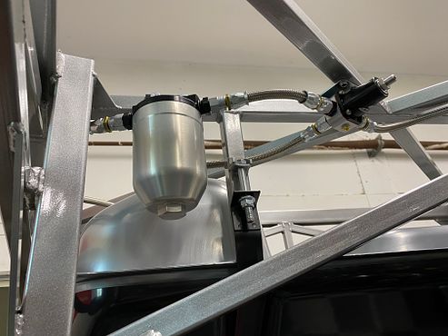
Either a typo or I'm just not explaining myself very well. I didn't suggest replacing the adjustable regulator you currently have. Only that another possible location is back by the tank. As many have done with the fixed regulator. Makes for a short return line and a single feed line to the front. That's what I did on my truck build and so far works fine. This is from the truck build. Didn't have the gauge on it at the time, but you get the idea. Yes, you have to crawl under there to adjust. Which for some will be a non-starter. But my experience is once set it doesn't need to be changed. My Coupe just finished it's third driving season and haven't touched the adjustable regulator since it was set.
Build 1: Mk3 Roadster #5125. Sold 11/08/2014.
Build 2: Mk4 Roadster #7750. Sold 04/10/2017.
Build Thread
Build 3: Mk4 Roadster 20th Anniversary #8674. Sold 09/07/2020.
Build Thread and
Video.
Build 4: Gen 3 Type 65 Coupe #59. Gen 3 Coyote. Legal 03/04/2020.
Build Thread and
Video
Build 5: 35 Hot Rod Truck #138. LS3 and 4L65E auto. Rcvd 01/05/2021. Legal 04/20/2023.
Build Thread. Sold 11/9/2023.
-
Senior Member
Ahhhhh. That's misunderstanding is totally on me. really appreciate your input (and patience).
-
Senior Member
Originally Posted by
KDubU
Looking good! Let me know if you need a hand or two one a major building task as I just moved back to Kennebunkport so not far away.
Great to have you back! Absolutely I'd appreciate a second set of hands for the big tasks as well as maybe a second set of eyes as a sanity check. Will send a PM.
-
Senior Member
Starting fuel lines, rear harness, more aluminum
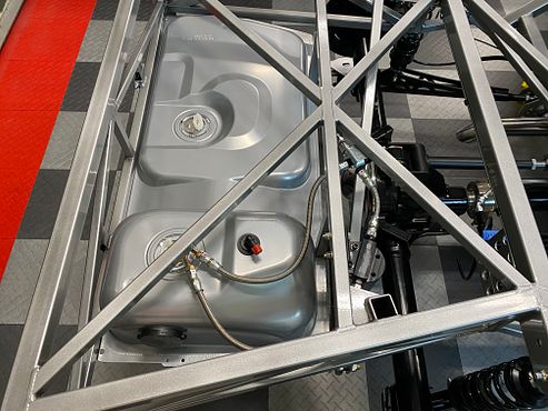
After much debate I landed on the "standard" firewall location for the fuel pressure regulator. Installed it and ran the return line back to the tank. I'm going with Fragola PTFE lines the entire way. Weighed the pros and cons of tubing vs braided stainless and decided on this route. I'm still waiting on the fuel filter from summit. After numerous pushouts on the trick flow canister filter, I cancelled the order and ordered the Aeromotive version. already shipped!
IMG_2497.jpgIMG_0742.jpg
Also in the above photo I moved the final hose clamp from the horizontal trunk member to the diagonal one closer the the wheel well for maintenance and dropping of the trunk should that need to happen. The horizontal 1x1 tube was convenient to reach without the trunk aluminum installed but would be a nightmare later on if the hose routed up and over that.
In the photo above and the one below, you can see I ran the rear harness down the tunnel and to the rough locations for the rear electrical connections. I still have to clamp into place.
IMG_0745.jpg
I am about to install the trunk aluminum floor panels. Prior to that I want to secure the rear harness, fill the pumpkin with appropriate fluids, and finalize the fuel lines. Anything else I should do while it's relatively exposed back there?


 Thanks:
  Likes:


 Reply With Quote


