Forte's

Visit our community sponsor

Thanks Thanks:  29
Likes Likes:  40
Page 2 of 20 FirstFirst 123412 ... LastLast
Results 41 to 80 of 779

Thread: EdwardBs Mk4 #8674 20th Anniversary Build

  1. #41
    Member BobCarter's Avatar
    Join Date
    Jun 2015
    Location
    Springfield, MO
    Posts
    98
    Post Thanks / Like

    Moog tie rod ends

    Edawardp- When you installed the Moog tie rod ends did you modify the steering arm to accomadate the taper of the Moog stud? I too ordered the Moog ends and see that the steering arm does not have a tapered hole to receive the mounting stud. The FFR tie rod end is not tapered and the Moog is. Just curious how you addressed this.

  2. #42
    Member BobCarter's Avatar
    Join Date
    Jun 2015
    Location
    Springfield, MO
    Posts
    98
    Post Thanks / Like
    A note to other builders- the front lower shock mounting bolt provided by FFR used in mounting the sway bar is a bit too short and as such does not fully pass through the elastic stop nut. When installing my sway bar I became concerned about this and purchased a 3 1/2 long bolt to replace the one which was furnished with the sway bar. This longer bolt now passes fully through the nylon insert in the nut and when torqued will hold better than the shorter bolt.

    Quote Originally Posted by edwardb View Post
    We’ve been back from our Oregon family visit for a little over a week now, and back on the build. While we were gone, several packages of parts arrived. Really happy to receive the spindles, which are now installed. Also received the driveshaft, even though I won’t need it for a long time. Also received a box of a number of smaller items. So the good news, I’m down to 8 backorder/missing parts. The bad news is that this includes the rear UCA’s, LCA’s, CV axles, and Wilwood brakes. So I’m not able to make any progress with the rear suspension, or install the brakes. Kits after mine are being delivered with some of these parts. Grrr… Back on the phone Monday.

    Used some of the time off to finalize some of the build plans, and order some more stuff. In other words, spend money… Decided to go ahead with GAS-N SS sidepipes. Even though the kit came with FF SS sidepipes, I’ve used the GAS-N’s on my previous builds, and love the looks, sound and overall quality. Got hold of Georgie and they’re already here. Works of art. Also going with the custom SS stainless headers. Called GP Headers (not Stainless Headers any more) and should have the Coyote double collector pipes in a few weeks. No hurry. Ordered and received an in-tank fuel pump from Breeze. Ordered and received a turn signal assembly from Russ Thompson along with my machined steering wheel hub. Found Russ also offers a trunk expansion box. I was going to make my own, but decided to get the one from Russ. Like all his stuff, it’s first class. Thanks to another forum member who contacted me, I also received a box of King DS Coyote mod panels and firewall that he decided not to use. Huge thanks. These forums are an amazing resource. I was considering making them myself. Now that I see them, would have been challenging.

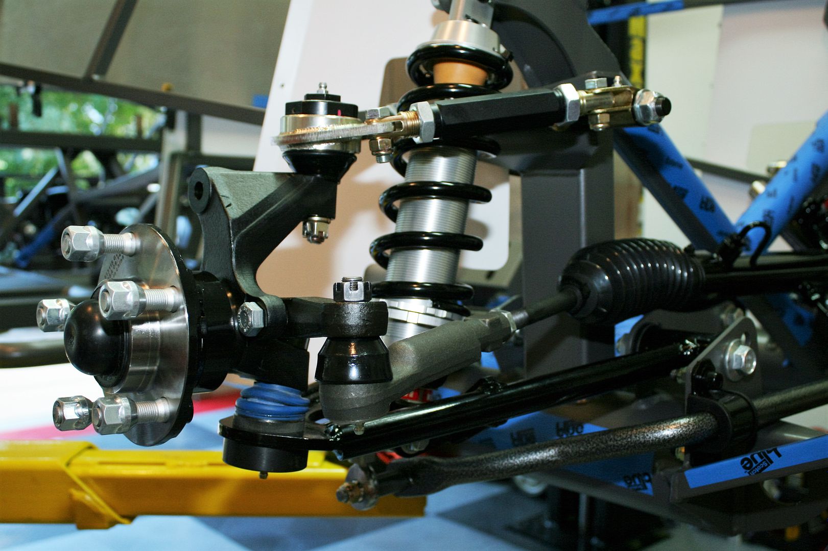
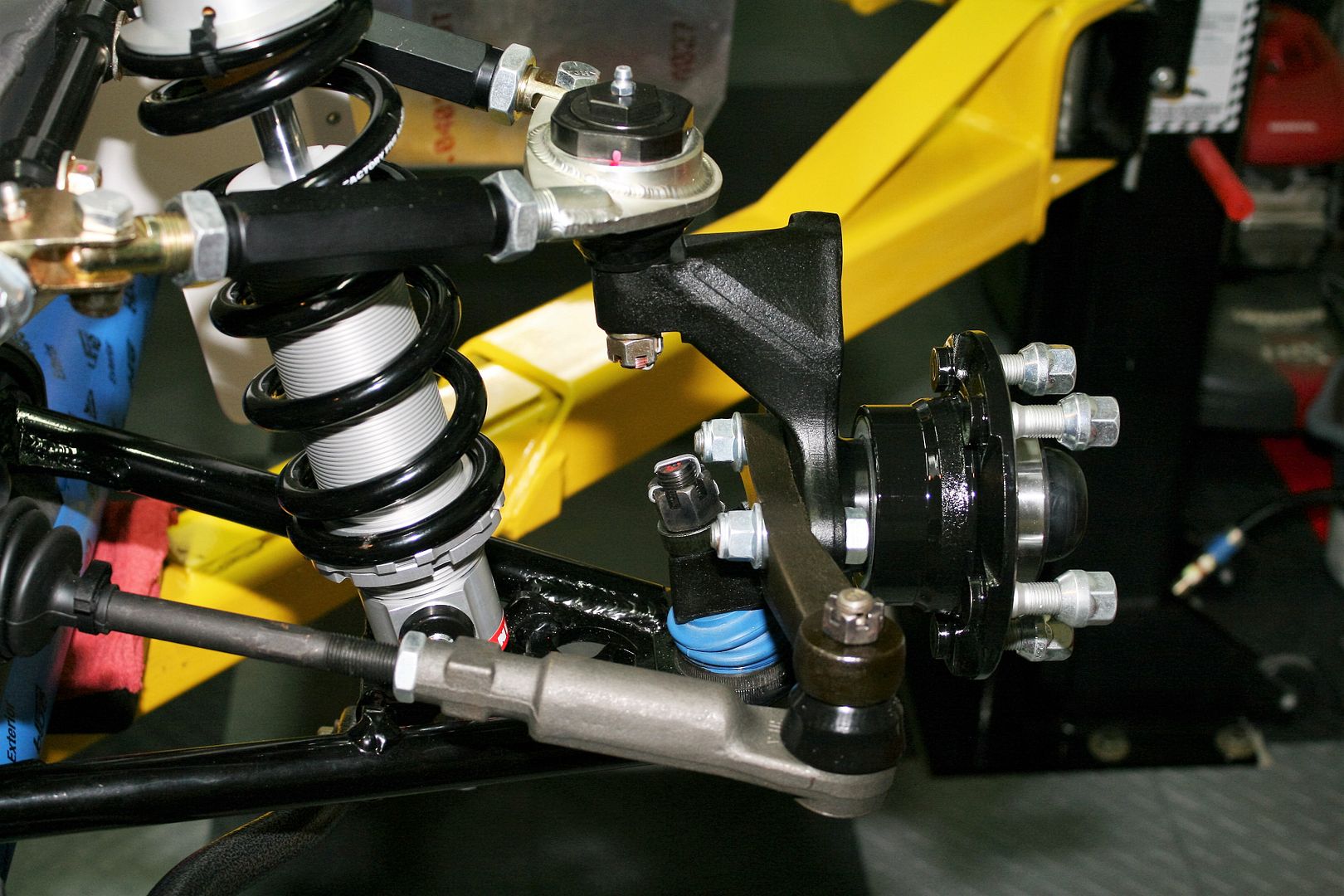
    So for some build updates, first thing was to get the newly received spindles installed. Everything went fine. The ball joint tapers pulled in and tightened without drama. I used the FF spacer for the lower ball joint, and needed a hardened washer for the Howe upper ball joints. The hubs slipped on with no sanding or large hammers. Nice smooth fit. Torqued the spindles nuts to 250 ft-lbs, which I’ve now decided is my personal limit. Ouch. As you can see from the pics, I pried off the tone rings. I have no plans for ABS, plus I think they’re kind of ugly. Then I put some POR15 on the back side of the hubs. Can’t help myself.


    I did a SWAG on the UCA for camber and caster, and then used a magnetic laser level to get the toe in the ballpark. I mainly wanted to do a sanity check on the length of the inner tie rods. I have about 1 inch of threads left on both sides of the threaded section on the tie rod ends. So there will be no cutting required. This the second time I’ve used this combination of Breeze PS rack and Moog tie rod ends. Perfect. Yes I know the cotter key isn’t installed in the castle nut yet. Later.


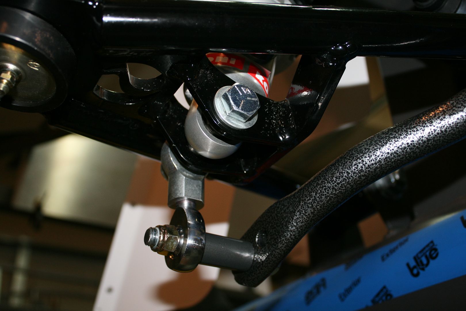
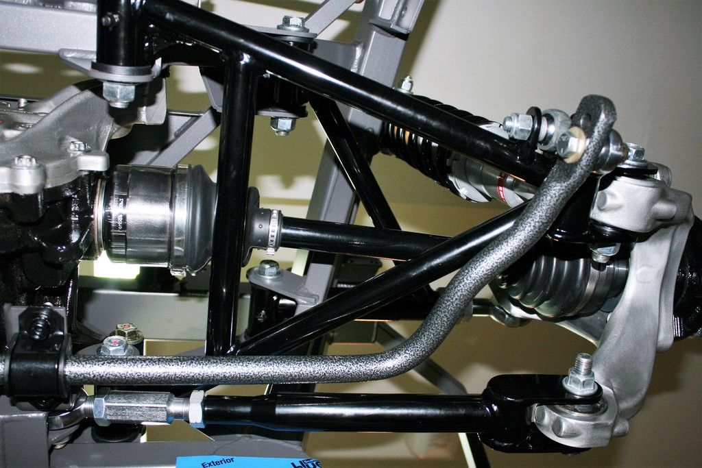
    The final item to wrap up the front suspension was the sway bar. I posted pictures of the front frame mounts before. Once the sway bar is bolted on up front, it’s attached to the underside of the LCA’s using a longer bolt on the lower shock mount, two rod ends, a bolt and spacer. The instructions show cutting all but 1/2 inch of threads from the male and female rod ends. Those things are HARD! But it’s done and turned out well. The instructions didn’t say so, but I put red Loctite on the rod ends before putting them together. I don’t have instructions yet for the rear sway bar, but the parts provided are all almost exactly the same, so I’m expecting a similar setup.


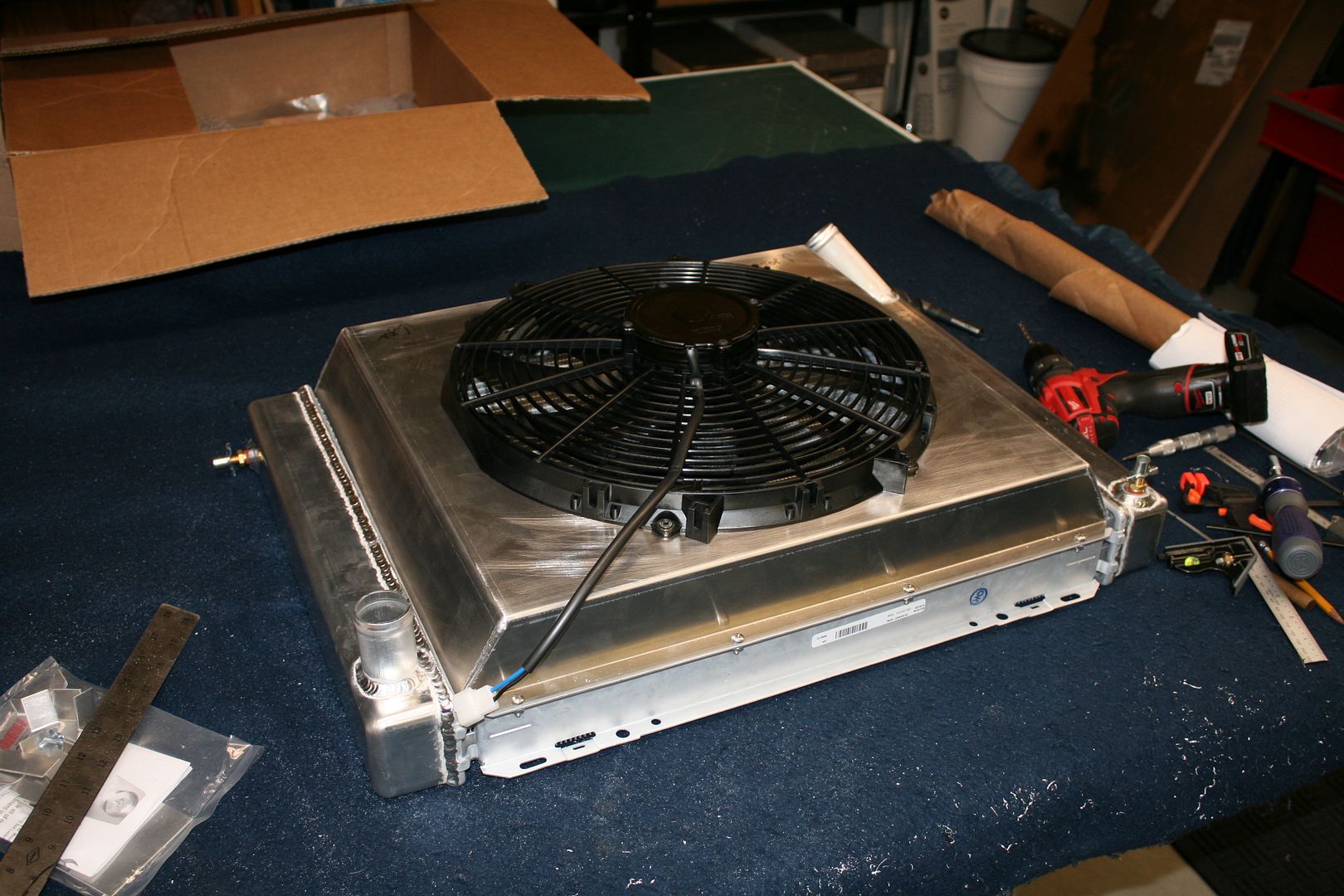
    I decided to cut the hole in the Breeze shroud and get that part ready for powder coat. The hole follows the inner outline of the FF supplied cooling fan. I put 10-32 nutserts in the mounting hole locations, which makes it real easy to install the fan and remove if necessary for service.



  3. #43
    Senior Member KDubU's Avatar
    Join Date
    May 2015
    Location
    Kennebunkport, ME
    Posts
    1,193
    Post Thanks / Like
    I notice you are using different boots on the LCA's and UCA's. The ones that come with the kit, dark blue, seem a bit liable to tear and I ordered some replacements from Summit but have not wanted to pull everything apart again to install. How do you find the ones with the kit and am curious why you have a few different ones?
    Kyle

    Complete Kit pickup 09/05/2015, 351w, QF680, 3.55, 3-Link, 15" Halibrands with MT's, Painted Viking blue with Wimbledon white stripes on 03/15/2017. Sold in 08/2018 and totally regret it.

  4. #44
    Senior Member
    Join Date
    May 2014
    Location
    Burlington, WI
    Posts
    697
    Post Thanks / Like
    Blog Entries
    1
    Edwardb,

    Thanks for the words of encouragement, and I will PM my email address to you. FFR has a great team over there and has been very helpful and responsive to my inquiries. But, as with many endeavors, frustration can get the best of you. Help is much appreciated.

    BobCarter,

    In addition to now having the IRS instructions, here are the ones sent with my paperwork:
    Wind wings
    Sun visor
    Windshield wipers(need for wisconsin) Go Pack..sorry, couldn't help myself.
    Hood hinges
    Emergency brake

  5. #45
    Senior Member edwardb's Avatar
    Join Date
    Feb 2011
    Location
    Lake Orion, Michigan
    Posts
    10,857
    Post Thanks / Like
    Quote Originally Posted by KDubU View Post
    I notice you are using different boots on the LCA's and UCA's. The ones that come with the kit, dark blue, seem a bit liable to tear and I ordered some replacements from Summit but have not wanted to pull everything apart again to install. How do you find the ones with the kit and am curious why you have a few different ones?
    The LCA boots are unchanged as received with the kit. Those blue ones I left alone. They are crimped in place (or held on somehow) and seemed OK to me. I have similar ones on my completed Mk4 that's done and driving. They are holding up fine. For the UCA, I switched to Howe Racing ball joints as I described earlier in the thread. They don't come with boots, but that's OK because I really like the Energy Suspension boots. So for the UCA, those are the Energy Suspension 5.13102G boots. That part number contains both upper and lower. I just used the one pair. Less than $10 for all four. For the steering tie rod ends, those are Energy Suspension 9.13101G boots. About $7.00 for the pair. The boots supplied with the kit are maybe OK. But you can find lots of instances where they haven't lasted the life of the build. Maybe because the suspension is hanging at full droop for extended periods of time and they get distorted and crack? Whatever the reason, easy and cheap to put better ones in now. Much more work later. I found the best price for the boots on Amazon. If they have what you're looking for, their car part prices are usually pretty good.
    Build 1: Mk3 Roadster #5125. Sold 11/08/2014. Build 2: Mk4 Roadster #7750. Sold 04/10/2017. Build Thread
    Build 3: Mk4 Roadster 20th Anniversary #8674. Sold 09/07/2020. Build Thread and Video. Build 4: Gen 3 Type 65 Coupe #59. Gen 3 Coyote. Legal 03/04/2020. Build Thread and Video
    Build 5: 35 Hot Rod Truck #138. LS3 and 4L65E auto. Rcvd 01/05/2021. Legal 04/20/2023. Build Thread. Sold 11/9/2023.

  6. #46
    Senior Member
    Join Date
    May 2014
    Location
    Burlington, WI
    Posts
    697
    Post Thanks / Like
    Blog Entries
    1
    A question on ball joints as others may notice the same thing I do. The ball joints for the front LCAs, as mentioned, appear to be pressed into the control arm and the boots are secure. However, the left one's threaded shaft is impossible to rotate without the tap of a plastic mallet. The right side ball joint moves rather freely like a joystick. I applied synthetic grease to both but the left one shows no improvement. Should I be concerned? And if so, with which one?

    Has anyone else found this to be the case? BTW, I may have been one of the fortunate ones to have the upper ball joints go in easily.

  7. #47
    Senior Member edwardb's Avatar
    Join Date
    Feb 2011
    Location
    Lake Orion, Michigan
    Posts
    10,857
    Post Thanks / Like
    Quote Originally Posted by ThickCobra View Post
    A question on ball joints as others may notice the same thing I do. The ball joints for the front LCAs, as mentioned, appear to be pressed into the control arm and the boots are secure. However, the left one's threaded shaft is impossible to rotate without the tap of a plastic mallet. The right side ball joint moves rather freely like a joystick. I applied synthetic grease to both but the left one shows no improvement. Should I be concerned? And if so, with which one?

    Has anyone else found this to be the case? BTW, I may have been one of the fortunate ones to have the upper ball joints go in easily.
    Both of my LCA ball joints were pretty tight. Probably similar to what you're describing for the one. For the one that moves freely, IMO unless there is any play at all, it's OK. You don't want the front suspension to bind, but it's stiff by design plus even more when it's brand new. During assembly, check that both UCA and LCA move OK individually after torquing down the bolts. They will be tight, LCA a bit more, but still should move with a little push. Then when you install the spindles, before you put in the coilovers, again check for free movement of the entire assembly. Everything will be stiff, but you should be able to get everything to move fairly easily. At that point, your ball joints are also moving. If it still doesn't seem right, then I would call FF. But I'm betting it's OK. Once you add the coilovers and sway bars (if you're using them) you can't really move the suspension by hand any more, so you can't tell anything at that point.

    Your experience with the upper ball joints is interesting. Many report trouble with this, and some like me just give up. Sure don't know where the variation is. As I documented, I couldn't get two different brands to go in. That would suggest the UCA's. But the Howe Racing parts went in smooth as could be. Strange.
    Last edited by edwardb; 12-06-2015 at 09:27 AM.
    Build 1: Mk3 Roadster #5125. Sold 11/08/2014. Build 2: Mk4 Roadster #7750. Sold 04/10/2017. Build Thread
    Build 3: Mk4 Roadster 20th Anniversary #8674. Sold 09/07/2020. Build Thread and Video. Build 4: Gen 3 Type 65 Coupe #59. Gen 3 Coyote. Legal 03/04/2020. Build Thread and Video
    Build 5: 35 Hot Rod Truck #138. LS3 and 4L65E auto. Rcvd 01/05/2021. Legal 04/20/2023. Build Thread. Sold 11/9/2023.

  8. #48
    Senior Member edwardb's Avatar
    Join Date
    Feb 2011
    Location
    Lake Orion, Michigan
    Posts
    10,857
    Post Thanks / Like
    Quote Originally Posted by BobCarter View Post
    A note to other builders- the front lower shock mounting bolt provided by FFR used in mounting the sway bar is a bit too short and as such does not fully pass through the elastic stop nut. When installing my sway bar I became concerned about this and purchased a 3 1/2 long bolt to replace the one which was furnished with the sway bar. This longer bolt now passes fully through the nylon insert in the nut and when torqued will hold better than the shorter bolt.
    Yep, same here. Easy fix. It's a widely available Grade 5 1/2"-13 hex head bolt. I have a very well stocked Ace Hardware about 2 miles from my house. They know me well. Not the first (or last) piece of hardware that gets changed.

    Quote Originally Posted by BobCarter View Post
    Edawardp- When you installed the Moog tie rod ends did you modify the steering arm to accomadate the taper of the Moog stud? I too ordered the Moog ends and see that the steering arm does not have a tapered hole to receive the mounting stud. The FFR tie rod end is not tapered and the Moog is. Just curious how you addressed this.
    Oops, sorry I missed this question. First, no I didn't modify anything. I assume we're talking about the ball joint studs on the Moog tie rod ends? If so, they're tapered exactly like the FFR supplied ones, and drop into the spindle steering arms perfectly. Any chance you have the steering arms on upside down, and trying to push them through the smaller side? PM sent.
    Last edited by edwardb; 09-24-2015 at 08:57 PM.
    Build 1: Mk3 Roadster #5125. Sold 11/08/2014. Build 2: Mk4 Roadster #7750. Sold 04/10/2017. Build Thread
    Build 3: Mk4 Roadster 20th Anniversary #8674. Sold 09/07/2020. Build Thread and Video. Build 4: Gen 3 Type 65 Coupe #59. Gen 3 Coyote. Legal 03/04/2020. Build Thread and Video
    Build 5: 35 Hot Rod Truck #138. LS3 and 4L65E auto. Rcvd 01/05/2021. Legal 04/20/2023. Build Thread. Sold 11/9/2023.

  9. #49
    Not a waxer Jeff Kleiner's Avatar
    Join Date
    Feb 2011
    Location
    Bloomington, Indiana
    Posts
    8,703
    Post Thanks / Like
    Quote Originally Posted by edwardb View Post
    ...I have a very well stocked Ace Hardware about 2 miles from my house. They know me well...
    Me too---in fact on more than one occasion I've been asked questions by customers who think I work there

    Jeff

  10. #50
    Senior Member
    Join Date
    May 2014
    Location
    Burlington, WI
    Posts
    697
    Post Thanks / Like
    Blog Entries
    1
    Quote Originally Posted by Jeff Kleiner View Post
    Me too---in fact on more than one occasion I've been asked questions by customers who think I work there

    Jeff
    And if your support to fellow builders is any indication, I would suspect you help customers with their questions.

  11. #51
    Senior Member edwardb's Avatar
    Join Date
    Feb 2011
    Location
    Lake Orion, Michigan
    Posts
    10,857
    Post Thanks / Like

    This Week's Update

    No big changes to report with my backorder situation, mainly affecting the IRS and Wilwood brakes. I’m in regular contact with FF, and I believe they are trying hard to get my remaining parts. But no firm dates at this time. I’m not the only one in this situation. I want the IRS installed before starting fuel and brake lines, which is really what I want to be doing next. I’ve not done IRS before, and I don’t think anyone has done the 2015 Mustang one yet. So I’m just not comfortable running any lines before I see exactly what I’m dealing with. Then need the Wilwood brakes to finalize all four corners plus e-brake.

    Meanwhile, I’ve kept busing making progress in other areas. Decided to tackle the fuel tank assembly and installation. The first two kits I built were not donors but were basic kits. So I bought my own fuel tank in each case. They were pretty generic Spectra tanks. Domestically made, unpainted, etc. This complete kit has the FF supplied tank. It’s not marked, but just based on the box and other components, it appears to be imported. Quality seems decent. It’s painted, which is nice. I like the provided cover better than the standard Ford part. It’s kind of a shiny plastic, and doesn’t have the bump-in for the differential which is out of place for our builds. So gives a nice clean appearance. Important for under the car, right? One caution I would make about the tank. Use a file, sandpaper, emery cloth, whatever, and clean up the openings. They are rough and razor sharp. I can’t think that would be nice on the rubber seals used in a couple openings, or just to protect from cutting yourself. I blew out the tank real well to make sure it was clean inside. Then started to install various components.

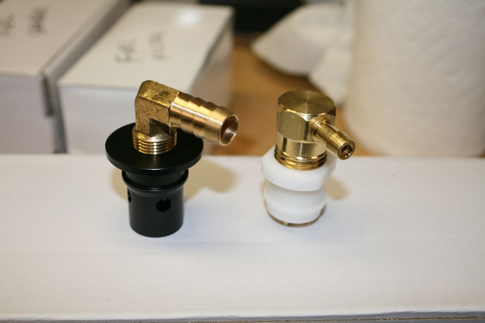
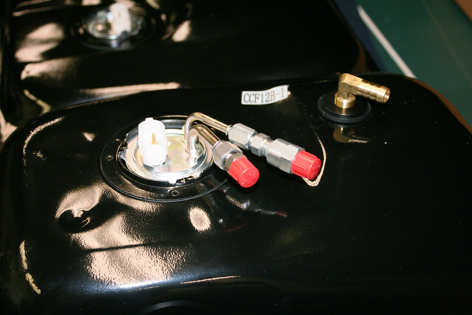
    A problem frequently mentioned in the past on the forums is having to fill the tank slowly or it backs up, flows over, etc. I think this is mainly related to using a donor fill tube, something that isn’t done too much any more. But one suggested solution is a larger tank vent. I’ve done this on both of my builds to date. They didn’t have donor fill tubes, and I never had fill problems. But I went ahead and got one for this build as well. It’s Breeze #70648. You can see in this pic the difference between the Breeze part on the left and the kit vent on the right. What doesn't show is the much larger check ball and valve on the Breeze piece. It pushes in through the kit supplied gasket in top of the tank.


    Next up was the fuel level sending unit. I used the kit supplied part. I did check its operation before installing. First just to make sure it was alive, but also to confirm the measurement range. With a digital multimeter clipped across the leads, measured the ohms at empty (float down) and full (float up). It registered 15.5 – 165 ohms confirming it was doing something. For my last build, the Ford sending unit had the same reading, which turned out to be one of the ranges available in the Speedhut gauge during calibration, so easy to pick the right one if not already using that range.


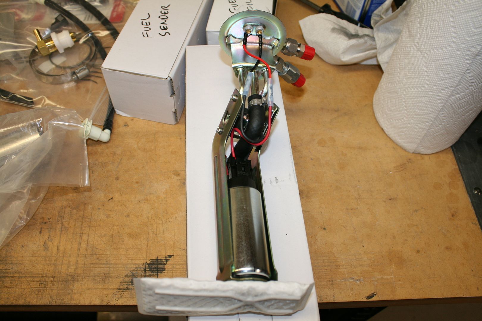
    I need an electric fuel pump for my Coyote build, and decided early on to do an in-tank pump. There are advantages and disadvantages for in-tank and external. But I think it’s generally accepted the in-tank pumps run cooler and are a little quieter. The main downside is they are harder to service or replace. But with the access panel in the trunk, not too bad, so going that way. The Coyote recommended pump is a 255L/Hr unit. I went with one from Breeze. Mark sets it up with a Walbro pump and oversized 1/4 inch inlet and 5/16 inch outlet. Here I have it ready to go into the tank with the filter sock attached.


    Here is the top of the tank with the fuel pump and vent installed. I also added -6AN adapters for the inlet and outlet tubes from Breeze. I will use SS flex from here to the rigid fuel lines about 12 inches away on the chassis.


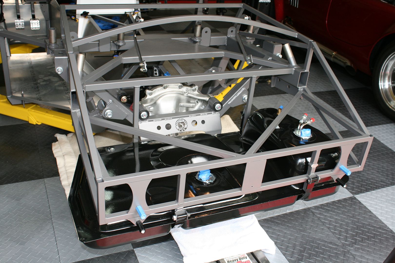
    I use a floor jack with a piece of plywood and cushioned with a blanket to lift the tank into position under the chassis. Don’t forget the little plastic bumpers on the bottom of the tank support tubes. Also don’t overlook the manual instructions to straighten the bent seam on the tank by the straps. I admit I missed this at first. The tanks I’ve purchased before weren’t pre-bent like that. The tank won’t sit properly unless the seam is flat. I did have to “adjust” the two front tank supports a bit with a dead blow hammer. The PS about ¼ inch. The DS about ½ inch. They needed to be moved forward just a bit so the bumpers sat flat on the tank seam without running into the tank sides. With the cover in place, the straps snugged up fine and all is good.


    Here’s a nice surprise. Looks like the fuel filler isn’t going to interfere with the frame rail. This is a common problem many have reported, and I experienced on my last build requiring me to shim the tank down a bit. I’m not sure what changed. Maybe FF extended the tank mounting tubes a bit. Or moved the frame rail some. Whatever, happy to see nothing special required here.

    Last edited by edwardb; 09-27-2015 at 12:02 AM.
    Build 1: Mk3 Roadster #5125. Sold 11/08/2014. Build 2: Mk4 Roadster #7750. Sold 04/10/2017. Build Thread
    Build 3: Mk4 Roadster 20th Anniversary #8674. Sold 09/07/2020. Build Thread and Video. Build 4: Gen 3 Type 65 Coupe #59. Gen 3 Coyote. Legal 03/04/2020. Build Thread and Video
    Build 5: 35 Hot Rod Truck #138. LS3 and 4L65E auto. Rcvd 01/05/2021. Legal 04/20/2023. Build Thread. Sold 11/9/2023.

  12. #52
    Senior Member edwardb's Avatar
    Join Date
    Feb 2011
    Location
    Lake Orion, Michigan
    Posts
    10,857
    Post Thanks / Like

    This Week's Update (continued)

    The tank is now back off, all the openings taped up, and ready to install for the last time later in the build. I cut off the extra tab above the strap connection on the PS. Did the same thing on my last build as well. Although I haven’t experienced it, there are apparently some tank strap setups that need this higher mounting location. But this one doesn’t, so off it comes. I’ll put a little paint on the bare metal, and add a piece on the trunk aluminum to cover the matching opening. It’s an obstruction that is nice to not have in the trunk. Some go even further and lower the other mount out of the trunk like the DS. That requires welding and shortening the strap. It’s far enough down in the trunk that it’s not an issue IMO.


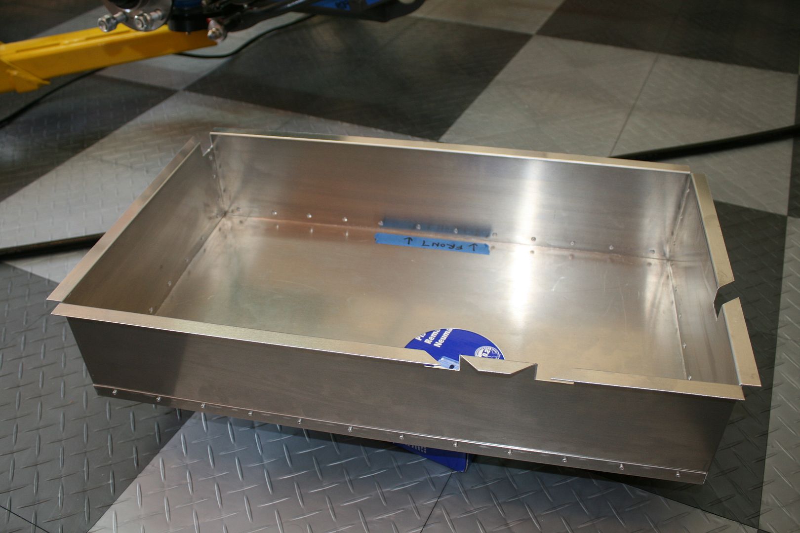
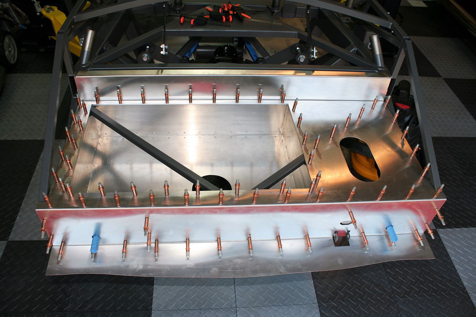
    I assembled the Russ Thompson trunk box mentioned in my last update, and used the now installed tank to confirm the location of the trunk box. I centered the sender access panel over the sending unit, and confirmed all else had adequate clearance. Then located the trunk aluminum, marked and drilled for rivets, and started the first of many drilling and cleco sessions. With the required opening for the trunk box now determined, cut out the hole and drilled and cleco’d the trunk box into place. An often asked question on the forums is how many clecos does it take to build one of these? Here I demonstrate it takes a lot. Couldn’t help myself… Really, not that many are required. In these pics you can also see that I’m leaving in the chassis tubing through this area. Many remove these pieces when installing a trunk box, and (hopefully) weld in new pieces below the box and above the tank. I’m OK with the minor obstruction, and happier to not mess with FF’s chassis design. It still gives a ton of additional space.


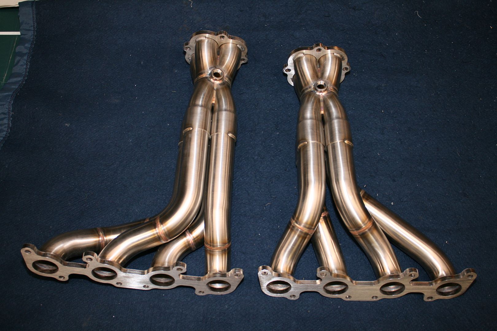
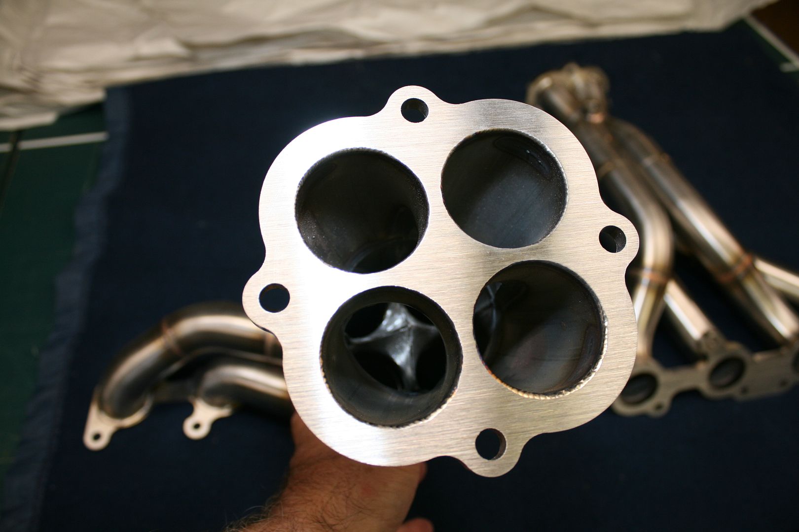
    My last update for this week is a nice surprise. Part of my Coyote build plan is stainless headers from GP Headers. A little over two weeks ago I called Kevin at GP Headers in Minnesota. He said he doesn’t stock them but only makes on order. No problem. Took my name and number and said he would call back in two weeks for shipping info. On Wednesday, he called and said they were ready. Exactly two weeks! Took my address and credit card number and they were on my porch on Friday. I’ve seen pictures, but not seen these in person. I’m not disappointed. Beautiful pieces and amazing workmanship. Of course the proof will be how they fit. But for now I’m a happy camper. In the second picture you can see the center spike in the collector. Similar piece where it goes back to 4 tubes right before the pipe flange.


    At this point I’m going to keep plugging away on sheet metal until my IRS parts are here.
    Build 1: Mk3 Roadster #5125. Sold 11/08/2014. Build 2: Mk4 Roadster #7750. Sold 04/10/2017. Build Thread
    Build 3: Mk4 Roadster 20th Anniversary #8674. Sold 09/07/2020. Build Thread and Video. Build 4: Gen 3 Type 65 Coupe #59. Gen 3 Coyote. Legal 03/04/2020. Build Thread and Video
    Build 5: 35 Hot Rod Truck #138. LS3 and 4L65E auto. Rcvd 01/05/2021. Legal 04/20/2023. Build Thread. Sold 11/9/2023.

  13. #53
    Carl carlewms's Avatar
    Join Date
    May 2012
    Location
    Nokesville, VA
    Posts
    1,125
    Post Thanks / Like
    I am not sure you can ever have enough Clecos!
    Mk 4 Roadster
    October 25, 2012 - Kit Arrives
    April 8, 2013 - Build Starts
    August 23, 2015 - Rolling Chassis/Engine & Transmission Installed
    March 26, 2016 - Go Cart

  14. #54
    Member BobCarter's Avatar
    Join Date
    Jun 2015
    Location
    Springfield, MO
    Posts
    98
    Post Thanks / Like
    Edward that IS a lot of Clecos! Good idea to remove the gas tank mount on PS. I see you have not installed your IRS members. Still dont have them? Control arms are a tight fit but feels good once installed. Cant wait for my CV shafts.
    [ATTACH]46032
    Attached Images Attached Images

  15. #55
    Senior Member edwardb's Avatar
    Join Date
    Feb 2011
    Location
    Lake Orion, Michigan
    Posts
    10,857
    Post Thanks / Like
    Quote Originally Posted by BobCarter View Post
    Edward that IS a lot of Clecos! Good idea to remove the gas tank mount on PS. I see you have not installed your IRS members. Still dont have them? Control arms are a tight fit but feels good once installed. Cant wait for my CV shafts.
    Nice pic. Looks good. No upper or lower control arms here. Or CV axles. Controls arms are supposed to be in production, and I'll get them as soon as their completed. CV axles are coming from their supplier. Supposedly any day now.
    Build 1: Mk3 Roadster #5125. Sold 11/08/2014. Build 2: Mk4 Roadster #7750. Sold 04/10/2017. Build Thread
    Build 3: Mk4 Roadster 20th Anniversary #8674. Sold 09/07/2020. Build Thread and Video. Build 4: Gen 3 Type 65 Coupe #59. Gen 3 Coyote. Legal 03/04/2020. Build Thread and Video
    Build 5: 35 Hot Rod Truck #138. LS3 and 4L65E auto. Rcvd 01/05/2021. Legal 04/20/2023. Build Thread. Sold 11/9/2023.

  16. #56
    Senior Member edwardb's Avatar
    Join Date
    Feb 2011
    Location
    Lake Orion, Michigan
    Posts
    10,857
    Post Thanks / Like

    IRS Assembly Completed

    This is a pretty important update. As the title says, the IRS installation is completed. A big milestone. The last few days have been good for backordered parts delivery. Received the upper and lower control arms and other misc stuff last week. Received the CV axles yesterday. Very nice pieces from The Driveshaft Shop. And the last pieces of hardware today. So no more excuses. I have one single item left on my backorder list, and that’s the Wilwood brakes. Pretty major item, but I can proceed for now. My understanding is they’re in production, but I don’t have an ETA.

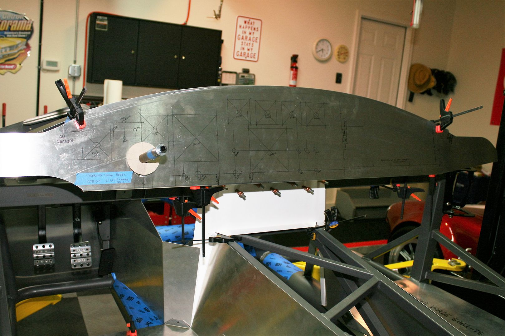
    Before getting into the IRS, a couple of other bits of progress while I was waiting for parts. I worked on my dash some. I was able to sell the provided assembled dash. It was nice enough, but a street layout and I really want the competition layout. So I have a blank dash and the first thing was to copy the layout from my current Mk4 to the blank. I spent a long time laying that out a couple years ago, focusing on not just the competition layout but also sight lines, ergonomics, etc. After driving this season, there’s nothing I would change. I like it a lot. So I’m starting there. Still have some decisions to make, like oil temp in or out, what indicator lights, can I do (or even need) a fan override with the Coyote ECU, etc. So I’ll decide those things before finalizing the layout. I will be doing a glove box. But still looking at options for that and the covering material. Also started fabbing the dash braces I’ll use. This is similar to my first two builds. A small one on each end that will also contain down lights for the footwells. And a larger one in the center that will have 12V outlets, various switches, and stuff mounted on the top side. They’ll be riveted to the two inch tube at the front, and attached to the dash edge with nutserts (what else?) through the bottom. These three make the dash quite solid, but still leave it open enough for some access if needed. Note the one by the steering column is not in the final location. It will be at the end of the dash. I have to notch it around some things still.


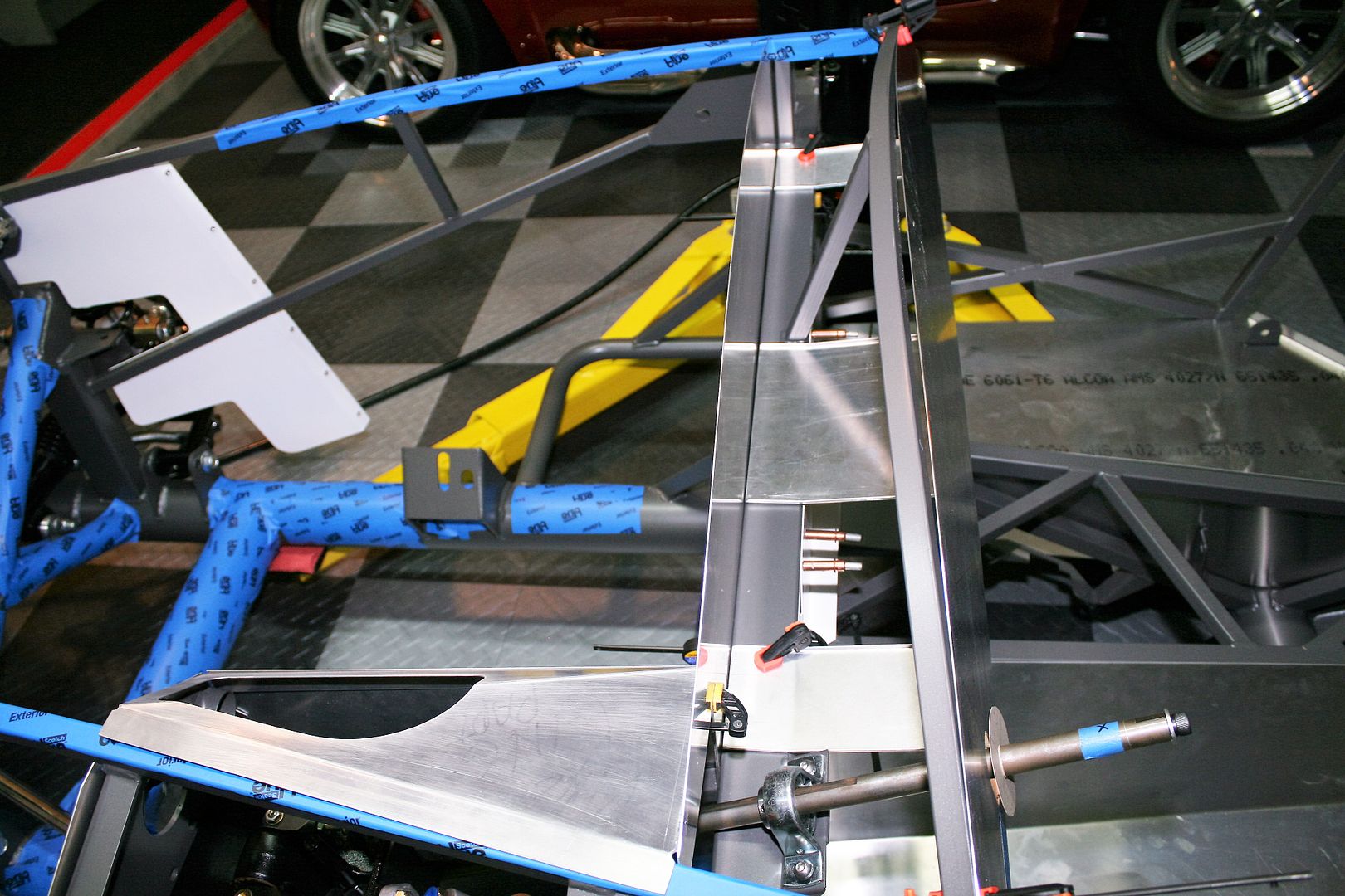
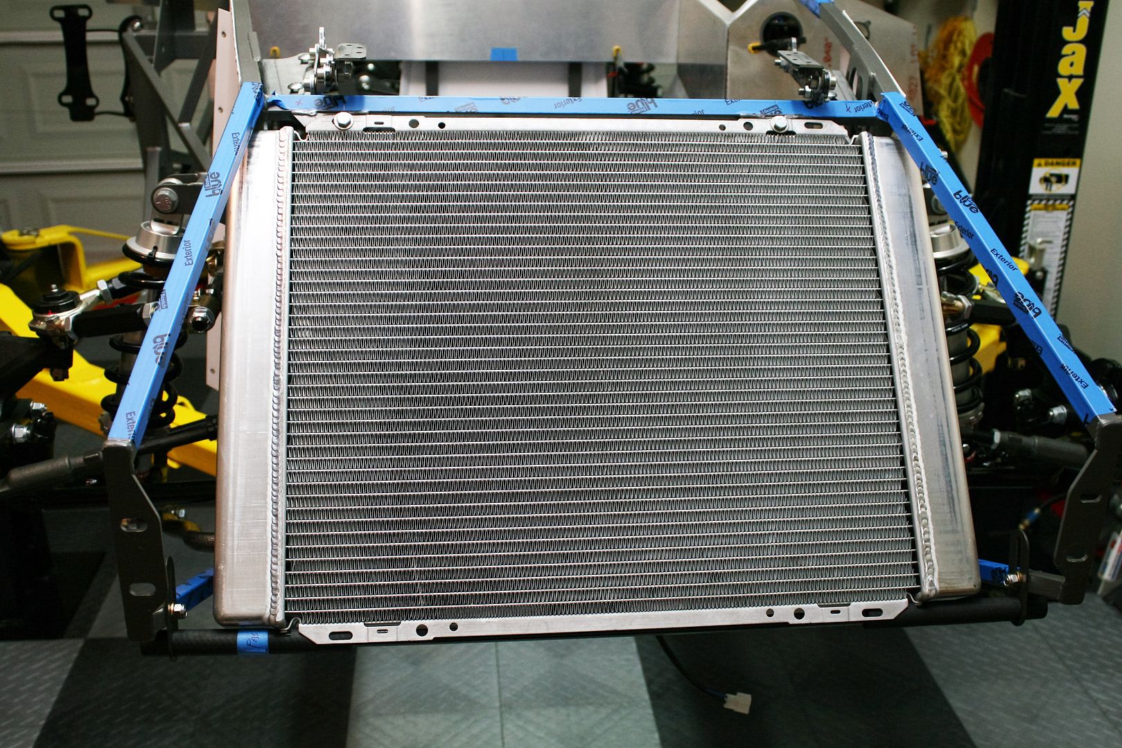
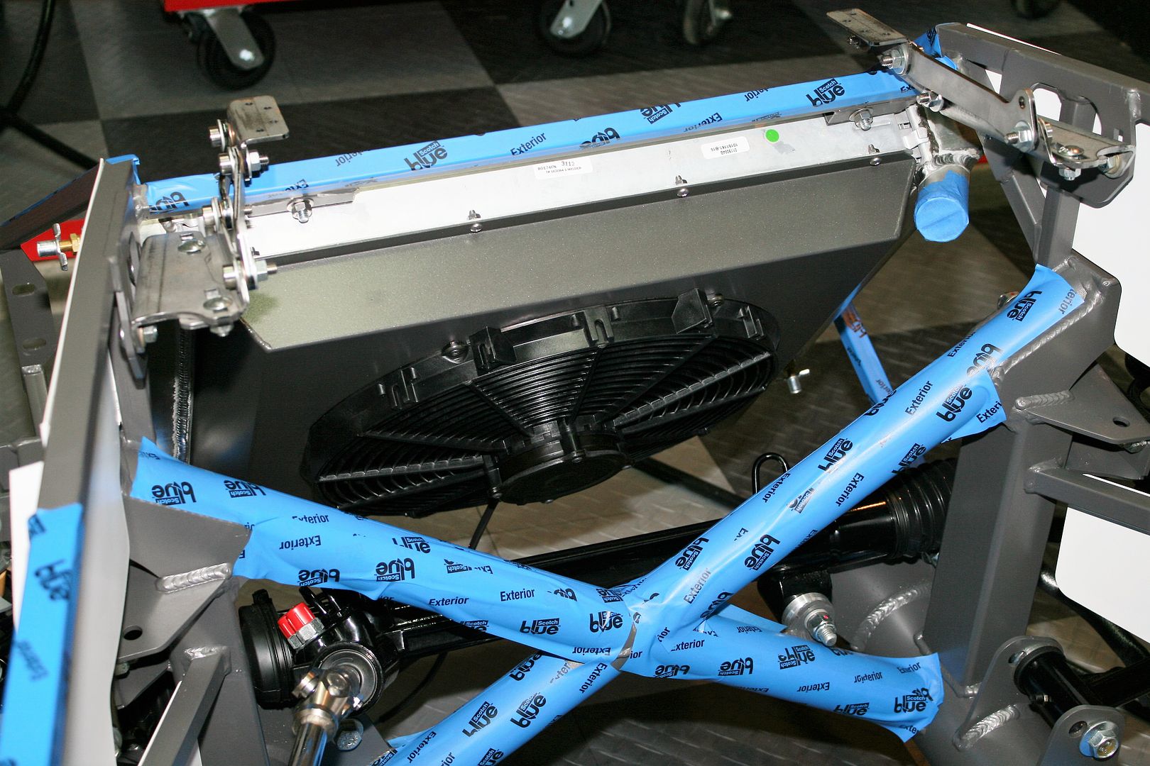
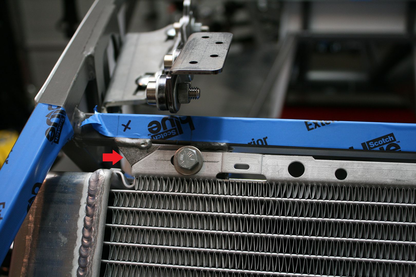
    The next thing I worked on was the radiator with cooling fan and shroud. In an earlier update I described getting the shroud ready. I sent it out for powder coat along with several other parts. They were able to match the silver/grey of the chassis very nicely. Just the other day we received the actual brands and codes for the Anniversary powder, so I’ll be checking into that before committing to all the aluminum panels. But for now, pretty good. I mounted the fan to the shroud, and then added the radiator. Then mounted in the chassis using the Breeze lower radiator mount. All quite straightforward. I mounted the radiator in the center of the opening. Did the same thing on my last build. The manual says 5/8 inch over toward the DS, but it doesn’t need to be IMO. This was discussed a bit in another thread the last few days. Won’t repeat it all here. Two small hints. While it’s likely OK, I think it’s a good idea to add a little cushion to the top mounting locations. I used some pieces of neoprene on my last build. That was OK. But this time used some tubing I had on hand. Just slightly thicker but not quite so hard as the neoprene. Slit the tubing and wrapped it around the front and bottom, held on with 3M weatherstrip adhesive. Then trimmed to fit. Turned out good and provides just a little “give” in the top mounting. The other thing to watch for is a slight interference between the radiator tank assembly and the mounting tube on the PS. You could go ahead and mount it that way, but the already pretty narrow mounting available on the radiator top would become even smaller because the radiator would be slightly lower on that side. I just undercut an angle on the mounting tube and it fits better I think. Did the same thing on my last build. You can see it in the close-up pic.


    You can also see in these pictures I assembled and temporarily placed the hood hinges. More fill-in work. I'll either paint or PC them later. Just a couple words about those. I believe all the steel parts (along with the aluminum panels) are laser cut. Really nice clean and precise parts. But the steel ones especially are left with pretty sharp edges. Plus seems that every part has one or two little “nibs” where I’m assuming the laser starts and stops and holds the part from falling out of the sheet. But those things can be nasty and can lead to unplanned blood donations. (Ask me how I know). Do yourself a favor and spend a little time with a file and some emery cloth and clean up the parts during assembly. For the hood hinges, I didn’t use the wavy washers. First time I’ve seen those. The best way I’ve found to assemble the hood hinges using the shoulder bolts is with two 3/8 inch ID washers for each bolt. One under the head of the bolt, then the hinge pieces and bushing oriented properly, then another 3/8 inch ID washer. There should be just a little of the bolt shoulder remaining, and make sure the washer fits over that shoulder. Then add the nut and tighten to suit. Works perfect. I was able to find enough washers in my junk drawer to get the job done. You need to be selective to get the right thickness. Same for the trunk hinges and also the doors. Although I found the doors are assembled fine from the factory and I’m not doing anything to them. If you look really close in the pictures (and I know some of you do!) you’ll notice I don’t have the lock nuts on the hood hinges. Or radiator for that matter. I have a supply of 5/16 and 3/8 inch plain nuts (the most common sizes), and do a lot of the mock-up with those. I don’t use the actual lock nuts until final assembly. Easier plus reduces wear on the lock nuts so they can do their job.

    One other update. As mentioned early in this thread and in another separate thread, I purchased a complete “zero miles take-off” 2015 Mustang IRS assembly, including not only the parts required for the build, but also the stock CV axles, upper and lower control arms, even the actual frame assembly. I was hoping to sell the leftover stuff and recover a little money. No luck so far. Had them on Craigslist for a couple weeks with zero responses. Hard to believe with Craiglist. No spam or anything. Just finished a 7 day no reserve eBay action for each. Had quite a few lookers and watchers, but only one sale. A pair of lower control arms for 99 cents. Good grief. What a waste. I’ll throw the stuff in my “not used” pile and see what happens I guess. One thing I did notice though. The CV axles I received yesterday from Factory Five, while shorter (and beefier) than the stock ones, have the same exact ends as the stock axles I have. Same FoMoCo laser markings and part numbers. So at the very least these could be spare parts if ever needed.

    Related to this, I happen to run across that Ford Racing is now selling the 2015 Mustang center sections and knuckles/hubs separately. Four months ago I couldn’t find anything other than service parts or the zero mile take-offs I ended up using. Google M-4001-88355. That’s the Ford Racing part number for a 3.55 cast iron center section. List just over $1k. Available multiple places for a bit less. M-4001-88373T is the 3.73 cast iron Torsen center section. List over $2K. Expensive piece. The knuckles with hubs are Ford Racing part number M-5970-M. List price a little over $500. Availability on those looks to be a little limited. Interesting for both the center sections and knuckles the Ford Racing pages specifically say “Can be used in kit car custom builds.” So looks like the market might be catching up. Posting this because I know some reading this thread may be looking at a future 2015 Mustang IRS build.
    Last edited by edwardb; 10-08-2015 at 12:18 AM.
    Build 1: Mk3 Roadster #5125. Sold 11/08/2014. Build 2: Mk4 Roadster #7750. Sold 04/10/2017. Build Thread
    Build 3: Mk4 Roadster 20th Anniversary #8674. Sold 09/07/2020. Build Thread and Video. Build 4: Gen 3 Type 65 Coupe #59. Gen 3 Coyote. Legal 03/04/2020. Build Thread and Video
    Build 5: 35 Hot Rod Truck #138. LS3 and 4L65E auto. Rcvd 01/05/2021. Legal 04/20/2023. Build Thread. Sold 11/9/2023.

  17. #57
    Senior Member edwardb's Avatar
    Join Date
    Feb 2011
    Location
    Lake Orion, Michigan
    Posts
    10,857
    Post Thanks / Like

    IRS Assembly Completed (continued)

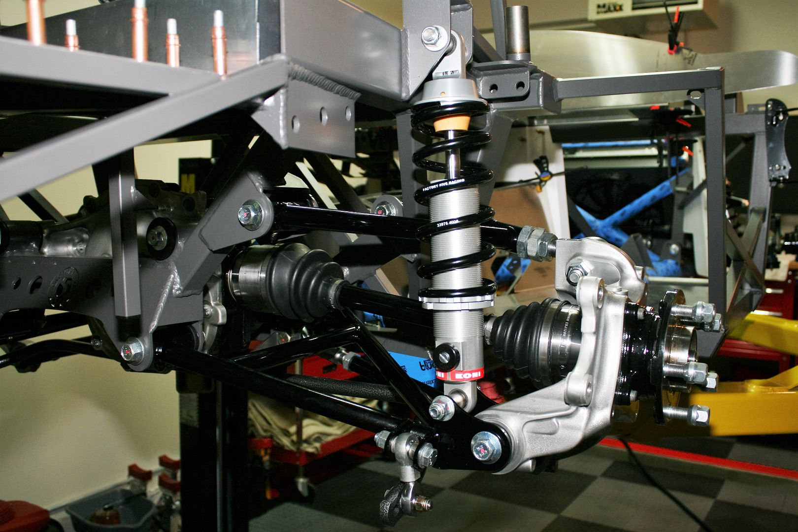
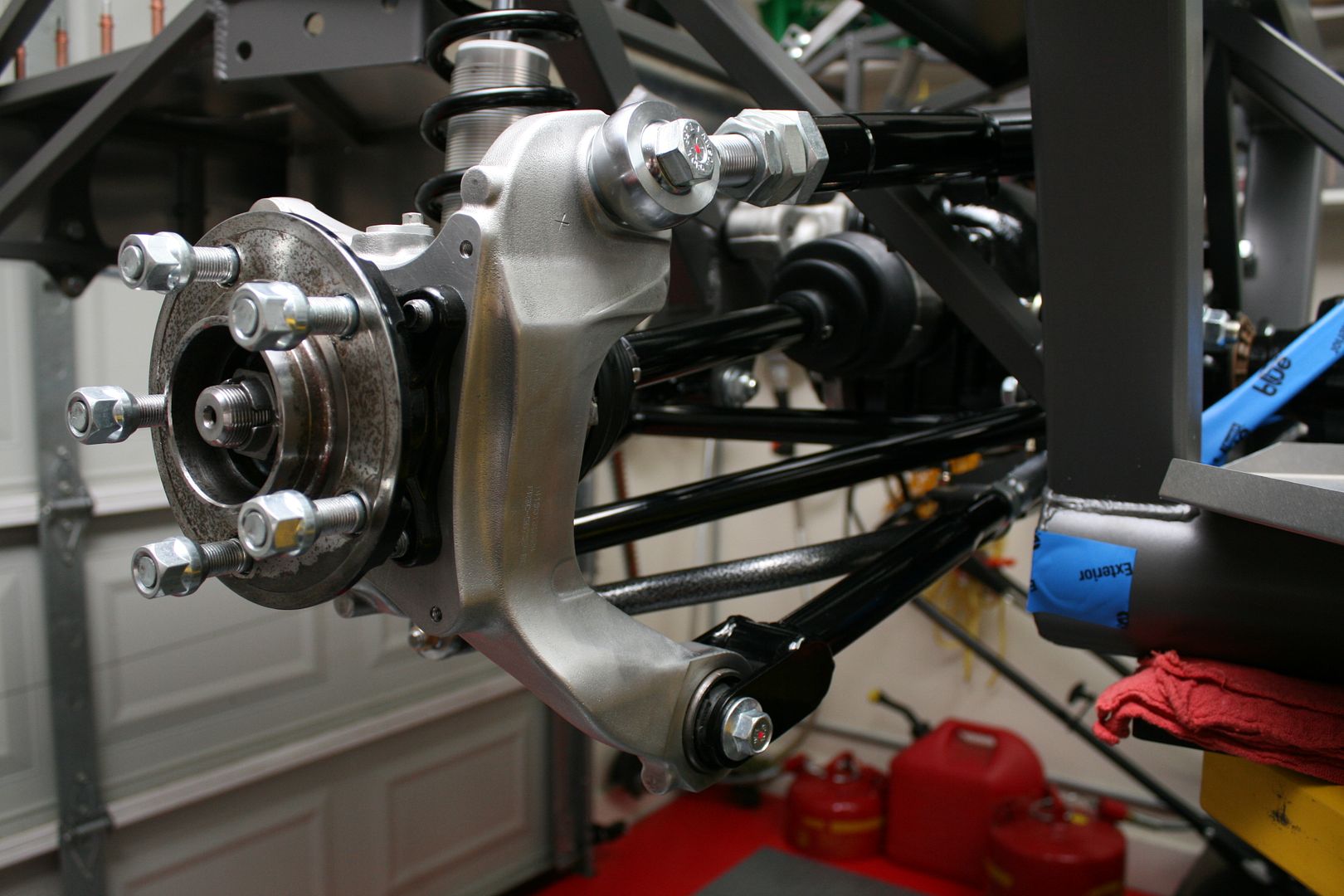
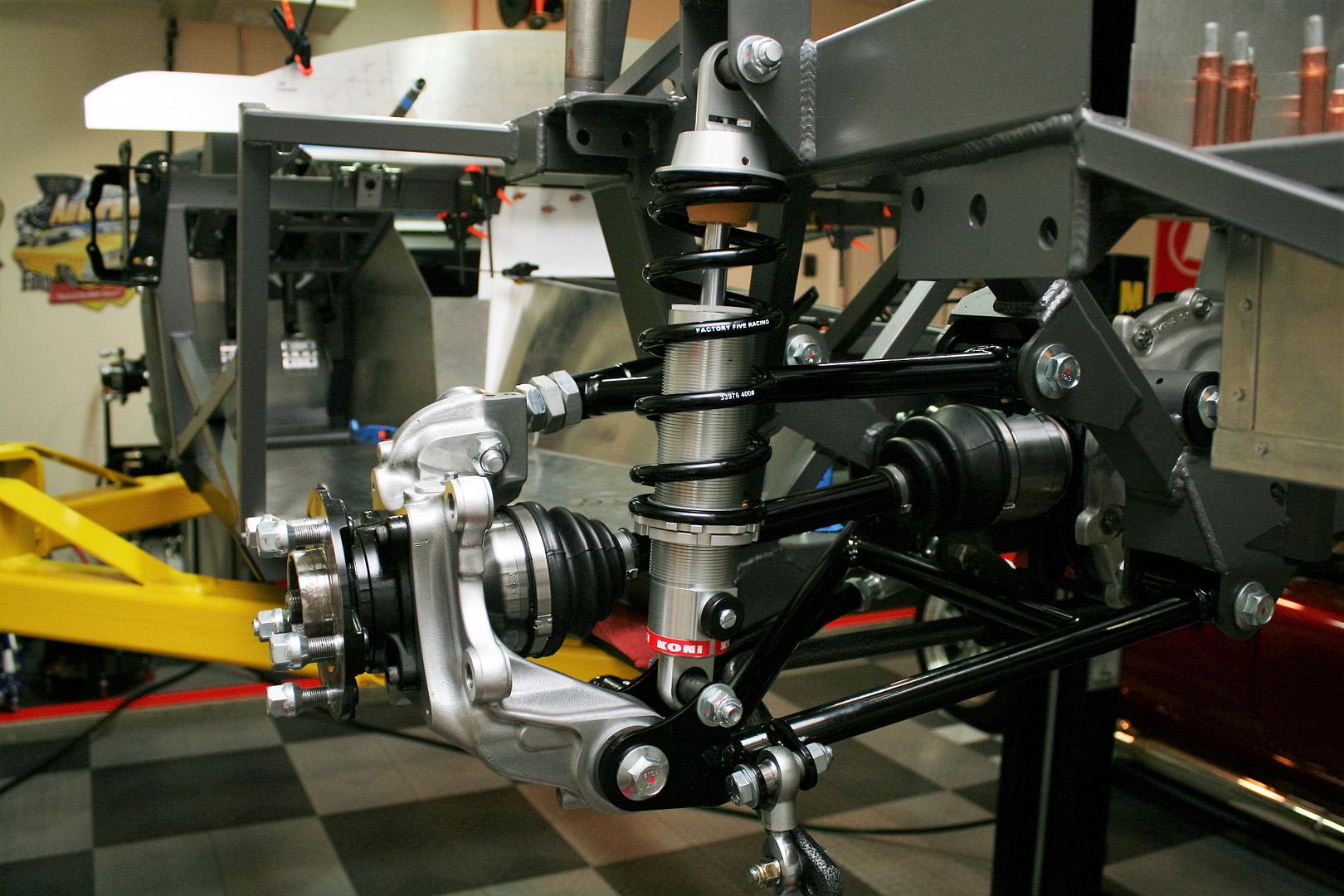
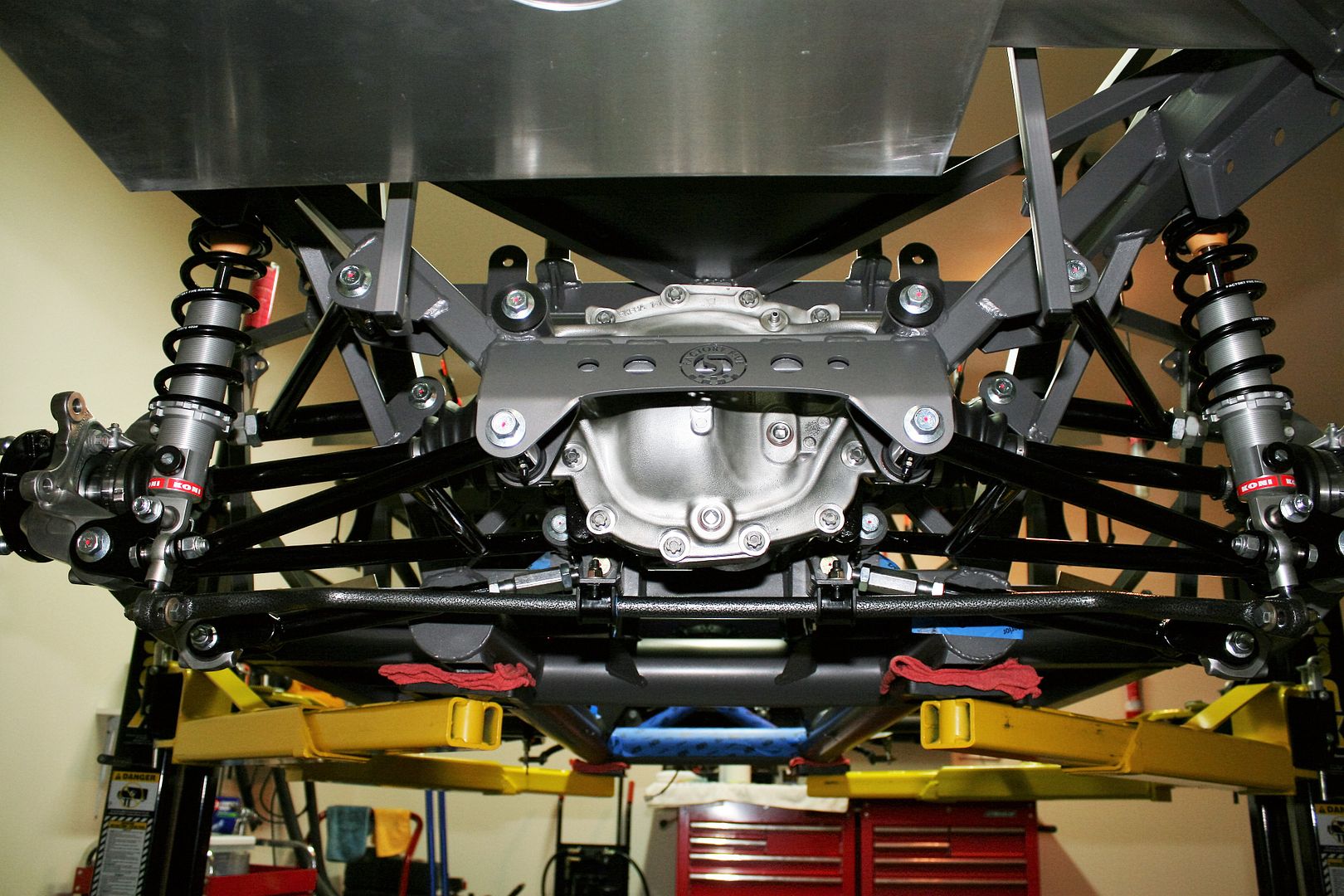
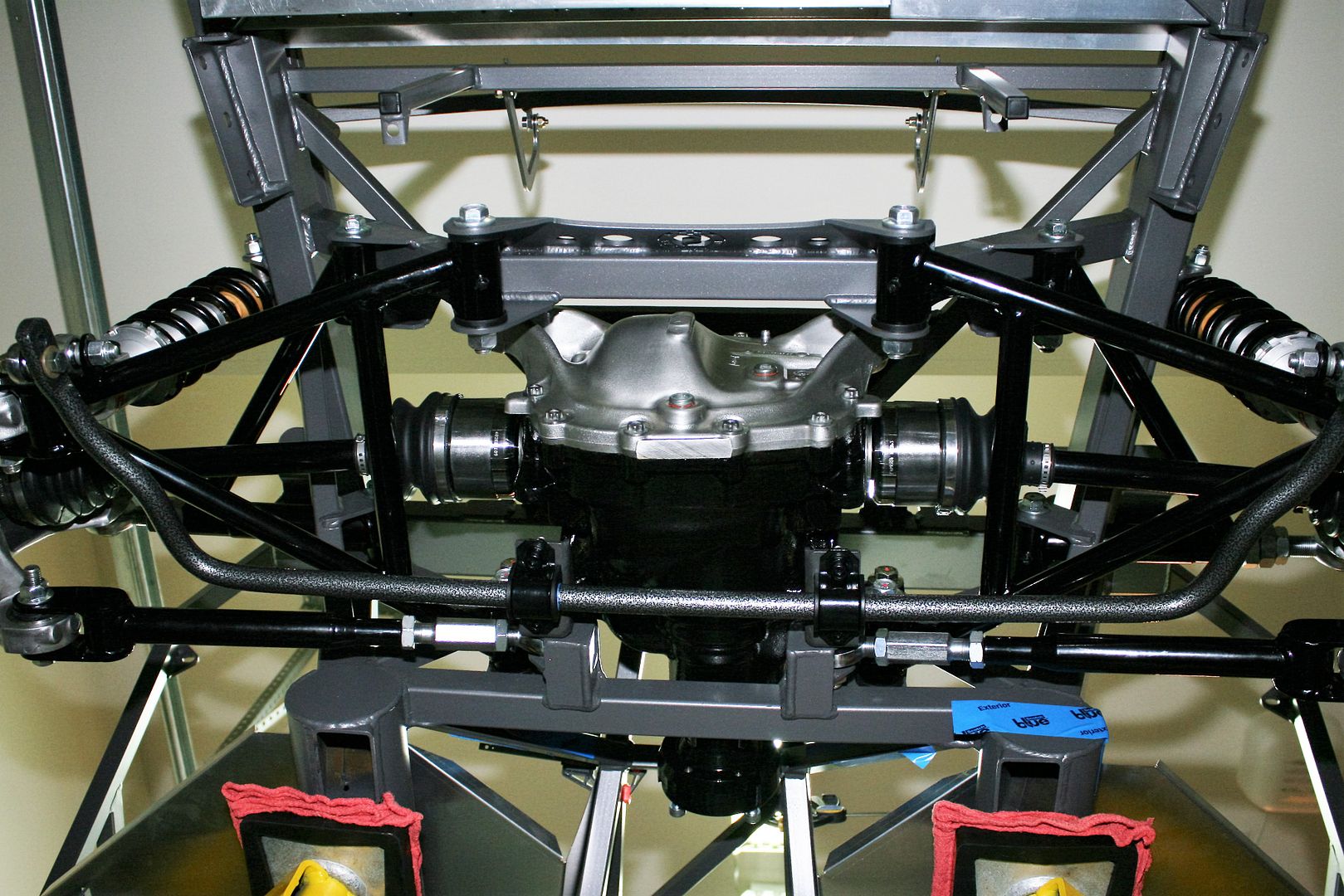
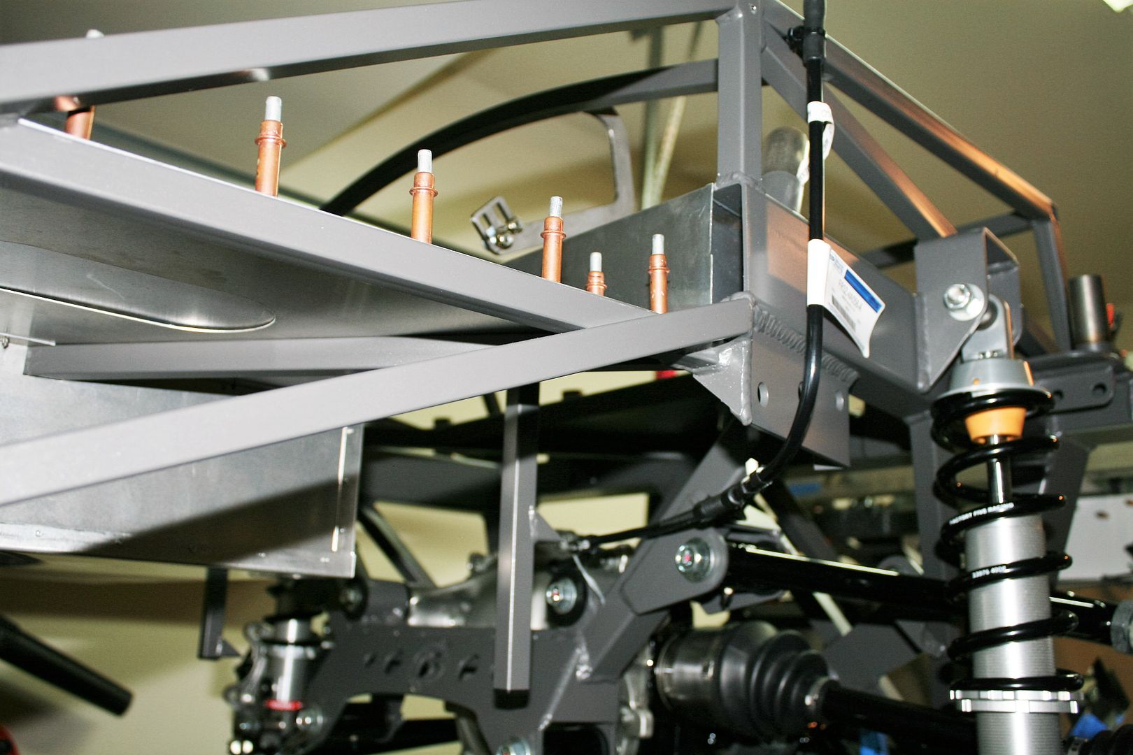
    Ok, so finally to the actual IRS assembly update. Last week I received my upper and lower control arms. I was still missing a few of the bolts, but was able to assemble everything into the chassis using some temporary hardware in a couple places. Everything works, and it turned out great. But a couple things I learned and offer as recommendations. I’ve tried it both ways, and have decided I like to grease these large poly bushing/sleeved joints BEFORE assembly. Once the joint fills with grease and squirts out around the little holes between the bushing and the sleeve, I’m now 100% sure they’re properly lubed. I smear that little extra grease on the bushing end, and it makes it way easier to assemble. For the most part, everything fits really tight. Some adjustment of the tabs might be necessary before anything will go in. I have a big Ford wrench (how many know what that is?) I got from my grandfather that works great for adjusting the mounting tabs. A big adjustable (Crescent) wrench also works. Just make sure the jaws are clean and tight before applying any pressure. Then you won't damage or mark the powder coat. I found the upper control arms especially tight to get in place. A dead blow hammer doesn’t hurt sometimes either. I found those tapered pins I made to install the center section, mentioned in an earlier update, work GREAT for helping to line up pieces as they were getting close. Drive the taper through, everything centers, and then the bolt almost pushes in. I’m saving those things. Also had to adjust the lengths slightly on a few of the supplied sleeves. All pretty normal stuff. I followed the assembly sequence exactly as described in the instructions, and torqued when they said to. The CV axles also went in just the way the instructions said. It took a little bit of a bump with the dead blow to get the inner retaining ring to click into place. Today I received the last pieces of hardware, so installed those and final torqued and marked everything. The only thing remaining is the axle nut. I ran it down with my puny air impact wrench. But I won’t be able to get the final tightness until I have some brakes or the drivetrain installed to hold it. I did make one very small change. When I installed the rear sway bar, the two threaded together rod ends were at a pretty sharp angle vs. straight up and down when the suspension was level. So I trimmed the one longer bushing by 1/8 inch, and added another 1/8 spacer on the other side. Much better. It’s not very much. Maybe just the tolerance of the bends in the sway bar.

    I’ve had a couple questions about the two lower cross-axis joints in the Mustang knuckles. They are not replaced, but used as is. The main joint (the rear one) fully pivots and turns. Like a Heim joint. It appears to be a heavy duty and well made piece. The toe arm joint (the front one) is some type of elastomer, and just flexes once bolted down. It’s pretty large and flexible. The instructions clearly state to torque the bolt down with the suspension in the level position. Makes sense. You can feel some resistance from the joint when moving the suspension up and down. The top joint is the bolted in large rod end showing in the pictures, which comes with the kit. Hope this all makes sense. I’m learning about this stuff for the first time.

    So here are some pics. Really not much else to say. I think it turned out great and looks really good. Looks an awful lot like what we saw at Factory Five during the open house. But makes a difference when it’s really your car. Everything turns nice and smooth. Just need to remember to add fluid at some point.

    Passenger side from rear. Note in all the pictures the suspension is drooping, as it would with the chassis on the lift. The final position is the upper control arm and CV axles level, and the lower control arm pointed slightly down. Note also I haven’t done anything with alignment yet.


    Passenger side from front. Note the large adjuster for camber. The toe adjustment is a little harder to see on the inner part of the lowest arm. Note none of these have to be disassembled for adjustment. Just loosen the jam nuts and adjust in place.


    Driver’s side from rear. Looks kind of like the passenger side.


    Entire IRS from back.


    Looking up.


    Closer look at the passenger side from the bottom. Can see the toe arm adjustment a little better here.


    Well that’s it. Pretty cool. Tomorrow I’m going to be finalizing my Coyote engine order. That’s next up.
    Last edited by edwardb; 10-26-2015 at 08:00 AM.
    Build 1: Mk3 Roadster #5125. Sold 11/08/2014. Build 2: Mk4 Roadster #7750. Sold 04/10/2017. Build Thread
    Build 3: Mk4 Roadster 20th Anniversary #8674. Sold 09/07/2020. Build Thread and Video. Build 4: Gen 3 Type 65 Coupe #59. Gen 3 Coyote. Legal 03/04/2020. Build Thread and Video
    Build 5: 35 Hot Rod Truck #138. LS3 and 4L65E auto. Rcvd 01/05/2021. Legal 04/20/2023. Build Thread. Sold 11/9/2023.

  18. #58

    Join Date
    Jun 2015
    Location
    Parker, TX
    Posts
    288
    Post Thanks / Like
    Great progress! I'm not sure how you are going to drag this out over 2 years now that you have all the parts...

  19. #59
    Administrator David Hodgkins's Avatar
    Join Date
    Feb 2011
    Location
    Corona del Mar, CA
    Posts
    6,135
    Post Thanks / Like
    Blog Entries
    7
    I agree, great progress. You're really blazing the trail with the new IRS. Can't wait to follow your Coyote install.


    FFR 5369 Pin Drive, IRS, Trigos, Torsen, Wilwoods, FMS BOSS 302 "B" cam , Mass-flo. CA SB100 (SPCN) Registered
    Delivered 4/23/06. "Finished" 4/2012 (still not done!)


  20. #60
    Senior Member edwardb's Avatar
    Join Date
    Feb 2011
    Location
    Lake Orion, Michigan
    Posts
    10,857
    Post Thanks / Like

    Coyote in the House

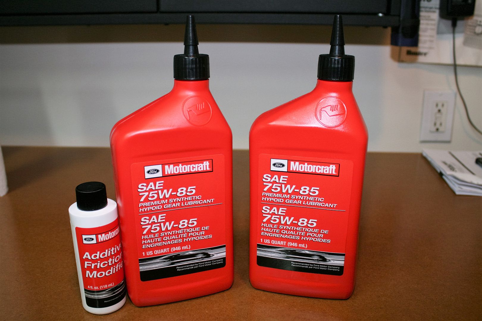
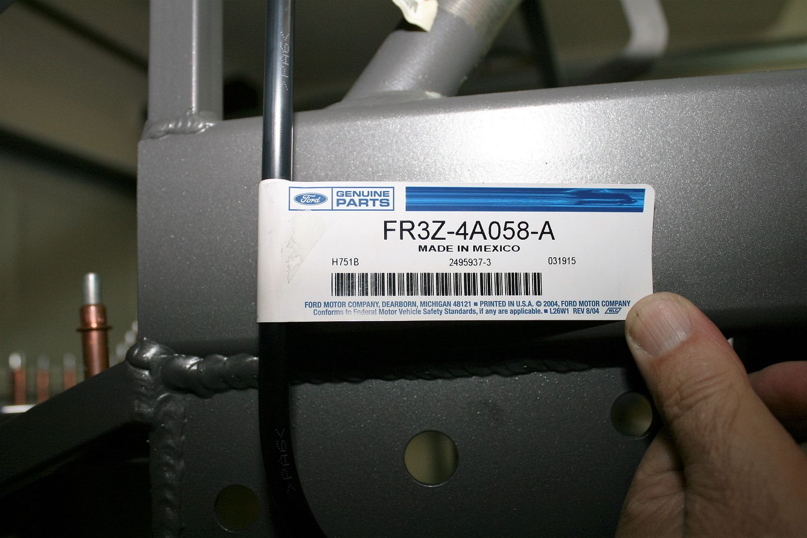
    I’ve now received my Coyote engine, so lots to share there. But first a bit of unfinished business on the IRS. I know there are many options, but I chose to fill with the exact Ford recommended gear lube and friction modifier. Didn’t see the Motorcraft products on the shelf at any of my local parts stores, so stopped at the local Ford dealer. He said they don’t normally stock the 75W-85 weight. I mentioned that was specified by Ford for the 2015 Mustang IRS, and he responded they haven’t replaced the gear lube in too many of those yet. OK I guess… Anyway, he ordered what I needed. At the same time, I ordered the Mustang vent tube for the center section. How to handle the vent isn’t mentioned anywhere in the FF instructions. The Mustang piece is maybe a little too long, but has the right size right angle connecter to plug onto the center section, and then a plastic vent at the other end, similar to the metal vent used on the 8.8 solid axle I’m familiar with. Once the stuff arrived, I put the first quart of gear lube in, then the 3+ ounces of friction modifier, and then topped off ending up using about 3.3 pints as specified. Once again I was reminded how much that friction modifier stinks! (My wife noticed very quickly as well.) Took about a day for the garage to air out.

    These are the products recommended by Ford. Easy enough to find in Mustang specs. Also listed at the end of the FF IRS instructions.


    This is the Ford part number for the Mustang vent tube assembly. It’s only $10-12.


    Just mocking up how it might be used, this is plugged onto the center section and routed over to the PS.


    I’m thinking of tie-wrapping it to the fuel tank vent tube that will come up in this same area in the wheel well. That’s where the Mustang routes it. Would be easy to shorten.


    OK, now to the Coyote adventure. Some months ago when I planned and budgeted this build, using FF’s Coyote instructions, other build threads, etc. I planned all the parts necessary, including of course the engine itself. I had several sources in mind to buy it from, mainly shopping price to be honest. When I was ready to click the button to purchase last week, the first place I went said “Ford Coyote M-6007-M50 no longer available, replaced with M-6007-M50A.” Went to a number of sites and found the same message, although some with the M-6007-M50 still available in limited quantities. Turned out what I was seeing, and I guess I must be living under a rock, is that Ford made some pretty significant changes starting in 2015, and M-6007-M50A is the 2015-2016 Coyote motor. I immediately noted it has more HP and torque, so no complaints there. Then I found they have released a brand new control pack M-6017-504V for the 2015-2016 engine, which is mandatory. The 2011-2014 engine won’t work with the new control pack and the 2015-2016 won’t work the old control pack.

    So, after all said and done, I found a great price for the 2015-2016 engine, control pack, engine covers, alternator and starter package, including free lift gate home delivery, and placed my order last Thursday. After a little back and forth discussion, received notice that it shipped on Friday. Monday it was at the freight company, and Tuesday morning it was in my garage. Now that’s service! Turns out (and I didn’t know any of this) Coyotes are made in Ford’s Essex engine plant, which is right across the river from me in Windsor, Canada. Goes from there to the Ford Racing distribution center in Livonia, MI, also pretty close to me. So it never had very far to go. BTW, the place I bought the engine is not a forum vendor, but I recommend them. They were very interested in my project, patiently made sure I had exactly what I needed, and asked me to send a picture when it’s done. Cool! PM me if you want more details.

    Just a few words about the 2015-2016 Coyote engine. I am far from a Coyote expert. I’m learning as I go here. It’s rated at 430 HP and just over 400 torque. In the Roadster with the revised intake and straight tube headers, should get a good bump from those numbers. I think it will be enough. Some of the changes to the 2015-2016 engine are bigger heads and valves. Apparently similar to the Boss heads but in cast form. A revised crankshaft, connecting rods, pistons, and a couple internal changes to the block. A major addition is charge motion control valves (CMCV) added to the intake manifold. This was something used before on 3V mod motors, as I understand, and one of the first performance modifications was to remove them. Ford claims these were done right on the Coyote, and get totally out of the way when open. They are supposed to provide better low-end torque without affecting high rpm power. I understand this also allowed some changes in how the variable cam timing works. All interesting stuff (I guess) but I think it’s cool my anniversary edition with the latest 2015 Mustang IRS now will also have the latest Mustang powerplant. The flip side is what might be the implications of the change as I go down a path not travelled yet for these builds (that I know of). I’ll detail what I’ve found out so far. Mostly OK (I think…).

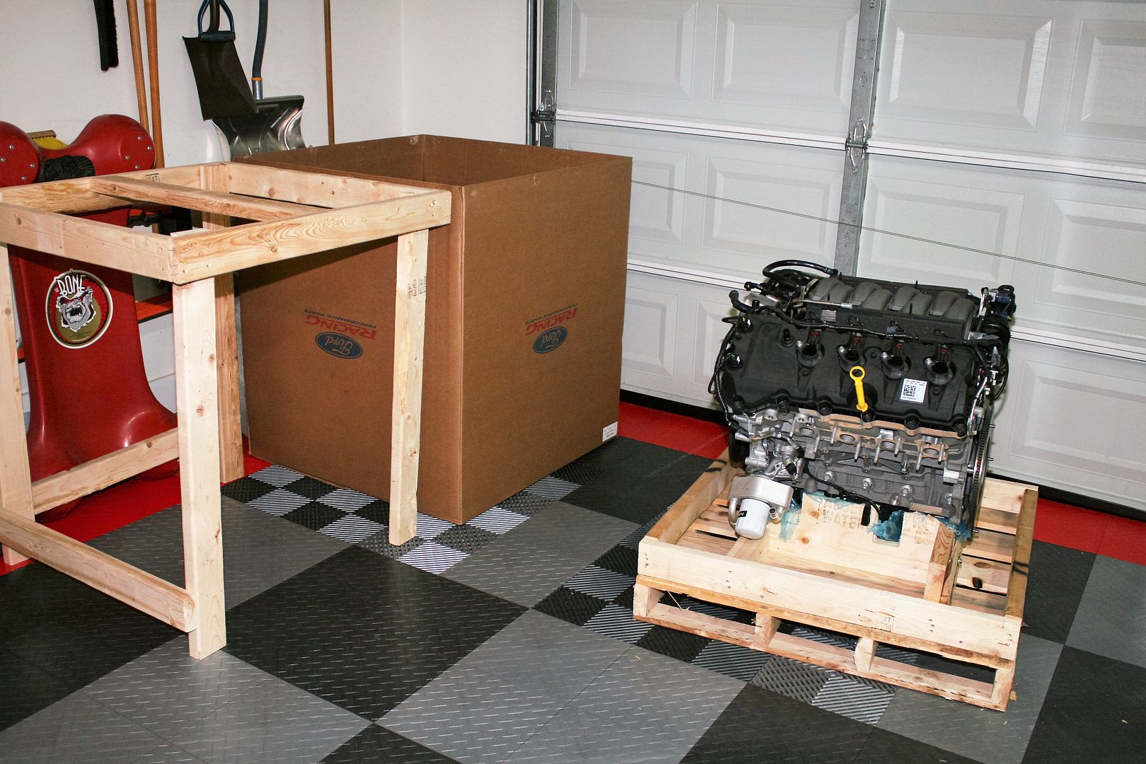
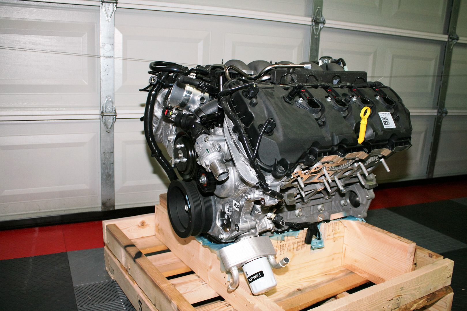
    The engine arrived crated and boxed as many have seen. First time for me seeing a Coyote outside of an engine compartment. Interesting. And HUGE.


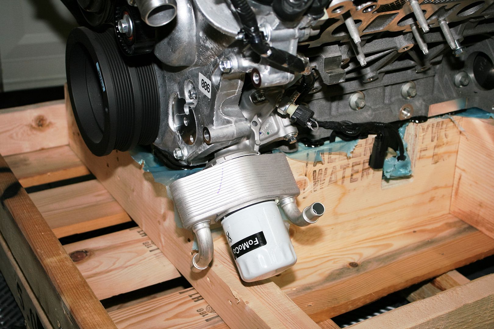
    Right off the bat, noticed they added an oil cooler to the oil filter location. After checking with some other builders, confirmed there’s no way this will fit. Good news is that it was easily removed. It’s just sitting on top of the normal oil filter location with an extended adapter hold it in place. Side note: It’s a $300+ dollar part! I’m taking a run at eBay to see if the Mustang crowd will take it off my hands.

    Build 1: Mk3 Roadster #5125. Sold 11/08/2014. Build 2: Mk4 Roadster #7750. Sold 04/10/2017. Build Thread
    Build 3: Mk4 Roadster 20th Anniversary #8674. Sold 09/07/2020. Build Thread and Video. Build 4: Gen 3 Type 65 Coupe #59. Gen 3 Coyote. Legal 03/04/2020. Build Thread and Video
    Build 5: 35 Hot Rod Truck #138. LS3 and 4L65E auto. Rcvd 01/05/2021. Legal 04/20/2023. Build Thread. Sold 11/9/2023.

  21. #61
    Senior Member edwardb's Avatar
    Join Date
    Feb 2011
    Location
    Lake Orion, Michigan
    Posts
    10,857
    Post Thanks / Like

    Coyote in the House (continued)

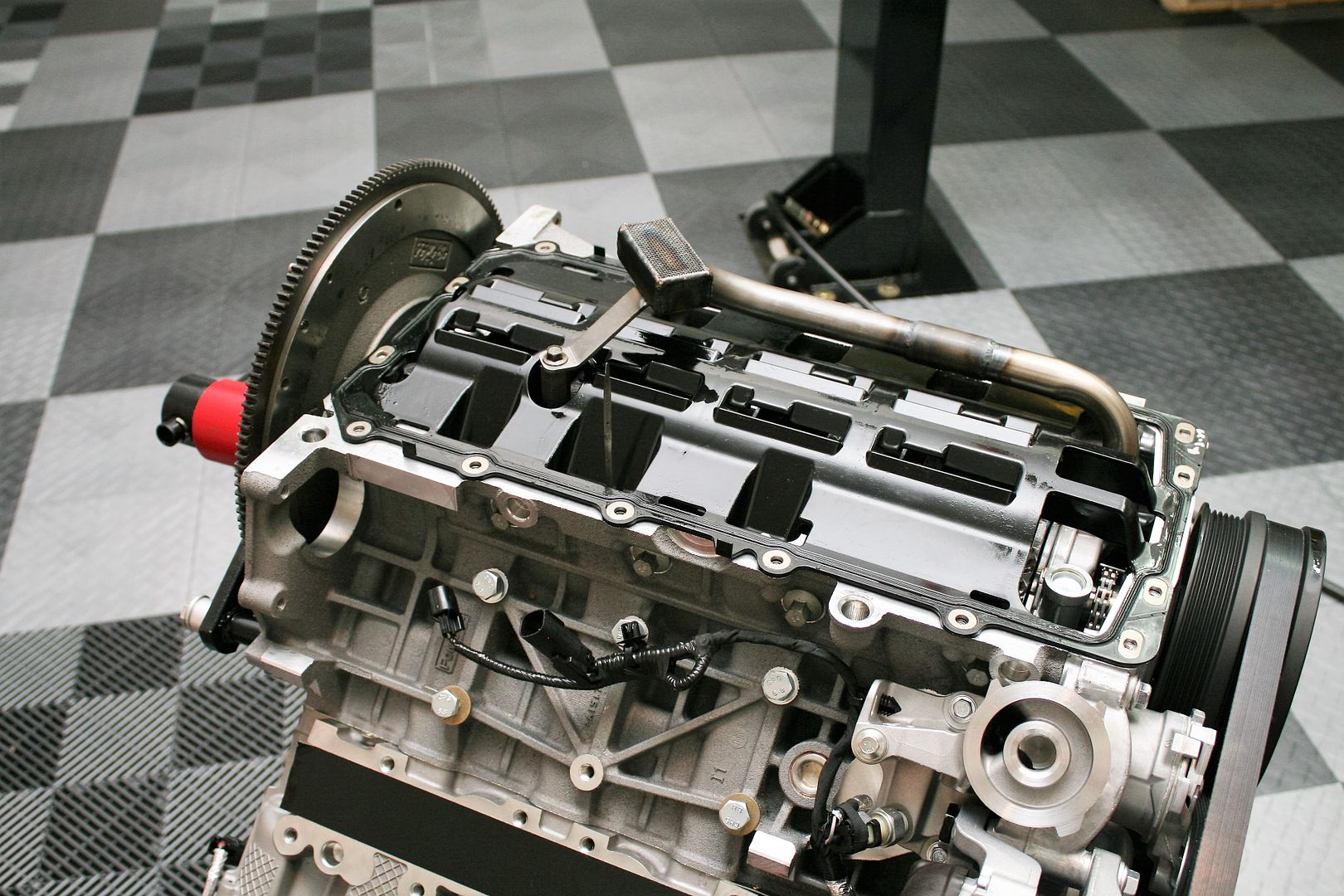
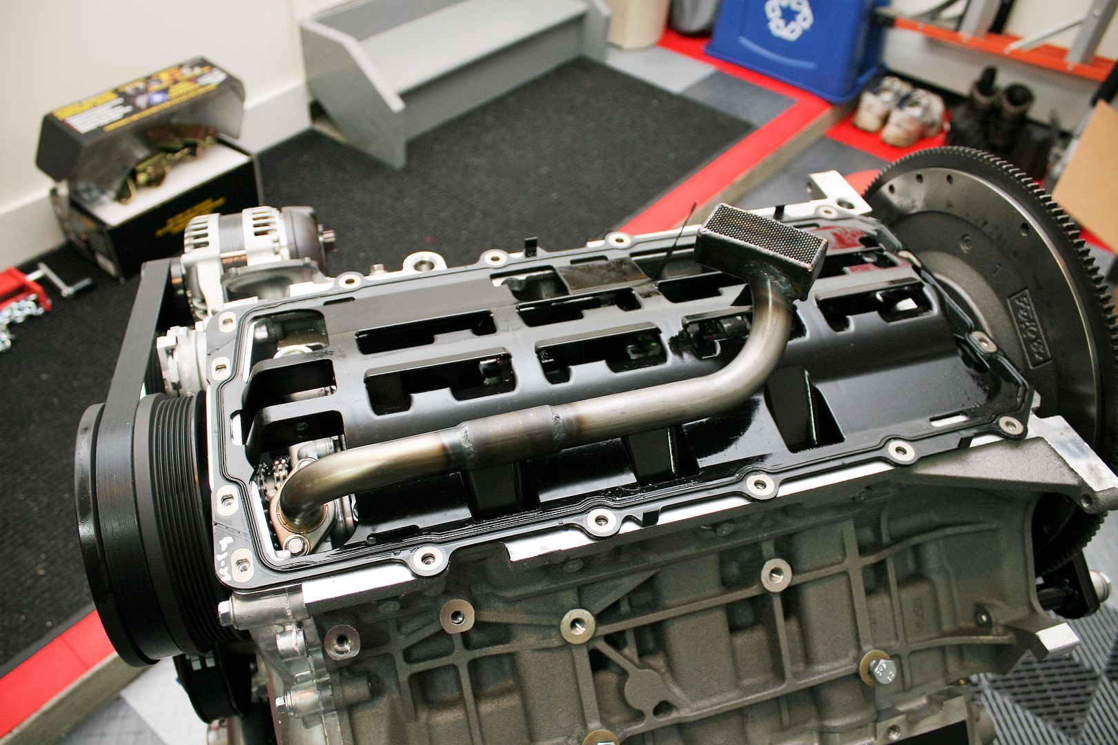
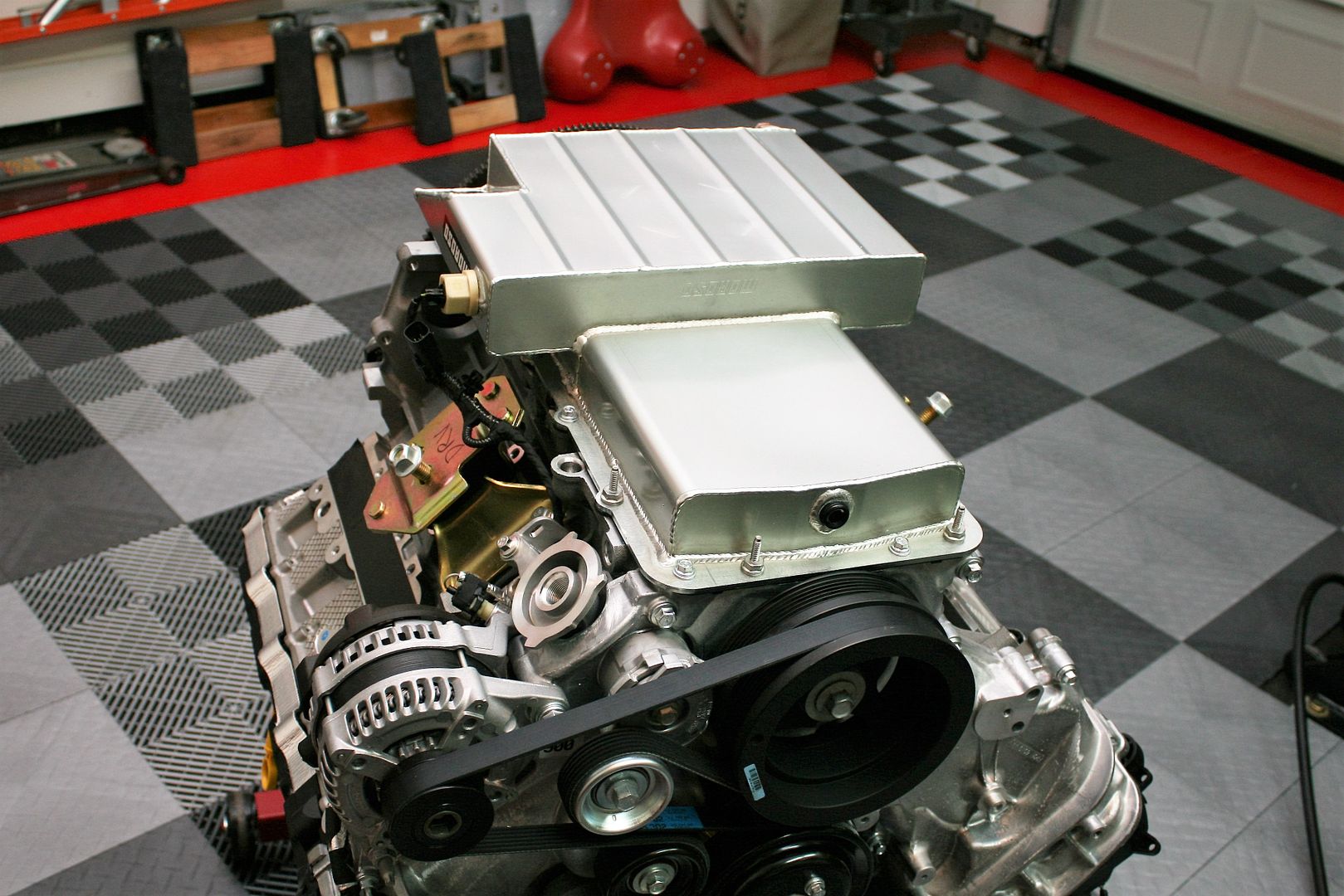
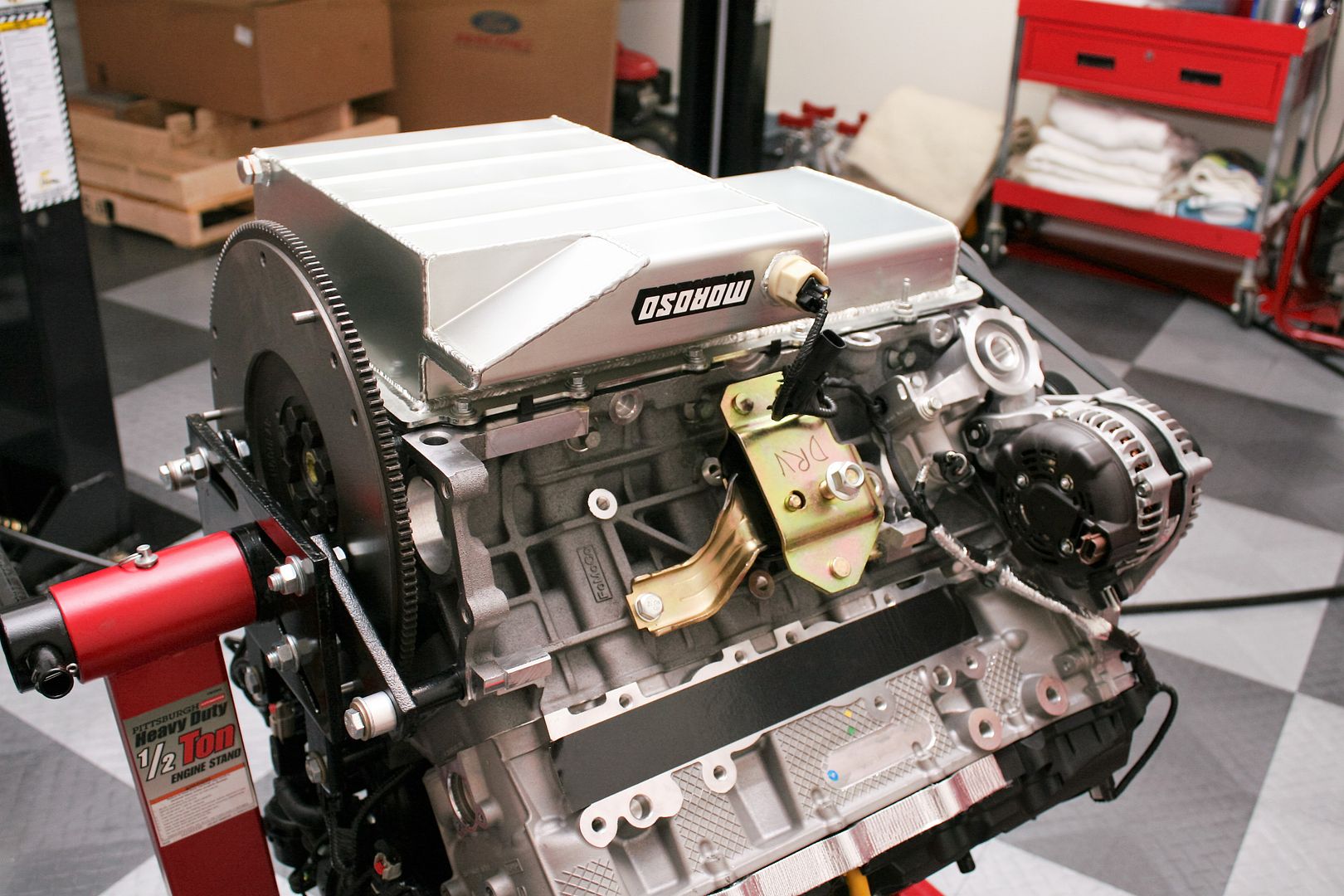
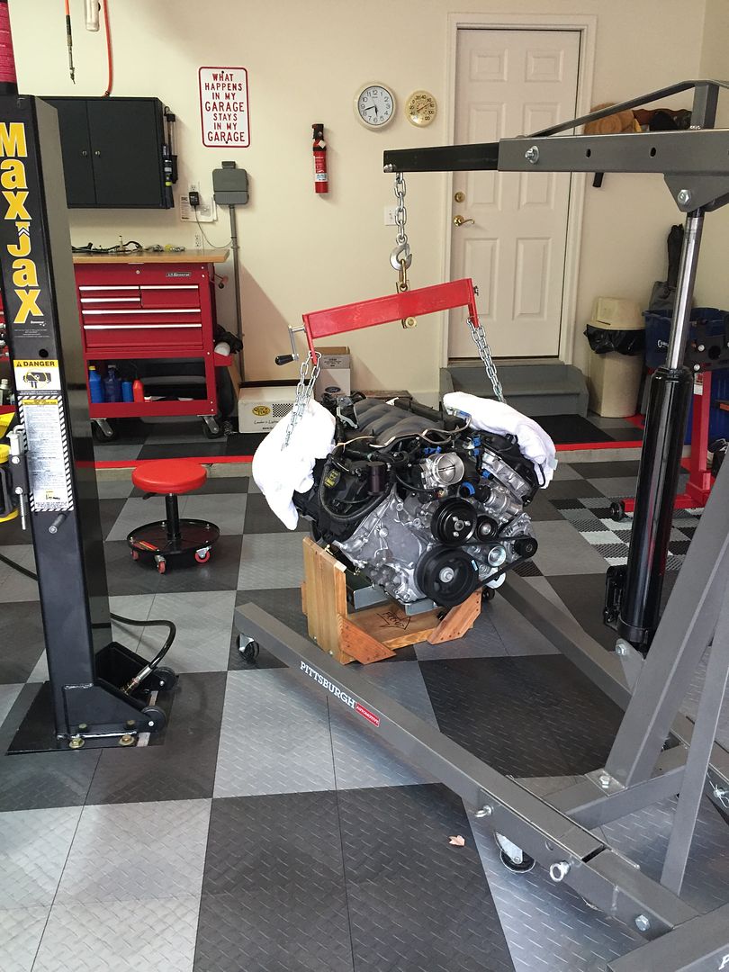
    Next order of business was to get it out of the crate and up onto the engine stand. But before I did I quickly checked the fitment of my just received Quicktime bell housing. Oops! Ordered the wrong one. Good grief. Ordered RM-6060 instead of RM-6080. I amaze myself sometimes, and not in a good way. Exchange underway. I used the side motor mount bolt locations with chains and lots of towels and rags over the engine to hook it up and onto the engine stand. Had to get some metric bolts for the back of the block long enough for the stand, so yet another visit to my friends at Ace. But it mounted up OK. Just barely fit around the flywheel. It comes filled with oil, so drained that out. I didn’t have any clean containers, so never really thought to save the oil. I should have! I didn’t know it was 8 quarts and that it was synthetic. Put some bucks into the old oil recycle there. Oh well. Yet another lesson learned. I installed the alternator using the supplied Ford Racing kit. Very easy except the one idler wheel they provide but don't show in the instructions. Guessed it needed to replace the one already on the engine, and turns out that was right. Then turned it over and took the stock pan and pickup off and replaced with the Moroso pieces.


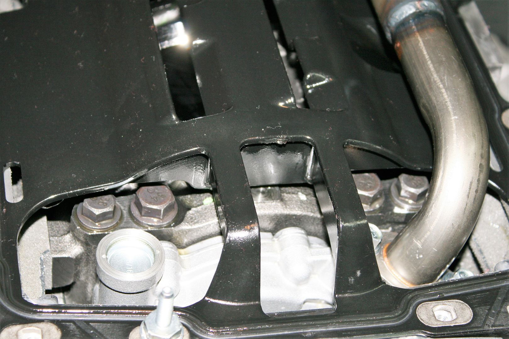
    I would have loved to lift off that factory gasket/windage tray and peak into the innards there a little. But it was stuck in place with sealant, and I chose not to disturb it. I could see the 4-bolt mains, with the front one pretty visible. Actually I guess 6-bolt if you include the ones through the side of the block. All five are just like this. Pretty stout engine there.


    After checking the pickup to pan distance using the clay method (actually plumber’s putty…) and finding it just over 3/8 inch (good) I installed the Moroso pan. Also added the engine mounts, just finger tight.


    Last thing for now with the engine, I went through the Factory Five Coyote instructions and tried to verify every connection, hose, etc. Posted a forum thread, and received some good feedback. All is accounted for except two extra vacuum hoses by the throttle body. Thanks to another forum member, determined the one on the PS is for the power brakes booster, so I will remove and use that vacuum source for the fuel regulator. The one on the other side is for the already mentioned CMCV system. This will require a connection to the Spectre intake tube.

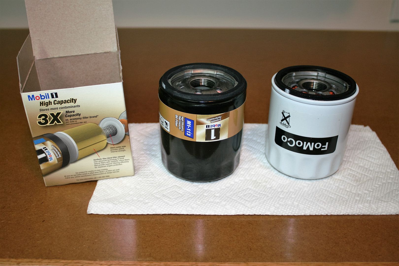
    One aside comment. Some chatter on the forums about the necessity to use the remote oil filter setup. Many have avoided doing this by using a lower profile oil filter in the stock engine location, which is what I was planning. Some though didn’t like the reduced filter size/capacity as a result. I went ahead and picked up one of the recommended lower profile filters, an M1-113. Once home, I compared it to the OEM C336B filter I removed from the engine as received from the factory. Guess what? Same size. Looks like Ford had to reduce the size of the filter due to the oil cooler noted earlier? Also suggests this smaller filter should be fine. No remote oil filter for my build.


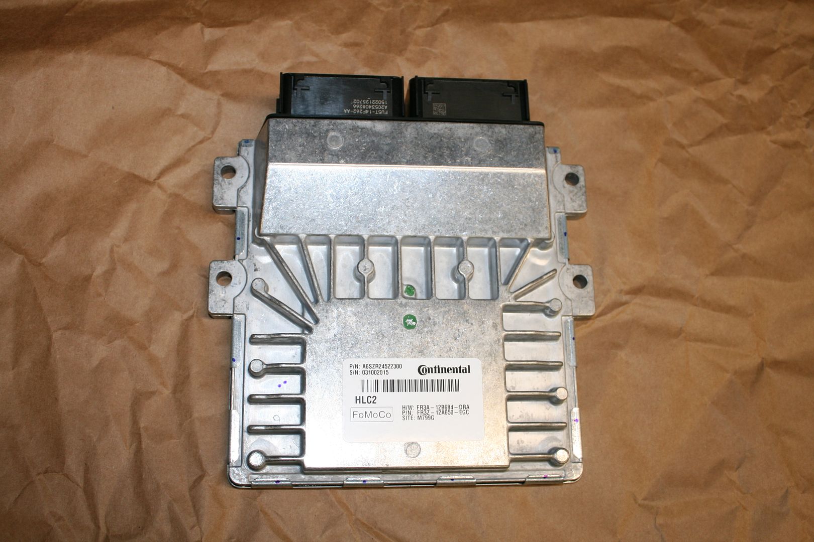
    To wrap up, while I haven’t done much with it yet, here are some observations and pictures of the new control pack. First some obvious differences. The old control pack had the O2 connections on the supplied harness. The new engine has them integrated into the engine harness. (Even though the O2 sensors they provided don’t fit into the engine connectors. Open topic with Ford Racing technical support. Looks like they provided the rear sensors instead of the front ones. Same thing I guess but obviously different connectors.) Old harness has an electronic power steering connection, the new one doesn’t. No problem for our builds. New harness has A/C connections (not needed for my build) and clutch bottom and clutch top switches. More about that later. The new control pack has a brand new PCM and power distribution box. Both completely different than the old ones. The new control pack has a fault indicator light for the dash, I assume similar to a check engine light. Tells you a fault has occurred and you need to read the codes. Ford Racing tech told me the new control pack does NOT need the speed dial like the previous version. We’ll see I guess. Finally, and this one I’m a little upset/surprised about, the new control pack doesn’t have a tach connection. (!!) When I asked Ford Racing technical about this, he listed off all the stuff the new system has that weren’t in the old one. OK, but how you could miss this? He mentioned using an Autometer tach adapter. Don’t know about that. Looking at the Speedhut gauge instructions, looks like not too big a deal to tap into one of the wires on the coil-on-plug connectors and calibrate to that. To be continued.

    OK, here are some pics: This is the new PCM. According to Ford, this is a “next generation” from the previous one, and a completely new operating system and program. Bet the tuner crowd likes that. It’s much smaller and lighter than the previous version, but looks like it will need to be mounted in a similar location based on the lengths of the supplied harness. A little interesting for me, I kind of recognize that supplier name on the PCM. I also recognize the codes and know this was manufactured in a plant in Seguin, Texas where I spent a lot of time. Yep, the company I retired from.

    Build 1: Mk3 Roadster #5125. Sold 11/08/2014. Build 2: Mk4 Roadster #7750. Sold 04/10/2017. Build Thread
    Build 3: Mk4 Roadster 20th Anniversary #8674. Sold 09/07/2020. Build Thread and Video. Build 4: Gen 3 Type 65 Coupe #59. Gen 3 Coyote. Legal 03/04/2020. Build Thread and Video
    Build 5: 35 Hot Rod Truck #138. LS3 and 4L65E auto. Rcvd 01/05/2021. Legal 04/20/2023. Build Thread. Sold 11/9/2023.

  22. #62
    Senior Member edwardb's Avatar
    Join Date
    Feb 2011
    Location
    Lake Orion, Michigan
    Posts
    10,857
    Post Thanks / Like

    Coyote in the House (continued)

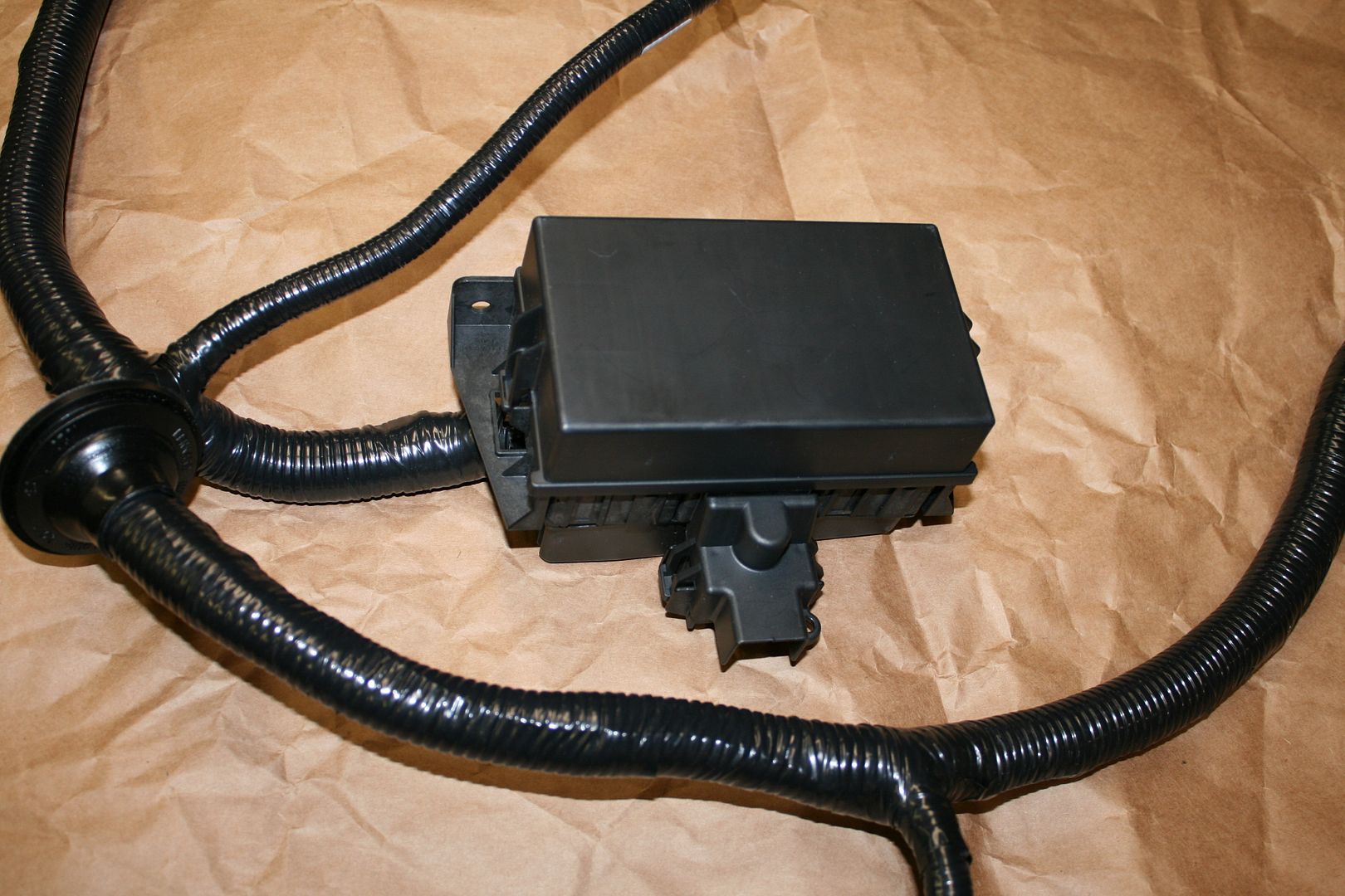
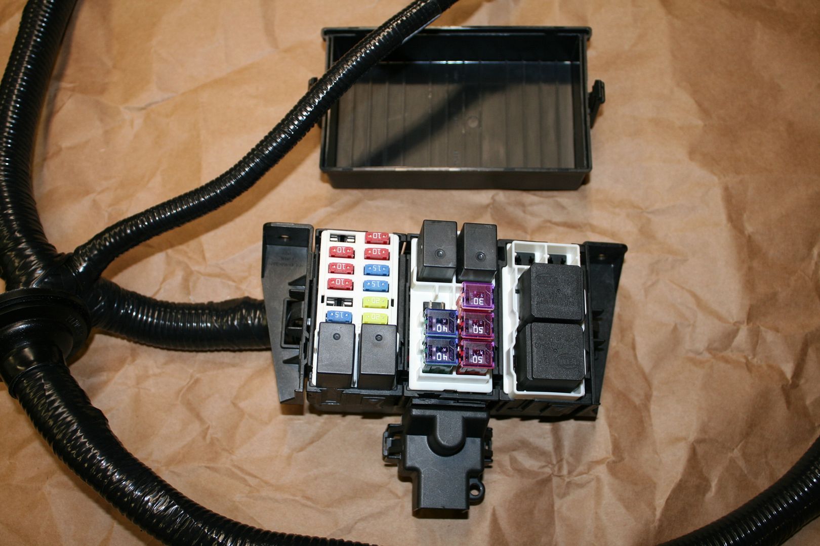
    This is the new power distribution box. Looks a lot more like something you’d see under the hood of a DD. In fact, that’s probably what it is. No wires to connect on the inside of this one like the former version.


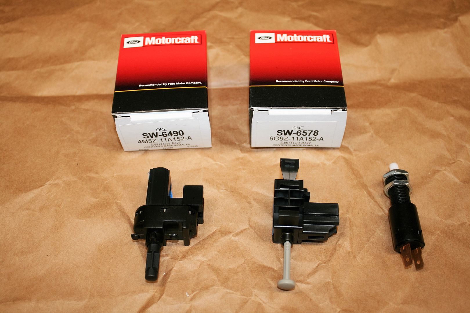
    These are the already mentioned clutch “bottom” and clutch “top” switches provided. They have dedicated legs on the harness. According to Ford Racing tech, they are mandatory. The bottom switch is required as a starter interlock. The top switch apparently triggers some reaction by the PCM to the engine when the clutch is started down. I’m not going to question them. I will install but thinking not to use these exact switches. Measuring them, they’re just 2-wire NO and NC contact switches. I’m thinking I can use the typical switches we use on our builds, like the one on the right. The top switch can be mounted in the Wilwood box just like a brake switch, and in fact I already made and installed a bracket like that on the clutch side anyway. Then just need to figure out how to have a similar switch at the bottom of the clutch stroke. Stay tuned for that as well.


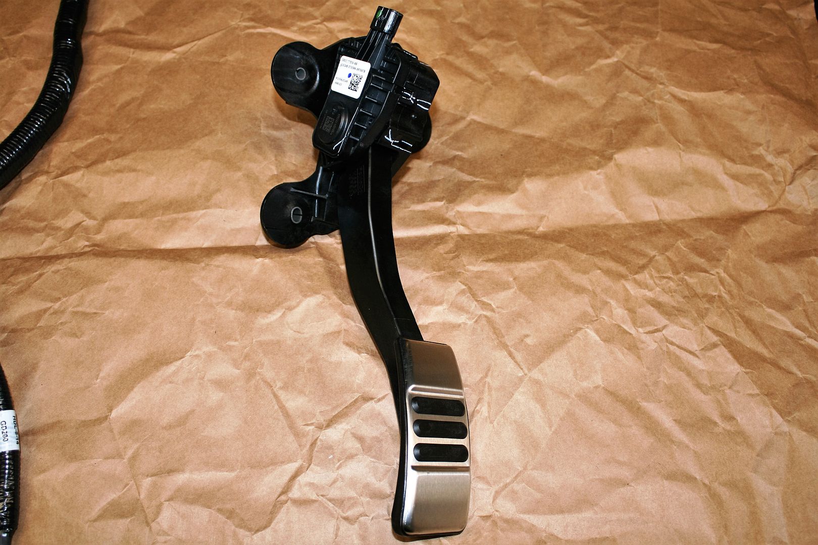
    This is the provided drive-by-wire (DBW) accelerator pedal. Same one as before. Still thinking about how I’m going to do this one. Not a fan of the way FF suggests to modify it. Lots of ideas on the forums.


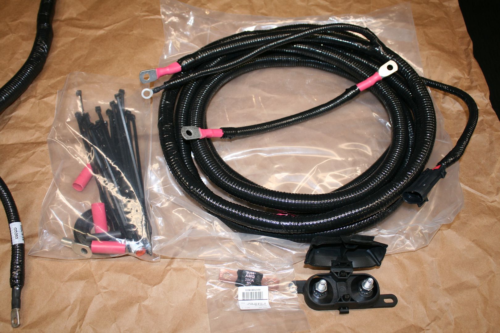
    Quite a few changes in the way power is brought into the new harness. These are the power cables provided, including an inline 250 amp fuse. The main power input to the harness is the 2-pin large Weatherpack style connector on the right side. This goes into a connector next to the power distribution box.


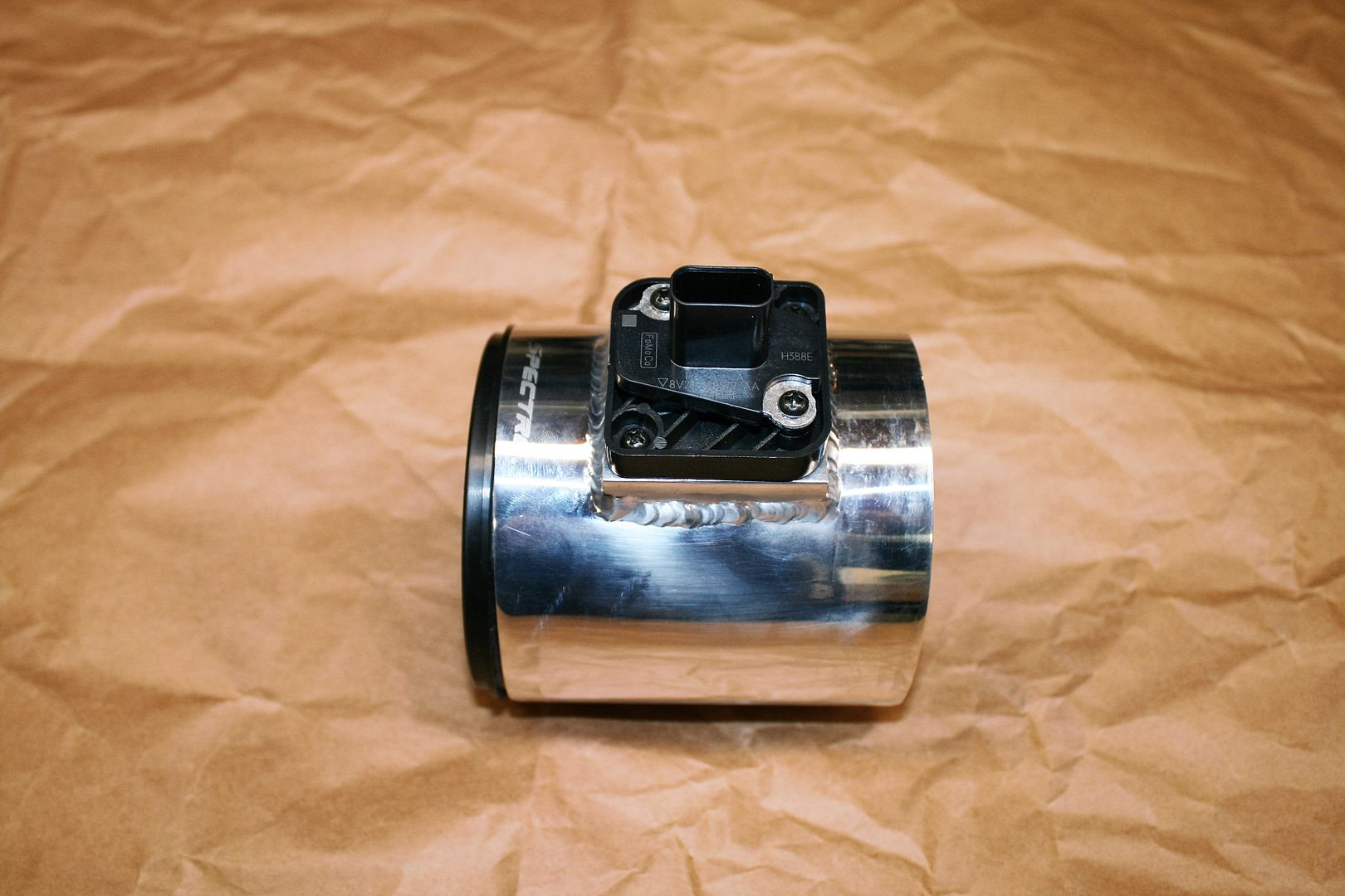
    Last but not least, no apparent change to the MAF sensor. The OEM one removes from the provided stock intake components and bolts into the recommended Spectre intake tube.


    That’s way more than enough for now. My plan is to wrap up a few more details on the engine, and then drop into the chassis. Without the transmission for now, so should be easy enough. Obviously I will need to support it accordingly. I want to mock up and confirm all the engine compartment and footbox sheet metal.
    Build 1: Mk3 Roadster #5125. Sold 11/08/2014. Build 2: Mk4 Roadster #7750. Sold 04/10/2017. Build Thread
    Build 3: Mk4 Roadster 20th Anniversary #8674. Sold 09/07/2020. Build Thread and Video. Build 4: Gen 3 Type 65 Coupe #59. Gen 3 Coyote. Legal 03/04/2020. Build Thread and Video
    Build 5: 35 Hot Rod Truck #138. LS3 and 4L65E auto. Rcvd 01/05/2021. Legal 04/20/2023. Build Thread. Sold 11/9/2023.

  23. #63
    Junior Member
    Join Date
    Jan 2015
    Posts
    21
    Post Thanks / Like
    Thanks for all of the pictures and for detailing the recent changes to the kit and other parts. You are saving a lot of people a lot of frustration!

  24. #64
    Junior Member
    Join Date
    Jul 2015
    Location
    Utah mostly
    Posts
    21
    Post Thanks / Like
    Question for you,
    Since you removed the oil cooler how are you going to mount the filter? I know with my 2014 when I installed the oil cooler it uses a longer bolt than the stock one. It looks like you have removed that longer bolt but now don't have any threads for the filter to grab on to. Have you found a replacement yet? you might want to look at the 2011-2014 version... in fact mine might be lying around somewhere, right next to the stock lower radiator hose sitting in the garage. let me know if you want either!

  25. #65
    Senior Member edwardb's Avatar
    Join Date
    Feb 2011
    Location
    Lake Orion, Michigan
    Posts
    10,857
    Post Thanks / Like
    Quote Originally Posted by ticopow View Post
    Question for you,
    Since you removed the oil cooler how are you going to mount the filter? I know with my 2014 when I installed the oil cooler it uses a longer bolt than the stock one. It looks like you have removed that longer bolt but now don't have any threads for the filter to grab on to. Have you found a replacement yet? you might want to look at the 2011-2014 version... in fact mine might be lying around somewhere, right next to the stock lower radiator hose sitting in the garage. let me know if you want either!
    Good question. Never know how much detail to include. I've got it covered I think. I ordered the normal short oil filter adapter along with a couple other parts from Tasca Ford a couple days ago. Supposed to be delivered on Monday. I'm planning to use a Breeze lower radiator hose. But thanks for the offers!
    Build 1: Mk3 Roadster #5125. Sold 11/08/2014. Build 2: Mk4 Roadster #7750. Sold 04/10/2017. Build Thread
    Build 3: Mk4 Roadster 20th Anniversary #8674. Sold 09/07/2020. Build Thread and Video. Build 4: Gen 3 Type 65 Coupe #59. Gen 3 Coyote. Legal 03/04/2020. Build Thread and Video
    Build 5: 35 Hot Rod Truck #138. LS3 and 4L65E auto. Rcvd 01/05/2021. Legal 04/20/2023. Build Thread. Sold 11/9/2023.

  26. #66
    Junior Member
    Join Date
    Jul 2015
    Location
    Utah mostly
    Posts
    21
    Post Thanks / Like
    I figured they were just collecting dust here. Looks like a great build, and I think you will enjoy the 2015 motor a lot more. They can take a lot more punisment than the 2011-14 version can. with a SC mine can do about 600 rwhp, your motor can do 700 if not more with the same reliability! Not saying you will throw a blower on it, but it's definitely an option

  27. #67
    2bking's Avatar
    Join Date
    Jul 2013
    Location
    Garland, Texas
    Posts
    799
    Post Thanks / Like
    I noticed the sensor mounted in the Moroso oil pan. I think it's the low oil level sender but the earlier PCMs didn't support it. It was one of the many items removed from the PCM along with the oil pressure monitor. I rethreaded the plastic part to accept the oil temperature sender. Be careful on the first trial fit of the engine because this part is very close to the 4" tube and engine mount.
    King
    Roadster #8127, ordered 7/12/13, received 9/11/13
    http://thefactoryfiveforum.com/showt...4-Coyote-Build

  28. #68
    Senior Member edwardb's Avatar
    Join Date
    Feb 2011
    Location
    Lake Orion, Michigan
    Posts
    10,857
    Post Thanks / Like
    Quote Originally Posted by 2bking View Post
    I noticed the sensor mounted in the Moroso oil pan. I think it's the low oil level sender but the earlier PCMs didn't support it. It was one of the many items removed from the PCM along with the oil pressure monitor. I rethreaded the plastic part to accept the oil temperature sender. Be careful on the first trial fit of the engine because this part is very close to the 4" tube and engine mount.
    Thanks for the tip. Yes, that is the low oil sensor and I have no idea whether it's supported in the new PCM or not. Something I will check on with Ford Racing, after they answer a couple more important questions. I'll definitely keep an eye on it during my first engine mockup.
    Build 1: Mk3 Roadster #5125. Sold 11/08/2014. Build 2: Mk4 Roadster #7750. Sold 04/10/2017. Build Thread
    Build 3: Mk4 Roadster 20th Anniversary #8674. Sold 09/07/2020. Build Thread and Video. Build 4: Gen 3 Type 65 Coupe #59. Gen 3 Coyote. Legal 03/04/2020. Build Thread and Video
    Build 5: 35 Hot Rod Truck #138. LS3 and 4L65E auto. Rcvd 01/05/2021. Legal 04/20/2023. Build Thread. Sold 11/9/2023.

  29. #69
    Senior Member edwardb's Avatar
    Join Date
    Feb 2011
    Location
    Lake Orion, Michigan
    Posts
    10,857
    Post Thanks / Like

    My Take on the Coyote Accelerator Pedal

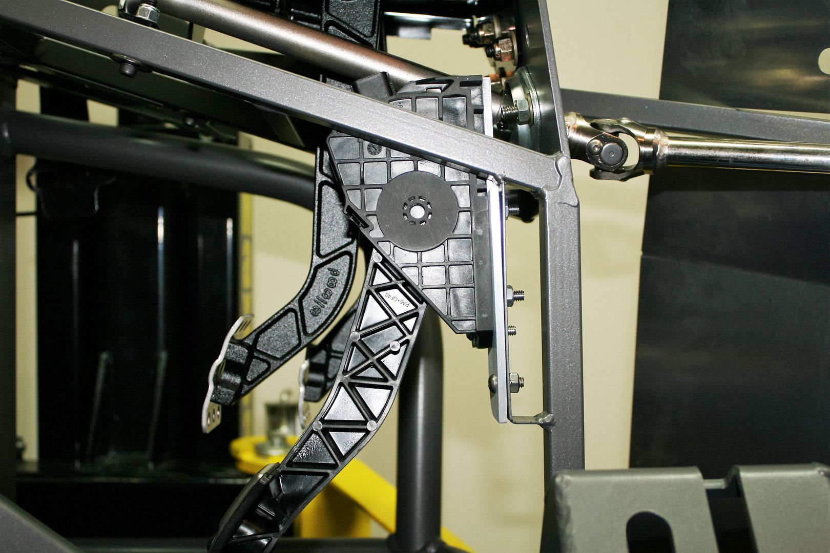
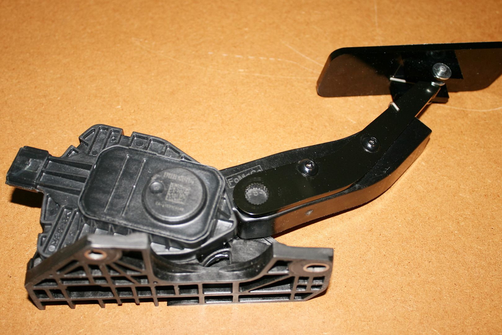
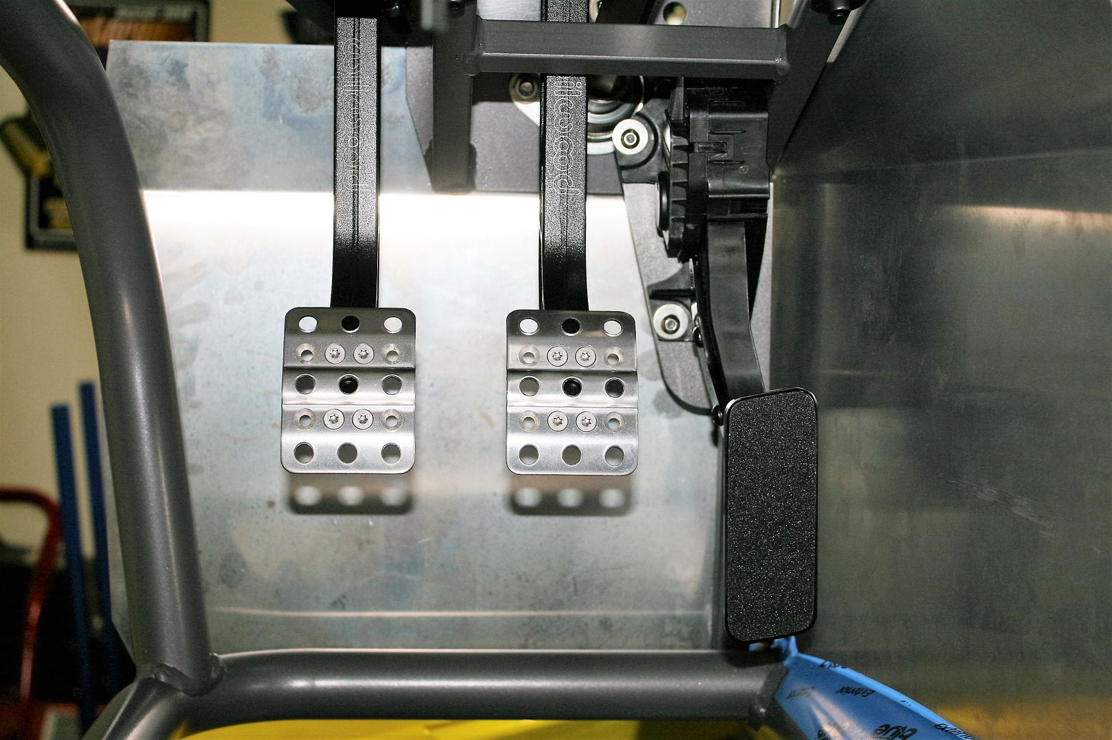
    Like many modern EFI engines, the Coyote is a Drive-By-Wire (DBW) setup, meaning no physical connection to the engine. Accelerator pedal movements send a signal to the engine computer, which in turn uses an electric motor on the throttle body to open/close the valve. The Coyote crate motor includes the required DBW accelerator pedal. It’s large and a little clunky, and requires some level of modification to fit. Factory Five includes a multi-page set of instructions for modifying the provided piece, which many have done successfully. But some, including me, find it a little crude. There are a couple alternatives. Use the existing pedal maybe improving a little on the mods. Use a similar module from a 2014 Ford Van which is smaller and fits better/looks neater. Or go all in with a Lokar DBW module and pedal which several have done. Option one is basically free, e.g. I already paid for it. Option two is around $100. Option three is in the $400+ range, depending on which pedal assembly you pick. After reading every forum thread and post on the subject I could find, one of the takeaways is none of the options provide any real upgrade to how the system works. All are similar. It seems mainly about fit and appearance. So I decided to do my own take on using the already received Ford Racing pedal assembly. If I wasn’t happy with how it turned out, easy enough to look at the other options with nothing lost but my time. Which I have plenty of right now! I really like the Lokar option, and spent quite a bit of time looking at it, looking at pictures guys have posted with it installed, and generally just trying to convince myself it was a good idea. But that’s expensive, and even though this isn’t a low budget build, happy to spend the money elsewhere.

    My review of the installation guys have done with the existing pedal showed two major issues: One being appearance. The grafted on pedal and that big chunky module just don’t look very nice. Second, as installed, it shortens the overall pedal length some, resulting in higher effort and more sensitive throttle response. I don’t know if this has really been tested and compared, but makes sense if the lever arm is shorter. So I approached my install trying to address these two points. In order to not cut off the arm so much and not have the pedal too low, the overall assembly needs to be raised. The standard FF install bolts it pretty much to the existing accelerator mounting plate. Several guys have figured out how to get it mounted higher. One moved it way up and left the arm intact, which looked good, but it involved removing the FF mounting plate, and that didn’t leave me a way back if I didn’t like how it turned out. So I tried to find a happy medium.

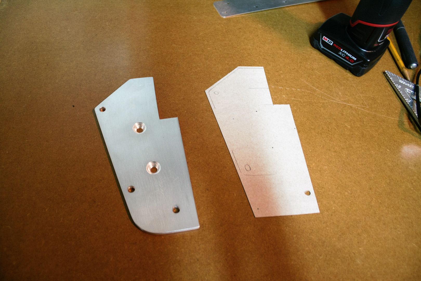
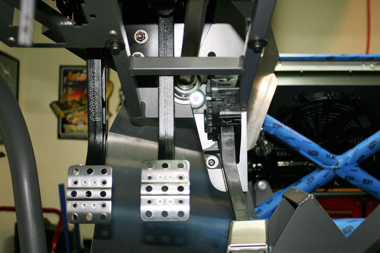
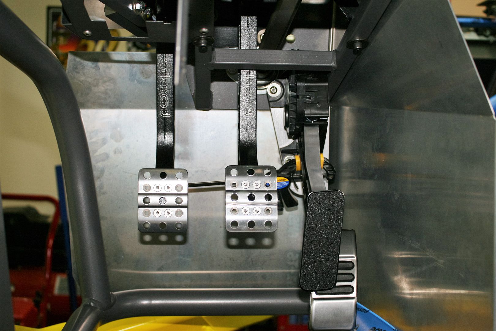
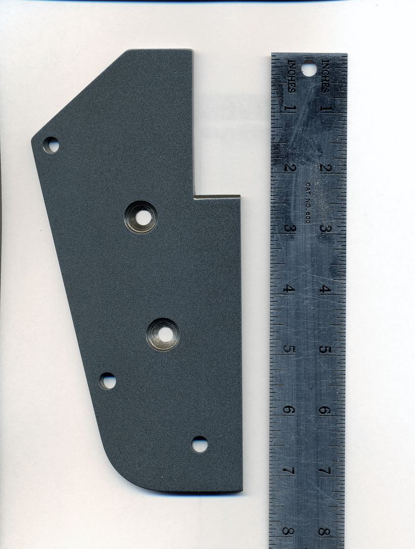
    My first step was to trim the module basically as outlined in the FF instructions. I tried to do it neat and clean so it looked like it was made that way. I also trimmed the big round pads off the outside mounting ears. They don’t add anything structural because they don’t contact on the back. Perhaps in the production cars they fit into a grommet or something. Not on our cars. With the module as small as it could be, and without the pedal cut off yet, I made a pattern using a cereal box (nothing too good for me) to move it up as high as it seemed practical. I also tried to keep it over toward the center of car as much as possible so the pedal hit where I wanted it in the footbox without the module being at a wonky angle. All was good until I found the connector location at the very top of the module was now too close to the steering column. So I removed some ribs on the side of the module where it was against the 3/4 inch tube to get it over about another 1/4 inch and all was good. Once I was happy with the template, made the real thing out of 3/16 inch aluminum plate and got the module placed where it looked pretty good. Then I took the FF supplied accelerator pedal, and using clamps, determined where it needed to be mounted on the module arm. I was looking at the length and also depth behind the brake pedal. The module placement had already pretty much determined the side-to-side location. Since I’m very satisfied with the pedal spacing on my current Mk4, I tried to duplicate those dimensions. I’m happy to say it’s very close. Note, as mentioned earlier, I didn’t have the pedal cut off yet. This was to try to address the appearance aspect. FF has you cut the arm off pretty short, leaving a stub visibly showing. My idea was to leave the arm as long as possible, and have it end behind the FF pedal itself, therefore more hidden. Also allowed me to space the mounting bolts a little further apart, which in theory is more structurally sound. So with the FF pedal location now determined, cut off the module pedal, and bolted it to the side of the module arm. Sprayed some of my (almost) matching Rust-Oleum paint on the bracket, and this morning put it all back together. I set the seat in the cockpit and checked out how it felt. All good. I think it’s a keeper. My only quibble at this point is the black non-skid surface on the FF pedal doesn’t match the other pedals that well. I may do something with that, but for now I’m leaving it as is. Here are a few pics.

    Paper template and aluminum piece after finalizing.


    First time installed.


    From the inside, showing it slightly notched around the 3/4 inch tube.


    Mocking up the FF pedal graft.


    Graft complete and bent to match the module arm. Note I didn’t cut off the end of the FF pedal arm as instructed. Looks a little better, plus this also shows my version is about 1 inch longer. Only slightly shorter than the stock version. I’m thinking (hoping) I won’t be able to tell the difference.


    Adapter plate all painted and ready to install. I threw a ruler next to it.


    All done.

    Last edited by edwardb; 02-03-2016 at 10:59 AM.
    Build 1: Mk3 Roadster #5125. Sold 11/08/2014. Build 2: Mk4 Roadster #7750. Sold 04/10/2017. Build Thread
    Build 3: Mk4 Roadster 20th Anniversary #8674. Sold 09/07/2020. Build Thread and Video. Build 4: Gen 3 Type 65 Coupe #59. Gen 3 Coyote. Legal 03/04/2020. Build Thread and Video
    Build 5: 35 Hot Rod Truck #138. LS3 and 4L65E auto. Rcvd 01/05/2021. Legal 04/20/2023. Build Thread. Sold 11/9/2023.

  30. #70
    Senior Member edwardb's Avatar
    Join Date
    Feb 2011
    Location
    Lake Orion, Michigan
    Posts
    10,857
    Post Thanks / Like

    My Take on the Coyote Accelerator Pedal (continued)

    Couple of other Coyote updates since my last post. I mentioned before about the provided O2 sensors not matching the connectors with the engine harness. I’ve been back and forth with Ford Racing tech support on this one, and after sending pictures they agreed there is a problem. They checked an engine they had, plus also with engineering, and now confirm I have the wrong sensors. They are in the process of sending replacement parts. Note the O2 sensors I received are the exact ones called out in the new control pack instructions. So hopefully they will be changing that. Also note this is one of the differences between the new version of the Coyote and the previous one. Before the O2 sensor connectors were on the provided control pack harness. Now they are already on the engine, and not on the control pack harness. This does present a little bit of a challenge. Guys were able to adjust the former harness and sometimes get the cables to reach the sensors without extensions. Not so now. The O2 sensor connections on the new engine are fixed. One at the top RH rear corner, and the other on the lower LH side right next to the oil level sensor. I’ve checked using my new stainless headers and the provided O2 sensors. Both are 6-12 inches short of reaching the O2 bung. I’ll see if the new sensors they provide are similar (expect they will be) and determine the extensions needed once I mock everything up in the chassis. But expect to require extensions in all cases with the new engine. Ford Racing tech also confirmed, again this time from engineering, that the new control pack does not have a tach connection. I’m also waiting for their best and final opinion about the speed dial question. There still seems to be some question about that. The manual transmission engine provided as a crate motor does not have a transmission connection, even though there is one showing in the instructions. Another error. So no speed sensor connection there and none through the new control pack. Doesn’t the PCM require vehicle speed? That’s my question. I don’t see now where it would get it. My build has a GPS speedometer, so I actually don’t even need the speed sensor output for the gauges. But there’s one built into the TKO, so easy enough to feed that to the engine setup if required. But still an open question.

    I’m back to doing fill-in work until my bell housing arrives. When it does, I’ll be dropping the engine into the chassis and start finalizing footbox sheet metal.
    Last edited by edwardb; 10-22-2015 at 09:44 AM.
    Build 1: Mk3 Roadster #5125. Sold 11/08/2014. Build 2: Mk4 Roadster #7750. Sold 04/10/2017. Build Thread
    Build 3: Mk4 Roadster 20th Anniversary #8674. Sold 09/07/2020. Build Thread and Video. Build 4: Gen 3 Type 65 Coupe #59. Gen 3 Coyote. Legal 03/04/2020. Build Thread and Video
    Build 5: 35 Hot Rod Truck #138. LS3 and 4L65E auto. Rcvd 01/05/2021. Legal 04/20/2023. Build Thread. Sold 11/9/2023.

  31. #71
    2bking's Avatar
    Join Date
    Jul 2013
    Location
    Garland, Texas
    Posts
    799
    Post Thanks / Like
    Nice job on the accelerator pedal. Very clean looking.

    Apparently the PCM doesn't need vehicle speed. It would be necessary for cruse control but the Ford Racing PCMs have that function dieted out. In the earlier controls pack there wasn't a speed dial sensor connection. It has to be wired into the PCM connector. Ford Racing will supply the pins if you asked but there are a few unused pins in the PCM connector that can be removed and reused to connect the speed dial. I saw a post where someone tried connecting the electronic sensor in the transmission directly to the PCM and reported that it seemed to work.
    King
    Roadster #8127, ordered 7/12/13, received 9/11/13
    http://thefactoryfiveforum.com/showt...4-Coyote-Build

  32. #72
    Senior Member edwardb's Avatar
    Join Date
    Feb 2011
    Location
    Lake Orion, Michigan
    Posts
    10,857
    Post Thanks / Like
    Quote Originally Posted by 2bking View Post
    Nice job on the accelerator pedal. Very clean looking.

    Apparently the PCM doesn't need vehicle speed. It would be necessary for cruse control but the Ford Racing PCMs have that function dieted out. In the earlier controls pack there wasn't a speed dial sensor connection. It has to be wired into the PCM connector. Ford Racing will supply the pins if you asked but there are a few unused pins in the PCM connector that can be removed and reused to connect the speed dial. I saw a post where someone tried connecting the electronic sensor in the transmission directly to the PCM and reported that it seemed to work.
    Thanks! Interesting about the PCM not needing speed and that it's dieted out of the former PCM. At this point, we can only assume the new PCM is the same. As I mentioned before, Ford Racing told me this is a completely new PCM with a new operating system and an all new engine program. This is what I posted on the other forum about the speed dial question, based on some other input: The tech at Ford Racing was pretty confident it's no longer required, just as (he claimed) it was no longer required in later versions of the previous model. I suspect some will disagree, but that's what he told me. Regardless, he's checking with engineering to get their input. It's true that when the speed dial first came out as a fix, it was necessary to break into the harness to install. The most recent version of the 2011-2014 control pack specifically advertises though that it has the wires for the speed dial already installed. But it's not mentioned anywhere in the 2015-2016 control pack instructions. Interesting.
    Build 1: Mk3 Roadster #5125. Sold 11/08/2014. Build 2: Mk4 Roadster #7750. Sold 04/10/2017. Build Thread
    Build 3: Mk4 Roadster 20th Anniversary #8674. Sold 09/07/2020. Build Thread and Video. Build 4: Gen 3 Type 65 Coupe #59. Gen 3 Coyote. Legal 03/04/2020. Build Thread and Video
    Build 5: 35 Hot Rod Truck #138. LS3 and 4L65E auto. Rcvd 01/05/2021. Legal 04/20/2023. Build Thread. Sold 11/9/2023.

  33. #73
    Junior Member
    Join Date
    Nov 2014
    Posts
    6
    Post Thanks / Like
    Alright! Like Lloyd from Dumb and Dumber said: "So you're telling me there's a chance!!"
    Congrats on your new project! Now more than ever I'm going to be buying my Lotto tickets and crossing my fingers so I can make an offer on your 7750 when the time comes!!

  34. #74
    Senior Member edwardb's Avatar
    Join Date
    Feb 2011
    Location
    Lake Orion, Michigan
    Posts
    10,857
    Post Thanks / Like
    Quote Originally Posted by blkout25 View Post
    Alright! Like Lloyd from Dumb and Dumber said: "So you're telling me there's a chance!!" Congrats on your new project! Now more than ever I'm going to be buying my Lotto tickets and crossing my fingers so I can make an offer on your 7750 when the time comes!!
    Great quote from a funny movie. I'm enjoying #7750 so much it's hard to image selling it, but that's the plan. Sadly, it's now hunkered down until spring. Several have expressed interest. If all goes according to plan, probably about a year from now.
    Last edited by edwardb; 10-23-2015 at 09:19 PM.
    Build 1: Mk3 Roadster #5125. Sold 11/08/2014. Build 2: Mk4 Roadster #7750. Sold 04/10/2017. Build Thread
    Build 3: Mk4 Roadster 20th Anniversary #8674. Sold 09/07/2020. Build Thread and Video. Build 4: Gen 3 Type 65 Coupe #59. Gen 3 Coyote. Legal 03/04/2020. Build Thread and Video
    Build 5: 35 Hot Rod Truck #138. LS3 and 4L65E auto. Rcvd 01/05/2021. Legal 04/20/2023. Build Thread. Sold 11/9/2023.

  35. #75

    Join Date
    Jun 2015
    Location
    Parker, TX
    Posts
    288
    Post Thanks / Like
    Edwardb,

    Help! I am struggling with the Rear Swaybar attach point. Did your kit come with an extra brace/attachment for the swaybar? Here is an image of the piece in question. I received the swaybars last week but no brackets came with them or that I can find on any of the packing slips.
    Rear Swaybar attach point.png

  36. #76
    Senior Member edwardb's Avatar
    Join Date
    Feb 2011
    Location
    Lake Orion, Michigan
    Posts
    10,857
    Post Thanks / Like
    Quote Originally Posted by RRussellTx View Post
    Edwardb, Help! I am struggling with the Rear Swaybar attach point. Did your kit come with an extra brace/attachment for the swaybar? Here is an image of the piece in question. I received the swaybars last week but no brackets came with them or that I can find on any of the packing slips.
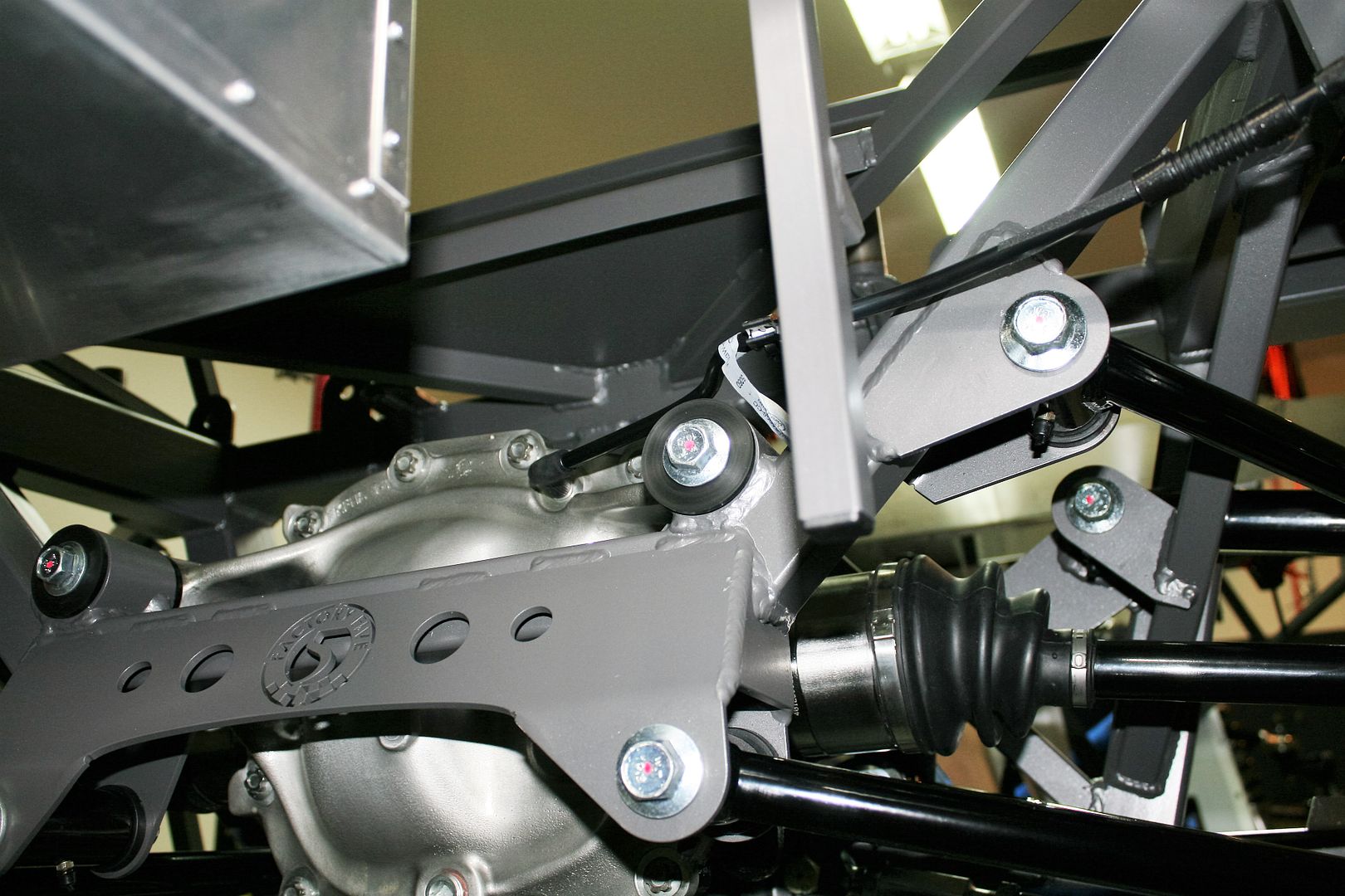
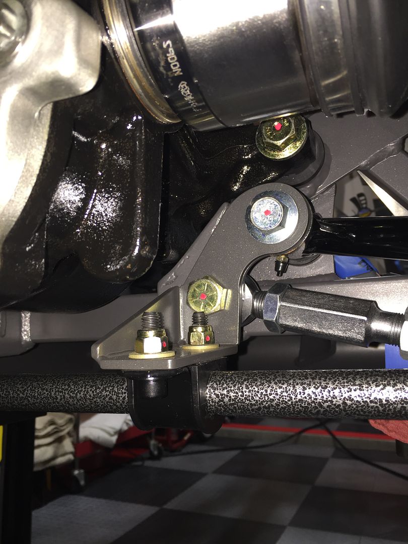
    Yes, you should have received brackets for the rear sway bar mount, part numbers 16000 and 16001. They're pretty substantial welded right angle pieces that fit under the forward LCA and toe arm bolts. Mine were on the original kit parts list, but initially backordered. They came several weeks later. Also you should have received 1/4 inch longer tow arm bolts 12384 in your rear sway bar parts bag because the regular bolts aren't quite long enough for the added thickness of the sway bar bracket. The LCA bolts are long enough as is. The added brackets are briefly mentioned in the IRS instructions, and also in the rear sway bar instructions. Here's a better picture showing the PS bracket and how it fits under the two bolts. Of course the same thing only reversed on the DS. I had it powder coated to match the chassis. Hope this answers your questions.

    Last edited by edwardb; 10-26-2015 at 08:00 AM.
    Build 1: Mk3 Roadster #5125. Sold 11/08/2014. Build 2: Mk4 Roadster #7750. Sold 04/10/2017. Build Thread
    Build 3: Mk4 Roadster 20th Anniversary #8674. Sold 09/07/2020. Build Thread and Video. Build 4: Gen 3 Type 65 Coupe #59. Gen 3 Coyote. Legal 03/04/2020. Build Thread and Video
    Build 5: 35 Hot Rod Truck #138. LS3 and 4L65E auto. Rcvd 01/05/2021. Legal 04/20/2023. Build Thread. Sold 11/9/2023.

  37. #77

    Join Date
    Jun 2015
    Location
    Parker, TX
    Posts
    288
    Post Thanks / Like
    Thanks!! That is very helpful - I received the bolt but not the bracket. Here is a pic of my packing slip:
    image.jpeg

    Looks like I need to make another call...

  38. #78
    Senior Member edwardb's Avatar
    Join Date
    Feb 2011
    Location
    Lake Orion, Michigan
    Posts
    10,857
    Post Thanks / Like
    Quote Originally Posted by RRussellTx View Post
    Thanks!! That is very helpful - I received the bolt but not the bracket. Here is a pic of my packing slip: image.jpeg Looks like I need to make another call...
    Interesting. My pack slip is exactly the same, except it has three additional parts. Two front sway bar mounts, and the left and right rear mounts. The front sway bar mounts -- which I received -- aren't needed since they're already built into the chassis. Maybe that's where some of the confusion is.
    Build 1: Mk3 Roadster #5125. Sold 11/08/2014. Build 2: Mk4 Roadster #7750. Sold 04/10/2017. Build Thread
    Build 3: Mk4 Roadster 20th Anniversary #8674. Sold 09/07/2020. Build Thread and Video. Build 4: Gen 3 Type 65 Coupe #59. Gen 3 Coyote. Legal 03/04/2020. Build Thread and Video
    Build 5: 35 Hot Rod Truck #138. LS3 and 4L65E auto. Rcvd 01/05/2021. Legal 04/20/2023. Build Thread. Sold 11/9/2023.

  39. Likes Scubasommer liked this post
  40. #79
    Senior Member edwardb's Avatar
    Join Date
    Feb 2011
    Location
    Lake Orion, Michigan
    Posts
    10,857
    Post Thanks / Like

    Poised for Engine Mock-up

    Spent time yesterday making some lift plates for the engine out of 1/4 inch steel plate. The DS attaches to the factory lift location. The PS to a pair of exhaust manifold bolts. My tools are pretty lightweight for dealing with steel plate, but got through it. They work great. Threw some towels in there to keep from marking up my shiny new engine while dragging the chains around. The lift plates do add some width to the engine during installation. I should be OK with the DS because it's well in front of the footbox. The PS could be challenging during final assembly. But I'll find out during the mock-up, and shouldn't have any problems this time around since I don't have any of the PS panels installed yet. I did finally receive the right Quicktime bell housing on Friday, and it seems to fit fine. I have a couple other parts scheduled for delivery on Monday, and then will drop the engine in.

    I'll be using the Whitby motor mount spacers. This morning I was reviewing a newer edition of the FF Coyote installation instructions than the one I had before. Not sure how that happened. But I see now FF is showing an L-shaped spacer between the engine and motor mount on the DS (left). But that side only. Interesting. I also saw where they're no longer showing that collection of fittings allowing both the stock and aftermarket oil pressure connections. They just remove the stock connection, and replace it with the aftermarket one from the gauges. I'm assuming the PCM doesn't see the missing connection as an error condition. Same question about the oil level sensor on the bottom of the pan. I'm hearing I can disconnect that too. I need to verify the new PCM doesn't have a problem with either of these.

    Here's the Coyote waiting to be dropped in. I made an engine cradle a couple builds ago out of some scrap lumber, and it's served me well. With a couple tweaks fits the Coyote mounts. I'm just a little too paranoid to leave the engine hanging on the hoist for very long, even though many do it and I've never had a problem. Plus handy for longer term storage once the bell housing and trans are installed and can't use the engine stand.

    Last edited by edwardb; 10-25-2015 at 10:53 AM. Reason: Corrected FF spacer description
    Build 1: Mk3 Roadster #5125. Sold 11/08/2014. Build 2: Mk4 Roadster #7750. Sold 04/10/2017. Build Thread
    Build 3: Mk4 Roadster 20th Anniversary #8674. Sold 09/07/2020. Build Thread and Video. Build 4: Gen 3 Type 65 Coupe #59. Gen 3 Coyote. Legal 03/04/2020. Build Thread and Video
    Build 5: 35 Hot Rod Truck #138. LS3 and 4L65E auto. Rcvd 01/05/2021. Legal 04/20/2023. Build Thread. Sold 11/9/2023.

  41. #80
    Senior Member
    Join Date
    Dec 2014
    Location
    Mooresville NC
    Posts
    133
    Post Thanks / Like
    Boy am I glad you're ahead of me. Great help on the DBW pedal. Looks great, relatively easy to duplicate (my fabrication skills are minimal) and should be very functional. I have a couple of favors to ask. Once you're sure the engine hoist plates work would you post pics? and I can't quite see enough of the wooden engine stand to duplicate it. When the engine is next off the stand could you post some pics of that too? DO you think the stand could be placed or mounted on a cheap dolly and work OK? THANKS
    RJ "A race car exists in only two states: broken or in the process of becoming that way" Road and Track, May 2015

Page 2 of 20 FirstFirst 123412 ... LastLast

Posting Permissions

  • You may not post new threads
  • You may not post replies
  • You may not post attachments
  • You may not edit your posts
  •  

Replica Parts

Visit our community sponsor