-
The Colorado "Coop" Build
Big and exciting day today. My Type 65 Complete Kit was finally delivered. The production ready date was 12/22 but because of Holiday plans, I had to hold off on Stewart picking it up then. It was finally scheduled for 1/18 and left the factory at 7PM EST. Then the truck hit the snow storm and road closures. There were 3 Type 65's on the truck and all were delivered here in CO. So if you are one of those, drop me a line!
It is here now and in the garage.
20190123_112925.jpg20190123_114916.jpg
My first order of business is inventory. Hope to start that tomorrow evening and into the weekend. I am extremely excited to actually start working on it, but need to make sure i know what I have an what is missing. The back order list does not seem too bad. The biggest thing I am missing is the engine. I am going with a BluePrint 427 FI with a TKO 600.
I have not opened any boxes yet, but my only question right now is where is the MSO typically located? I want to make sure it is safe. I am sure that there will be many more questions in the coming years.
I am looking forward to documenting this build here and sharing the experience with my 3 boys, who think it is pretty cool so far.
-
Post Thanks / Like - 1 Thanks, 0 Likes
-
Senior Member

MSO does come later, congrats on your coupe !
-
Senior Member

Congrats from a fellow coupe and Subaru owner!
Gen 3 Type 65 Coupe builder
-

Originally Posted by
q4stix

Congrats from a fellow coupe and Subaru owner!
Ha! Yes, I think the STi may pee on the floor a little when that 7 liter V8 fires up for the first time!
-
Senior Member

Congrats on your order. I have a Type 65 that I am just getting going on in Colorado as well. I got my kit a little while back but unfortunately had some health problems in my family and a merger at work that have put the build on the back burner. I am just getting going so our builds may be fairly close together. I live in Parker by the Broncos training facility and would be happy to help out or answer questions if I know the answer so please feel free to reach out. Enjoy!
Gen III Type 65 Coupe Delivered 6/26/2018
-
Senior Member

Congrats on getting the car home.
Now the fun begins with inventory!
Keep those pictures coming
John
-
It was a busy and cold weekend in the garage but I spent my time inventorying. I think I had a total of 30 boxes, and I have 8 left to go. I had read the manual a few times already, so I at least had a vague idea what each piece I came across was for, even if I did not know the exact name. I am going through and accounting for every item, every nut, bolt, screw, washer, etc.
So far, I have only found 4 items missing. 2 are the FF side and nose emblems. The other 2 are the header bolts and gasket. My POL list was originally 1 and a half pages, but I think due to my kit waiting to be picked up for almost a month, allowed a lot of these items to be delivered. Right now the POL is 11 items, the most important to me now are the front LCAs.
I hope I can get through a box or 2 a night during the week, but if not, should be done inventorying by end of next weekend. This is a bit over whelming, but taking one step at a time and enjoying the process and the occasional assistance from my helpers. Below is my oldest checking out the project.
20190127_113646.jpg
-
Following! thanks a bunch for your business! anything we can do along the road let us know!
-
Inventory is complete! Not a terribly difficult milestone to achieve, but still one step closer. I ended up with a few missing items but they are all items that I am optimistically, months away from needing.
I did have 2 items where the part numbers did not match, my drive shaft and the dash panel. They look correct, but I am waiting confirmation from Factory Five.
My next steps are to get the nose off and look at starting the steering component install as well as preping to remove the al panels that are fastened to the frame. I am getting my list of items that need PC'd together. I am thinking most if not all al will be done in a titanium color. The steel brackets, etc, will probably be black to match the frame.
I had a good phone call with Blue Print last week and sorted out a few items around the transmission and general installation points. I am really looking forward to seeing this lump sitting in the garage. I will do the Mid shift conversion and Tilton HRB once it gets here.
-
Post Thanks / Like - 0 Thanks, 1 Likes
-
Senior Member

Originally Posted by
Gadsden
...I will do the Mid shift conversion and Tilton HRB once it gets here.
Congrats on your Coupe delivery! You're about to start an exciting journey. I'm a little over a year into mine. Fun build. I'd suggest you check your dimensions carefully on the mid-shift conversion. Granted, my combination is different than yours. Coyote which is a bit shorter and T-56 which is a bit longer. But the transmission tunnel on these is long with two covers. Looks to me like a mid-shift would fall somewhere under the front cover and not in the right position. For mine, with the rear position flipped around (possible also with your TKO) the shifter is exactly where it's supposed to be. Couldn't be any more forward.
Build 1: Mk3 Roadster #5125. Sold 11/08/2014.
Build 2: Mk4 Roadster #7750. Sold 04/10/2017.
Build Thread
Build 3: Mk4 Roadster 20th Anniversary #8674. Sold 09/07/2020.
Build Thread and
Video.
Build 4: Gen 3 Type 65 Coupe #59. Gen 3 Coyote. Legal 03/04/2020.
Build Thread and
Video
Build 5: 35 Hot Rod Truck #138. LS3 and 4L65E auto. Rcvd 01/05/2021. Legal 04/20/2023.
Build Thread. Sold 11/9/2023.
-
Originally Posted by
edwardb
Congrats on your Coupe delivery! You're about to start an exciting journey. I'm a little over a year into mine. Fun build. I'd suggest you check your dimensions carefully on the mid-shift conversion. Granted, my combination is different than yours. Coyote which is a bit shorter and T-56 which is a bit longer. But the transmission tunnel on these is long with two covers. Looks to me like a mid-shift would fall somewhere under the front cover and not in the right position. For mine, with the rear position flipped around (possible also with your TKO) the shifter is exactly where it's supposed to be. Couldn't be any more forward.
Thanks for the input edwardb. I am going to need to go back and look through my notes. As some point I thought I read that with the 427/TKO combo the mid shift mod was needed, but I may have gotten that incorrect. If it is not needed, great, one less task.
-
Senior Member
Don't forget to sharpy the outlines of the frames on to the aluminum where needed. This way you can drill your holes without guessing where the frame is.
HTH,
John
-
I have a Dart 363 TKO 600 combination in mine and the mid shift worked out. Not 100% sure my engine is in the "normal" position as my engine mounts were welded to the fame reversed and FFR sent me some modified mounts to reposition the engine. Long story but we got past it.
David W
Mkll 4874 built in 2004
Gen 3 coupe #16 registered 2018 painted 2019
-
Been making slow but steady progress and using as many teaching moments as possible with my guys. Nothing really unexpected has come up.
Last week I put the rotors and hats together and wire locked them. It was a easy task that could be done inside (heat!). For each set, I first ran the bolt all the way into the hat going in a little and back a little to clean out the threads. Then I mounted the rotor and hat with all the bolts in loosely. I then took each bolt out one at a time, put some 271 on it and then ran it in snug'ish. Once they were all snug, I torqued them, marking each one to show it was torqued. Lastly I wire locked the bolts in pairs.
Last weekend I also traced the Al panels in the engine bay, took photos and then removed them.
This weekend I dropped the steering rack in place. I had to compress the inner boot on the driver side pretty good to get the bolt holes to line up, so I took it back out and relieved the interference a little with a grinder. It only needed about 1/8 of an inch to clear. Now, if I ever need to remove that boot, I can. When I have the POR15 out in the coming weeks, I will cover the bare metal with it.
I am still waiting on my front LCA and tie rod ends. I have a shipment in transit from FF right now, that I am hoping will contain those parts. I got the coil overs put together today and just loosely mocked up in place to make it look like I accomplished something.
One thing I was interested to see was how the upper ball joint would fit into the upper control arm. I have read some issues others have had with the fit. Mine fit just fine and screwed in nicely. I know that there are lots of opinions on the Howe joints compared to the ones supplied by FF, so the fact these fit nicely makes my decision harder. Right now, I am leaning towards going with the Howe's, but I will continue to research to see if it is really worth the extra $160.
The other big milestone for this week was making my payment to Blue Print engines, writing a check/wire for that kind of money is always painful, but very exciting as well. I am expecting delivery in late March. Based on the above feedback, I will wait and see what shift location works best for my engine/TKO 600 combination.
I am sure there will be frustration lurking, but so far, we are having fun!
-
I was able to spend quiet a bit of time in the garage this weekend and things are progressing well.
First up was painting the exposed frame from where I needed to grind a little off for my steering rack to sit nicely. I ended up using the Eastwood Extream Frame product. This first pic shows the relief, the second shows the rack in position:
Clash grind.jpg
rack.jpg
Then I moved on to the LCA's. These were a little tight but no real issues getting them in. Unfortunately, after I got both installed, I noticed that one of the dust boots on the ball joint was split. I have reached out to Factory Five to see if they can send a replacement boot. I am also thinking if I need to replace it, maybe I should just go with an Energy Suspension product. Does anyone know the part number for the lower ball joint?
Split boot.jpg
I completed the shock and UCA install on both sides, but I am now focusing on the driver side only until I get the split boot issue resolved on the PS side. I am not sure how these lower ball joint dust covers are fastened, so I will be researching that a little in the meantime. Any advise from those who have replaced these would be great.
The driver side spindle is installed and I test fitted the hub, but I am taking a day or 2 to decide how I want to treat the back side of the hub, I am thinking POR15 like I have seen others do, but I may clear coat it. Here is how it sits now:
frontsuspension.jpg
I received 2 boxes of POL items last week. The only thing remaining on that list that will hold me up soon are the Tie Rod ends. I am hoping to see those very soon.
-
Senior Member
Originally Posted by
Gadsden
The driver side spindle is installed and I test fitted the hub, but I am taking a day or 2 to decide how I want to treat the back side of the hub, I am thinking POR15 like I have seen others do, but I may clear coat it. Here is how it sits now:
frontsuspension.jpg
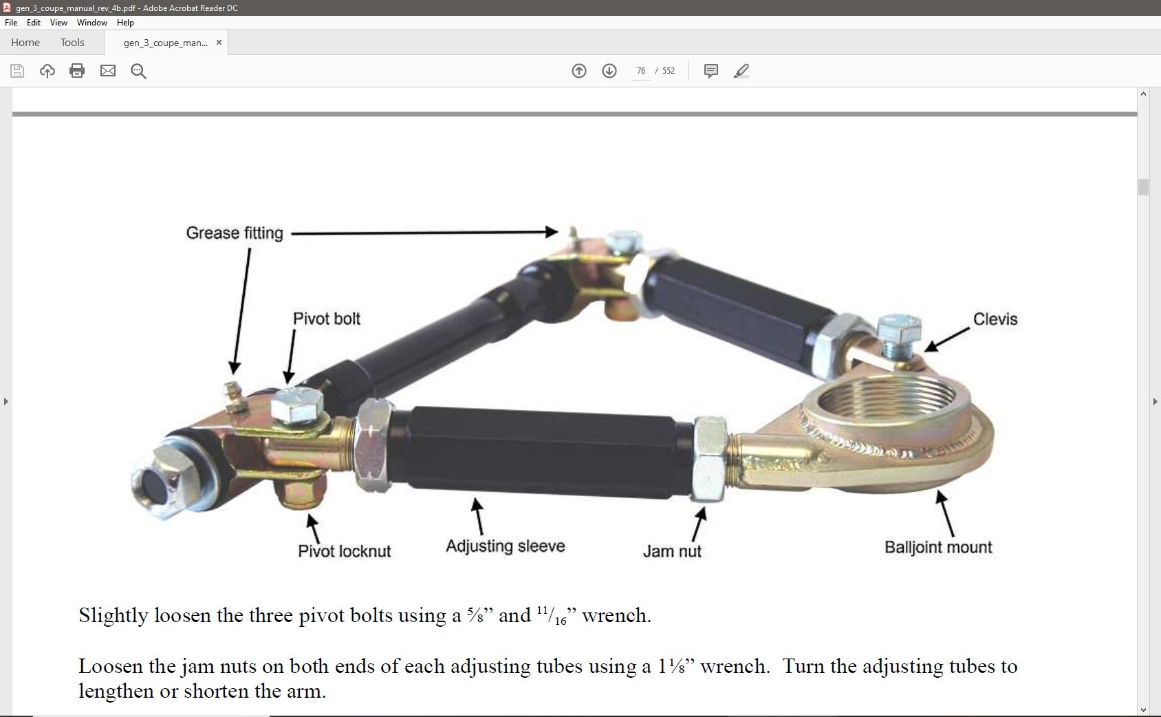
Sorry to be the bearer of bad news. But you've fallen victim to the upside down UCA assembly error. It's really too bad how often it happens. You're not the first or probably the last unfortunately. The UCA's are from a vendor to Factory Five and are a standard part. Out of the box they are partially upside down for our builds. The pictures and explanations in the build manual show them properly oriented. But don't specifically say they have to be disassembled and reassembled to get them that way. Note this page from the Coupe build manual. Shows the angle of the ball joint, which you have correct. But the pivot on the arms should be on the top half of the shaft, and the zerk fittings should point up as pictured. Easy enough to fix by removing the two rear pivot bolts, flipping it over, and put them back together before assembly. Hopefully you only have the one side done as mentioned. So that one you'll have to unbolt from the frame in addition to flipping over. Minor setback. 
Last edited by edwardb; 02-25-2019 at 01:26 PM.
Build 1: Mk3 Roadster #5125. Sold 11/08/2014.
Build 2: Mk4 Roadster #7750. Sold 04/10/2017.
Build Thread
Build 3: Mk4 Roadster 20th Anniversary #8674. Sold 09/07/2020.
Build Thread and
Video.
Build 4: Gen 3 Type 65 Coupe #59. Gen 3 Coyote. Legal 03/04/2020.
Build Thread and
Video
Build 5: 35 Hot Rod Truck #138. LS3 and 4L65E auto. Rcvd 01/05/2021. Legal 04/20/2023.
Build Thread. Sold 11/9/2023.
-
You are an observant man edwardb! I noticed last night that the zerks were in an awkward position but I had not had a chance to go back and figure out what was wrong. Thanks for the guidance, it was as you said an easy fix and they are correct now.
-
Senior Member
Originally Posted by
Gadsden
You are an observant man edwardb! I noticed last night that the zerks were in an awkward position but I had not had a chance to go back and figure out what was wrong. Thanks for the guidance, it was as you said an easy fix and they are correct now.
I wouldn't say observant so much as it happens so frequently it's the first thing I look at when someone posts their new front suspension build. Glad it was an easy fix. More commonly builders put the ball joint in upside down and that's a harder fix. Onward!
Build 1: Mk3 Roadster #5125. Sold 11/08/2014.
Build 2: Mk4 Roadster #7750. Sold 04/10/2017.
Build Thread
Build 3: Mk4 Roadster 20th Anniversary #8674. Sold 09/07/2020.
Build Thread and
Video.
Build 4: Gen 3 Type 65 Coupe #59. Gen 3 Coyote. Legal 03/04/2020.
Build Thread and
Video
Build 5: 35 Hot Rod Truck #138. LS3 and 4L65E auto. Rcvd 01/05/2021. Legal 04/20/2023.
Build Thread. Sold 11/9/2023.
-
I found the straight lower "A" arm zerks were not easy to get at so I changed them to angled ones.
David W
Mkll 4874 built in 2004
Gen 3 coupe #16 registered 2018 painted 2019
-
Originally Posted by
Gadsden
The other big milestone for this week was making my payment to Blue Print engines, writing a check/wire for that kind of money is always painful, but very exciting as well. I am expecting delivery in late March. Based on the above feedback, I will wait and see what shift location works best for my engine/TKO 600 combination.
This is how my Dart 302-347/TKO 600 shifter positions looks. I followed the manual and turned the rear shifter 180 deg, not considerig the engine / transmission combination used there. Had I known, I would of course ordered the transmission with the mid shifter allready installed. Then again, now I will have a look at the Tremec internals.
I have test fitted the unit at an early stage so I better can position wires, fuel lines, PS hoses and so on.
Tremec.jpg
Last edited by Sigurd; 03-30-2019 at 02:26 AM.
Reason: Added pic
-
Thank you Sigurd.
I have actually followed up with Factory Five and your input confirms what I was told. I either need to use the mid shift location or could use the rear position but it would require modifying the frame. Roughly mocking up positions, I like the mid location and I really don't want to cut the frame! I will not do anything until I have test fitted and confirm for myself.
-
I have had some delays for the last couple of weekends between trips back East to visit family in the hospital and due to last minute wedding details/planning. After this coming weekend, I hope to spend more time on the Coop. The name "Coop" by the way is a play on words, as my oldest name is Cooper.
There has been some milestones achieved though. On 3/8 I received my last shipment from Factory Five. I now have everything that was on the POL. I placed my order at the end of November. It was ready for pick up 12/22, but did not get picked up for a few weeks. Most items on my POL ended up coming in during that period.
Last night my engine / trans showed up from BluePrint: 20190318_182131.jpg
I can't wait to get a few mins to pop open that create.
I right now, I almost have the front suspension completed, just need to do get the rotors and calipers mounted. I hope to start spending more time and posting more updates/questions in the coming weeks.
Thanks for everyone's support so far!
-
Post Thanks / Like - 0 Thanks, 1 Likes
-
Still working on the front end. I decided while I was in the front, to do the swaybar. I was not able to find any Coupe specific install instructions so basically used the Roadster instruction as a guide. Considering this is a new build and I have not done anything to adjust ride height or spring compression, should I follow the instructions and start in the 2nd hole for the swaybar? I can easily use the 3rd hole, but not sure if that may present difficulties later on. What have other builders with similar 427 engines settled on for the swaybar? Do you find the 2nd hole a good setting or do you need to go to the 3rd?
Also, I finally opened the crated package from Blueprint and looked at my dyno sheet. My engine dyno'ed 553.3 HP and 532 ft/lbs.
For this weekend I hope to get the steering mocked up so that I can make sure everything is centered and then mount the rotors and calipers. Then I will move on to the rear IRS. I still need to paint/treat the diff, spindles and hubs with either clear coat or POR15.
Thanks for any info on the swaybar settings.
-
Now a real question
Hi support group!
I have what seems like a big question now around the steering rack. I have the FF5 supplied power steering rack and I am also using the Moog tie rod ends. The tie rod ends are not even close as far as thread engagement goes. looking from under the Moog tierod ends, the driver side has approx .5" of thread showing. The passenger side, shows no threads and the end is approx. .8 inches from showing. I know that the passenger side has over 1 inch of thread engagement, but this difference seems like a lot.
How did I get here? I thought I centered the rack. I installed the steering parts and found that from lock to lock was 2 and 1/4 turns of the steering shaft. I placed tape on the upper shaft and marked top at full lock. Then it rotated the shaft as best i could measure 1 and 1/8 turns to get to the middle. With this method the difference described above was the result.
I found this thread but it is roadster specific, and i *think* there may be differences between the coupe and roadster. https://thefactoryfiveforum.com/show...etup-Procedure
What do the experts think? Is this difference something to be concerned about? Was my centering process and logic faulty?
Any input would be great.
Thanks
-
Top Notch Builder

Originally Posted by
Gadsden
...should I follow the instructions and start in the 2nd hole for the swaybar? I can easily use the 3rd hole,... What have other builders with similar 427 engines settled on for the swaybar? Do you find the 2nd hole a good setting or do you need to go to the 3rd?
I went for the third hole. Instructions say if it seems like there is too much lean then go for the third hole. This implied the possibility of roll or lean and I wanted a car that corners like it’s on rails so I went for the 3rd hole. Plus 3 is more than 2 so it's gotta be better right? J/K. But seriously I did give this a lot of consideration I am sure there is a sacrifice in ride comfort for performance as there usually is. I imagine with 553HP you’re going to want things tightened up to control all that power you’re putting down whether it's in the corners or the straights. I am doing a Roush 427, sadly mine is not making 553HP.
Last edited by P100DHG; 04-04-2019 at 08:00 PM.
-
Originally Posted by
P100DHG
.... Plus 3 is more than 2 so it's gotta be better right? J/K. ....
I like the way you think. 3 is better than 2...Kind of along the same lines as "it goes to 11!"
Thanks for the input.
-
Wrapped up the front end last weekend. I think i got the steering rack centered. and have similar thread engagement for each tie rod end.
Moved on to prepping the IRS components. Got the ear cut off of the spindles. Each spindle took a single general purpose demolition sawsall blade from Harbor Freight. Other than that, no surprises. I followed some others lead on this board and left a little more material than the manual called for:
spind.jpg
For the 2 holes in the spindle, I had seen a couple of approaches to address those. I did not want to leave them open and I thought the set screw approach was nice and clean. I got 2 of my boys to help tap the holes, 1/4 - 20 for the smaller and 7/16 - 20 for the larger hole. I got some 3/4 inch set screws from McMaster and it worked out great. tapping2.jpg
Knocking out the stock studs was a lot easier than I expected and they came out with out too much hammering. To install the FF5 supplied studs, I ground a slight flat for clearance on the back of the hub and then sucked them on with washers and a nut. It is a little hard to see in this pic, but you can see the flat:
hub.jpg I had difficulty finding a 1/2 - 20 hardened nut, I tried a Grade 5 nut and it only worked for 2-3 studs before being completely worn out. I found some Grade 8 nuts at Ace and they worked much better.
Lastly I enlarged the mounting holes on the front of the diff. This was by far the toughest task of the weekend. Even starting with a step bit, the bit kept binding and wanting to twist the drill out of my hands. I used a battery powered drill instead of my 1/2 corded drill to try an minimize the pain. With some patience and lots of WD-40, I got them drilled out.
I am still waffling between using POR15 on the spindles and hubs or not. I will use it for the diff. Next up is to make some alignment pins like edwardb made to help with the diff install, and maybe move on to that this weekend.
-
Senior Member
I sprayed Duplicolor Clear Engine Enamel on the spindles and diff cover to keep them shiny and metallic. I can't remember off hand about the hubs but POR will work if you avoid the bearings.
Gen 3 Type 65 Coupe builder
-
Originally Posted by
q4stix
I sprayed Duplicolor Clear Engine Enamel on the spindles and diff cover to keep them shiny and metallic. I can't remember off hand about the hubs but POR will work if you avoid the bearings.
That is exactly my plan for now, definitely will keep the diff cover as it came, and clear coat it. The rest of the diff, I will POR15.
I clear coated the back of the front hubs, and will do the same for the rear. I think i am set to clear coat the spindles too, I like the look of the aluminum.
Thanks for the input!
-
Finally back at it this past weekend. Spring in Colorado is here and it was much nicer than those winter days with garage temps in the 30's. The last 6 weekends were taken up with flag football season and between coaching 2 teams my weekends were shot, but fun!
We finally got to spend some quality time in the garage this Saturday and got the diff installed. It took us about 4.5 hours to complete the job. That included discussions on safety when lifting heavy objects, explanations on what a diff is and how it works, and lessons on leverage! In the end, we got it done and had a pretty good time in the process.
I followed some others advise and made a few alignment pins out of 5/8 bolts. These came in very handy. I also used a combination of my engine hoist and a floor jack to lift the diff. By applying pressure from either below or above I was able to better control pitch and alignment. Once I got it into position i had trouble with the bushing pushing out when the front mounting bolts were pushed through. After a few failed attempts and comically getting a box wrench stuck, I was able to get the bolt through and then squeeze the bushing back in with some channel locks.
Here are a few pics to show my process:
Getting the hoist ready, pretty good team work for brothers that are better at fighting than cooperating: hoist.jpg
The diff slung up and just off the dolly: lift1.jpg
The diff on it's way up: lifting.jpg
The jack and hoist in use: liftsupport.jpg
The jack man concentrating: jackman.jpg
Wiggling it into position: shifting.jpg
The diff in position and all the bolts started: inplace.jpg
Last day of school is tomorrow and then we are off on vacation for a week. Once we return, we are on to the rear suspension, hubs, spindles, half shafts, etc.
-
Back At It
We were back at our "Colorado Coop" build this past weekend. Made some good progress and a small mistake that needs addressed. Focused on the driver side only. Will tackle the passenger side next weekend and learn from my mistakes.
Per the manual i assembled the Toe Arm and Upper Control arm. Then installed Toe, Lower and upper control arms. Nothing too remarkable to report here. They went in with out much issue. They all went in with slight persuasion with a rubber mallet. Here are all the arms installed:
arms installed.jpg
Next up we got the spindles and hubs ready to install. I am going to run some 25mm Eibach wheel spacers, so the F5 supplied studs needed to be trimmed, they are just a little too long and the wheel clashes on them. I measured 2, 3 4 times to make sure I knew exactly how much to take off. Then I waited a couple of weeks to make sure I did not forget anything. We cut them off with a cut off wheel without any issues. Here we are removing the nut that was run on prior to cutting:
backoff_nuts.jpg
With the spindles ready to go, it was time to install the prop-shaft. This went in pretty easy. Again it took slight persuasion with a rubber mallet to drive it in. These 2 pics show us getting ready to and installing it:
propshaft.jpg
Going_in.jpg
Finally it was time to connect all the arms to the spindle. This took longer than expected and I needed to make a spreader from a spare bolt, nuts and spacers to spread the Lower and Toe arm mounts. The mounts were very close, but just tight enough that the spindle mount points would not go in. Here is the spindle getting ready to mount the arms:
attach_spindle.jpg
Once this was all done I was feeling pretty good. I reviewed the manual to make sure I did not forget anything and to see what was next. It was at this point that I realized my mistake from earlier in the day. The next step for me is to install the rear breaks. I started to think through the steps and I realized that my measurements and measuring procedure for how short to cut off the studs was flawed. When I measured I did not factor in the rotor. As a result, all 10 studs are cut too short! I now have replacement studs on order from Summit and will press out the short studs with a hammer later this week and then re-measure with the rotor and spacers in place before cutting the new ones. I will need to pull off the driver side spindle but the passenger side has not been installed yet. So that will be a couple of hour set back to take my time and make sure I get it correct this time.
One other thing I noticed was that in the manual for installing the diff, it stated to torque the mounting bolts to 100 Ft/lb. Then at the end of the section of the manual the torque value table says 129 ft/lb. I think 30 ft/lb is significant enough to go back an re-torque those bolts.
Looking forward to next weekend and getting the passenger side done and fixing my measuring mistake.
-
Summit Package Arrived
Got a nice visit from the UPS truck this afternoon. Summit amazes me with how fast they ship. This order was placed late Sunday night and I had it by lunch time Wed. The main item was the replacement wheel studs, but in order to save $9 in shipping, I had to spend another $75 to get free shipping :-) So I also ordered a few other items that I will be needing.
This order was:
- Dorman Wheel Studs 610-290
- Craftsman Thread Pitch Gauges 009-52317 (don't know how i got by without this before)
- Dupli-Color Engine Enamel with Ceramic Resin DE1636 (going on my 3rd can of this stuff now)
- Summit Racing® Driveshaft Safety Loops SUM-G7900
- K Tool Engine Slings 62115
summit.jpg
Now I can start re-doing the studs and move past this small issue.
-
I need some input
While torquing the new wheel studs to 100ft/lb per the manual, one of the studs stared spinning in the hub. I am having a hard time figuring out if the metal on the hub gave way or if the serrations on the stud failed. I do see some flat smooth areas on the stud, but I am not sure what the inside of the hole on the hub should look like. I am hoping that it was the stud and i just need a new stud.
Has anyone else seen the serrations on the studs give?
Thanks for any ideas, input or advise on next steps. I hope a new stud is the answer, possibly a better quality like ARP.
*Update* I put a caliper on the knurled section of the blot and it is quite a bit less than the .619 inch spec. I am hoping that this is a good indicator that replacing the bolt is all that is needed.
Brian
Last edited by Gadsden; 06-15-2019 at 08:57 PM.
-
It has been several weeks since posting here, but we have been making good progress. I recovered from the wheel stud issues. I ended up pressing the new studs into the hubs.
The rear suspension is now completed and the Wilwoods mounted. Nothing really unexpected during this process. I did have some clashing issues with the parking brake caliper but that was because the control / toe arms were WAY out of spec. Tightening up those adjustments took care of the parking brake caliper hitting the spring. I leveraged a lot of ideas and suggestions from this place. I did make a crude spreader for the toe arm and lower control arm connections to the spindle.
Here are me and my son finishing up the suspension
B-C PS suspension.jpg
Coop suspension.jpg
Here are a few other pics of the suspension :
halfshaft.jpg
suspension complete.jpg
UCA.jpg
UCA2.jpg
UCA-Toe arm.jpg
The brakes are mounted and parking brakes roughly adjusted:
suspension brakes 2.jpg
suspension brakes.jpg
This weekend we moved on to the fuel tank. I will provide some info on that work shortly.
-
Post Thanks / Like - 0 Thanks, 1 Likes
-
E-Brake Issue found and resolved
I ran into an issue with the Wilwood E-brake adapter that was received with my kit. Unfortunately, I did not realized that I had the wrong part until after it was powder coated. The issue was that the adapter had no way to insert the end of the e-brake cable.
Below is a picture of what i received in my kit:
20190817_143127.jpg I would be interested to know if anyone knows what kit these "incorrect" parts are really for.
I emailed Factory Five on Sunday afternoon and had a reply first thing Monday morning. I received the replacement parts Wednesday afternoon. What I received was significantly different than what came in my kit. The adapters for one thing are quite a bit smaller, but it also included 2 spacer/extensions to address the issue connecting the cable to the handbrake assembly. In several builds i read where people needed to fab their own. It looks like it is part of the kit now.
Below is a picture of the new parts:
20190821_183932.jpg
Planning to get these parts installed this weekend and move on to the fuel tank installation.
-
FFR Maven

I have the same "incorrect" parts as you.... the L-shaped bracket with a square hole in the smaller leg. I expected them to be for the Wilwood parking brake cable-to-caliper joint, but they're not correct for that. Doesn't matter to me since I'm not using the FFR Wilwoods, but I'd still like to know if these "incorrect" brackets have some other intended use.
-
Originally Posted by
Gadsden
I ran into an issue with the Wilwood E-brake adapter that was received with my kit. Unfortunately, I did not realized that I had the wrong part until after it was powder coated. The issue was that the adapter had no way to insert the end of the e-brake cable.
Below is a picture of what i received in my kit:
20190817_143127.jpg I would be interested to know if anyone knows what kit these "incorrect" parts are really for.
.
I believe that part is #15170 Emergency Brake Mounting Bracket that came with my Gen2 coupe.
If you look close you can see I had that in my list to get powder coated, see right in below picture:

Can see it used here:

Thanks.
-Matt
-
Senior Member
Originally Posted by
mtwarog
I believe that part is #15170 Emergency Brake Mounting Bracket that came with my Gen2 coupe.
If you look close you can see I had that in my list to get powder coated, see right in below picture:
Can see it used here:
Thanks.
-Matt
If those are the pieces in question (looks like they are) not used on the Gen 3 Coupe. Part of the standard E-brake kit of parts. But the Gen 3 Coupe mounts the E-brake handle on top of the tunnel and has mounting brackets already installed in the frame. Those pieces aren't used.
Build 1: Mk3 Roadster #5125. Sold 11/08/2014.
Build 2: Mk4 Roadster #7750. Sold 04/10/2017.
Build Thread
Build 3: Mk4 Roadster 20th Anniversary #8674. Sold 09/07/2020.
Build Thread and
Video.
Build 4: Gen 3 Type 65 Coupe #59. Gen 3 Coyote. Legal 03/04/2020.
Build Thread and
Video
Build 5: 35 Hot Rod Truck #138. LS3 and 4L65E auto. Rcvd 01/05/2021. Legal 04/20/2023.
Build Thread. Sold 11/9/2023.
-
Thanks mtwarog, you are exactly right, that is what the parts in question were for. As Edwardb said, the Gen 3 mount is different and it bolts directly to the chassis.
The replacement kit that F5 sent worked perfectly and also included some extensions to extend from the cable ends to the handle assembly. I know Edwardb and others had to come up with their own solution to get the extra couple of inches. F5 now includes that.
I will update with pics of the completed install soon.
-
E-brake and fuel tank in
Last weekend got the e-brake installation completed. As i mentioned earlier, there were some missing parts that F5 sent out extremely quickly. Once I had the right parts it went pretty smoothly with no more surprises.
Below is a picture of the handbrake assembly. You can see the new extensions that F5 provided. I did end up putting a spare nut between the cable end of the extensions to take up some space. You can see in this pic how the assembly attaches to the frame as opposed to the Gen 2 pic a few post up.
handbrakeassy.jpg
Next is the correct Wilwood adapter that I was initially missing. I did have to open up the slot slightly to get the cable end in, but nothing big. I also adjusted the calipers, one was way out of adjustment, the other was pretty close, but it all works nicely now.
ebrakeadapter.jpg
Lastly the fuel tank is installed and this coming weekend i will continue to follow the manual for the next steps. I think it is time to be ordering some line bending tools :-). I silicone'd thin strips of rubber around the perimeter of the tank where is meets the frame. I just did not like the idea of metal on metal here. The only issue with the install as i did need to get longer bolts to get the straps bolted up. I ended up needing to get 3 inch bolts, which were about half an inch longer, if I remember correctly. Not too interesting of a picture but here is the tank in place:
tank.jpg
Long holiday weekend coming up and I am hoping to spend a fair amount of time with this project, but my family may disagree!
Last edited by Gadsden; 08-29-2019 at 01:40 PM.


 Thanks:
  Likes:


 Reply With Quote


