-
Senior Member

#8793 MK4 Build ('15 IRS, '16 Coyote, 15" wheels)
The Goal: Build a proper drivers car that has great feedback, balance, brakes, and comfort. Keep it very classy with paying tribute to the originals. Make it well thought out so everything works very well together. Make it an enjoyable care that can be comfortable as a DD if need be and enable my wife or myself to be able to jump in it and go anywhere without worry. Also set it up so I can run it at track days with a simple wheel/tire swap.
High level build spec:
- 2015 IRS
- 2015/15 Coyote 5.0 (From Forte)
- T-56 Mag (from Forte)
- 15" Wheels for street, 17" for track with slicks
- Big brake kit for 15" wheels (Levy)
- Soft Top
- No stripe, no hood scoop, under car exhaust, and a bunch of other 'stuff'
- 3/1/16 - Edit, added P/S from Forte & Kirkey Vintage Buckets as I don't fit into the stock seats
FFR order list:
- Full Kit, plus the following:
- 12189 – Powder coated chassis
- 15442 – J-pipes:5.0L Coyote
- 15440 – 4/6L/5.0L Coyote Mounts
- 14761 - Driveshaft 31 spline, any length
- 14260 – Upgrade: Leather Roadster Seats
- 12066 – Tubular Front Lower Control Arms
- 14769 – Independent Rear Suspension Kit, standard axle width w/Koni shocks
- 16004 - Factory Five Racing Vintage GPS Gauge Set
- 15330 – Upgrade: Polished Stainless Bumpers.
- 16039 - Upgrade: Padded Vinyl Dash with Glovebox
- 14816 - Heater-Defroster
- 12453 - Battery Cutoff Switch
- 15998 - 2015 IRS Real Sway bar
- 12049 – Wind Wings
- 12042 – Sun Visors
- 15549 – Vintage Wiper Kit
- 15101 – Upgrade Chrome Driver Side Roll-Bar
- 15158 - Roll Bar Grommets with Trim Rings & Hardware
- 15432 – Roadster Coyote Installation Kit
- 15659 - Side Louver set
- 16095 - IRS Takeout - '15 mustang w/3.55
- 15199 - FFR Soft Top
- 14932 - Stainless Steel Exhaust (not being used, free upgrade)
- 16116 - Front sway bar
- FFR 15" wheels
- FFR 17" wheels (track wheels for slicks)
Item's ordered with motor from Mike:
- 2015 Ford Mustang 5.0 Coyote Motor
- Engine cover kit
- Alternator kit
- Engine ECU
- Clutch kit
- Starter
- Clutch fork
- Clutch bolts
- Bellhousing
- Transmission (Tremec Magnum 6 speed)
- Aftermarket Motor oil pan
- Fuel pressure Regulator
- Fuel pump
- Speedo recalibration tool
- Air intake & filter
- Radiator fill tank
- Hydro clutch kit
On with the build.
Last edited by Duke; 03-01-2016 at 03:24 PM.
-
Senior Member
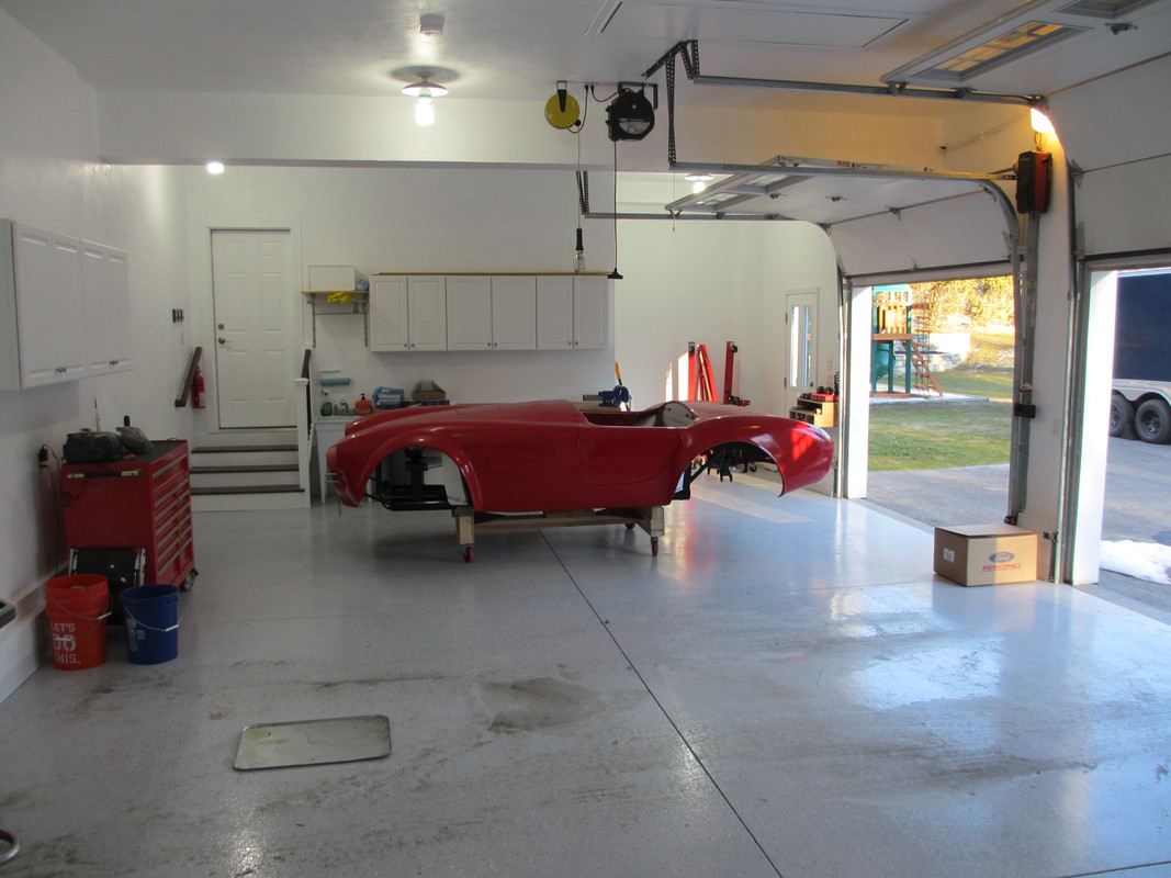
Pickup from FFR first of year on a cold 10 deg. day and a little snow. Once in the trailer we strapped it down and promptly broke the back wheels off the dolly with the ratchet straps, lol. It took about 2hrs or so to jack the whole thing up in the trailer, cut out the dolly in half, fix it, and put the dolly back under the frame before rolling it out. At least it was a little warmer that day.
IMG_0068.jpg
-
Senior Member
-
Senior Member
-
Senior Member

Exciting looking build. Now that's a grocery list of stuff! Will be interested to see the 15 inch wheels and brakes with the 2015 IRS. Lots of talk about it but haven't seen one come together yet. Two quick observations: I see you have "Speedo recalibration tool" on the list from Forte. The official word from Ford Racing is that module is not required for the 2015-2016 Coyote. I've talked to them myself, and they assured me the new PCM no longer needs it. Also, don't see power steering on your list. With everything you've listed, including your goals for the car, surprised not to see it. Personally, I would recommend you consider it.
Build 1: Mk3 Roadster #5125. Sold 11/08/2014.
Build 2: Mk4 Roadster #7750. Sold 04/10/2017.
Build Thread
Build 3: Mk4 Roadster 20th Anniversary #8674. Sold 09/07/2020.
Build Thread and
Video.
Build 4: Gen 3 Type 65 Coupe #59. Gen 3 Coyote. Legal 03/04/2020.
Build Thread and
Video
Build 5: 35 Hot Rod Truck #138. LS3 and 4L65E auto. Rcvd 01/05/2021. Legal 04/20/2023.
Build Thread. Sold 11/9/2023.
-
Senior Member
One tool note that may help folks looking to adjust the koni coil overs for FFR's. After ordering the Jegs and trying another spanner wrench I had on hand I finally found this one that works perfectly. The Koni's have round holes (pins) rather than the square holds for the adjustment wrenches. This tool fits perfectly and gives you enough had room to work around the LCA.
Stanley Proto JC494 Proto Adjustable Pin Spanner Wrench
http://www.amazon.com/gp/product/B00...ilpage_o00_s00
-
Senior Member

Originally Posted by
edwardb

Exciting looking build. Now that's a grocery list of stuff! Will be interested to see the 15 inch wheels and brakes with the 2015 IRS. Lots of talk about it but haven't seen one come together yet. Two quick observations: I see you have "Speedo recalibration tool" on the list from Forte. The official word from Ford Racing is that module is not required for the 2015-2016 Coyote. I've talked to them myself, and they assured me the new PCM no longer needs it. Also, don't see power steering on your list. With everything you've listed, including your goals for the car, surprised not to see it. Personally, I would recommend you consider it.
Thanks, yes it should be interesting to see how the 15's fit. Thanks for the heads up on the Speedo tool. I'm not going PS on this build or power brakes. I'm really focused on getting the road feedback/input. I race Karts (and just about anything else I can get seat time in) so I'm all about getting the right driver feedback/experience. I can always throw it on later if it really is necessary.
Other challenges I know I'm going to run into. I would love to do the glove box and heater. Heater is priority, glove box is optional, but desired. I may end up getting creative and fabbing up my own heater box, or move it into the trunk. We'll see. Other items are seats. I'm 6'4" and my wife is 4'10". I'm going to have to make something work for both of us. Sliders are a must, but the stock leather seats I bought have me sit too high. I'll probably end up getting Kirkey Vintage Roadster seat, get them custom foamed and covered locally and integrate heaters into them. I want the look of the stock seats, but I need to sit down lower. Other 'stuff' includes LED head lights, front brake ducts, and some other items. I have a build sheet I made and manage before I started the project. I do this with all the cars I build to help manage what I'm doing and overall budget.
-
Senior Member
Originally Posted by
Duke
I'm not going PS on this build or power brakes. I'm really focused on getting the road feedback/input. I race Karts (and just about anything else I can get seat time in) so I'm all about getting the right driver feedback/experience. I can always throw it on later if it really is necessary.
Agree about the brakes. No power for the Wilwoods. Sounds like that's what you're using from Gordon. But for the PS, you've obviously given this build a lot of thought, and I applaud you for that. I hesitate to say more, but you have such a nice build going, feel that a response is warranted. I won't turn your build thread into a debate about PS (heaven knows that's been done to death) but these statements for your consideration: PS and proper steering feedback are not mutually exclusive. With the right setup you can dial it in just the way you want it. Couple ways that can be done. It's not just about steering effort. It's also about front end alignment and the increased castor that can be dialed in with PS. Improves centering and straight ahead stability. Yes it can be added later. But it's easier now, cheaper (only buy stuff once), and that Coyote engine compartment is tight. (I know...) Best to fit it in during the build IMO. You will find that most guys that track their cars are also running PS. Finally, having had one with manual and one with PS, the difference in overall driving experience and enjoyment with PS is much more than I would have expected. That's it. Enjoy the build. And keep us posted with your progress. Build threads are some of the best stuff on here IMO.
Last edited by edwardb; 01-24-2016 at 09:05 AM.
Build 1: Mk3 Roadster #5125. Sold 11/08/2014.
Build 2: Mk4 Roadster #7750. Sold 04/10/2017.
Build Thread
Build 3: Mk4 Roadster 20th Anniversary #8674. Sold 09/07/2020.
Build Thread and
Video.
Build 4: Gen 3 Type 65 Coupe #59. Gen 3 Coyote. Legal 03/04/2020.
Build Thread and
Video
Build 5: 35 Hot Rod Truck #138. LS3 and 4L65E auto. Rcvd 01/05/2021. Legal 04/20/2023.
Build Thread. Sold 11/9/2023.
-
Senior Member
-
Senior Member
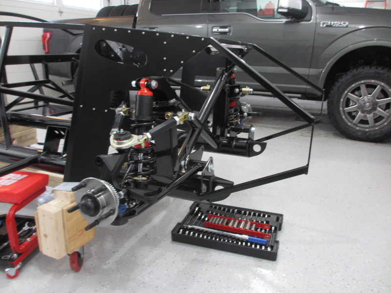
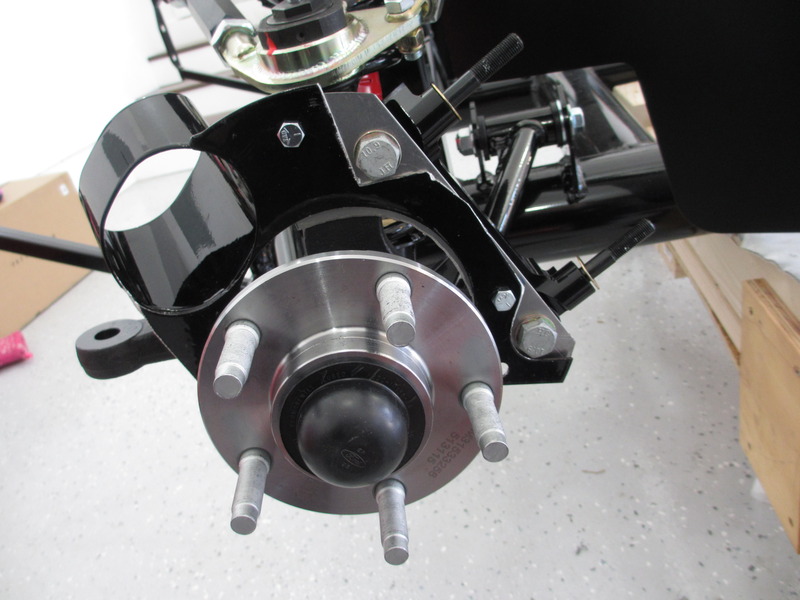
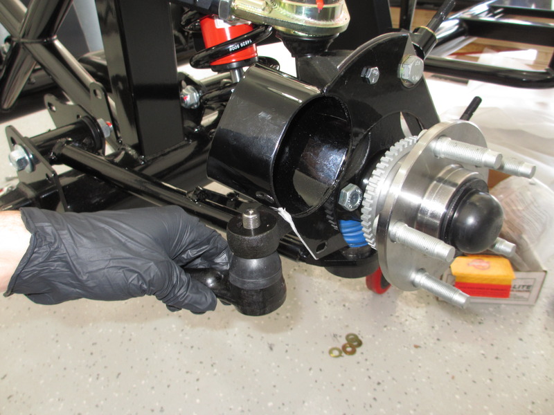
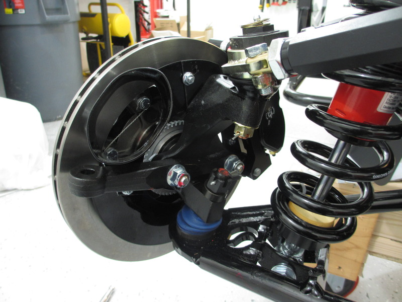
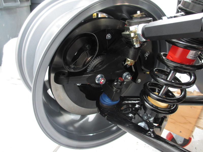
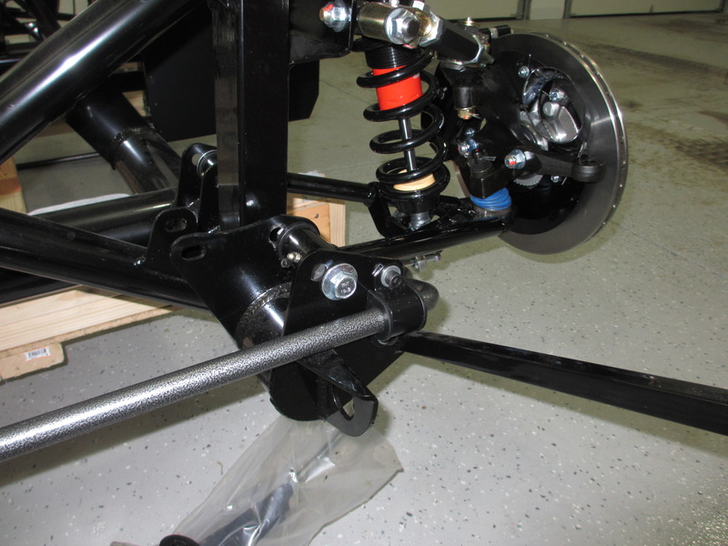
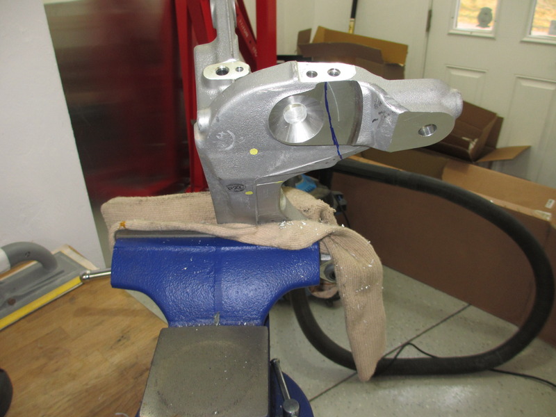
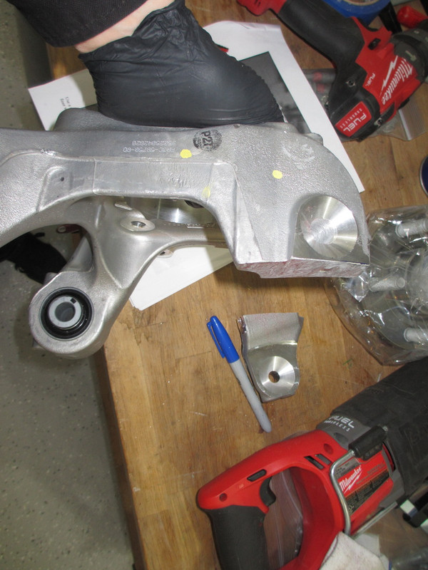
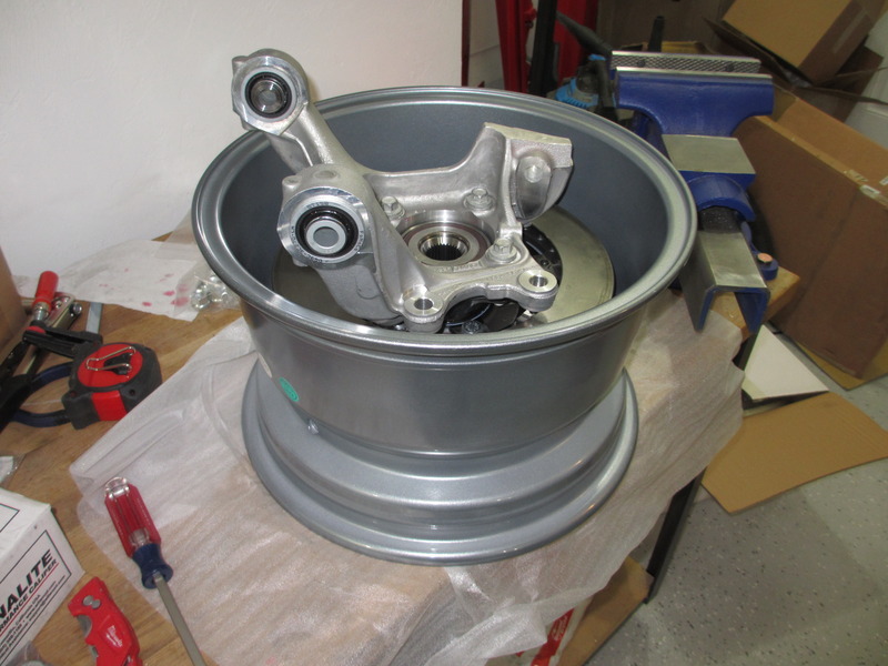
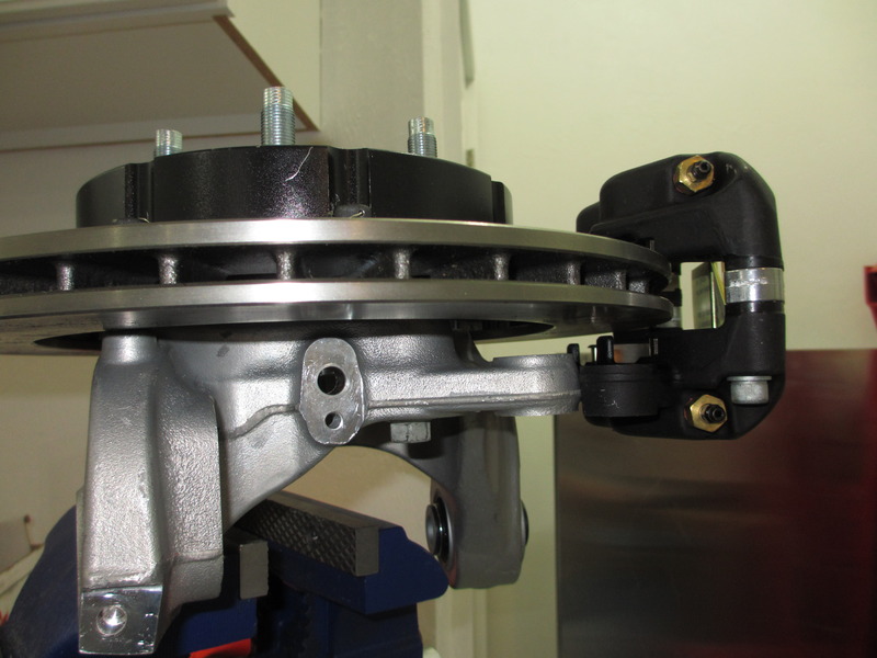
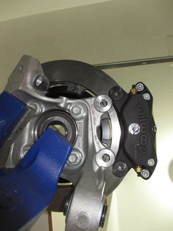
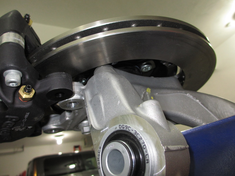
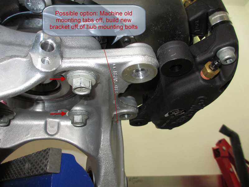
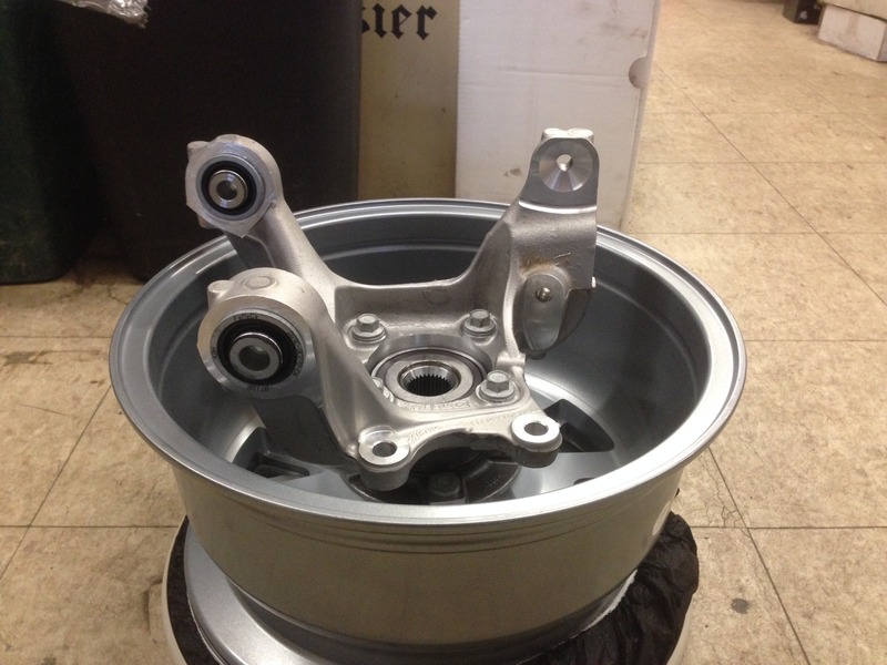
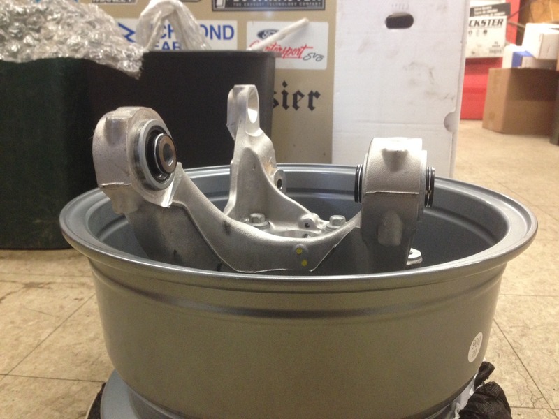
Great news, while I was picking up my new Coyote motor and 6-speed from Mike's shop today he happened to have a set of 2015 IRS spindles handy. I brought one of my 15" wheels and it looks like we are in business. Clearance doesn't appear to be an issue. These pics are without the Willwood discs because the spindles still had the larger studs in them. The disc hat will add another 1/4 or so of clearance. Now I'm just waiting my backordered spindles from FFR.
Last edited by Duke; 05-25-2018 at 08:26 AM.
-
Senior Member
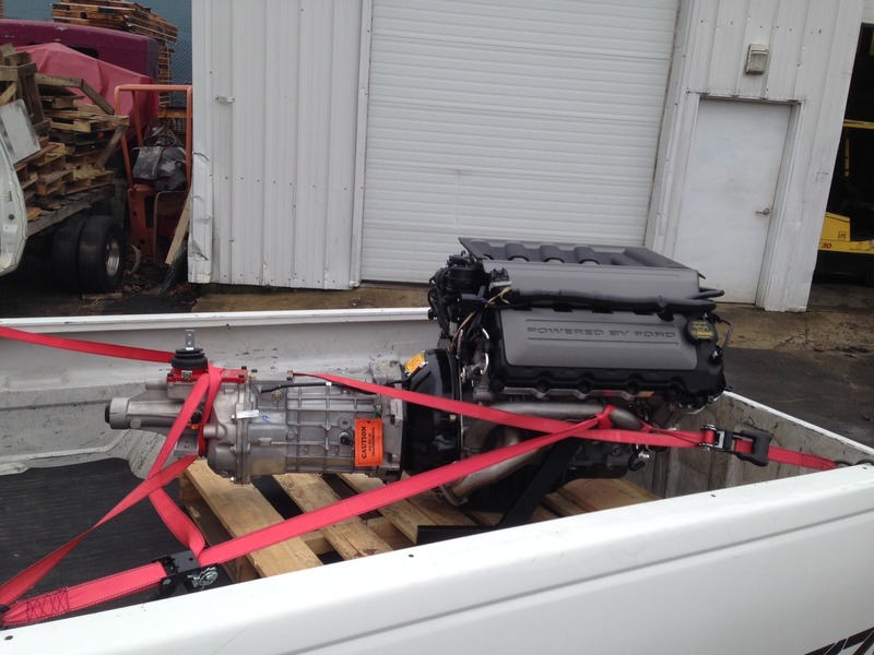
New bullet and 6-speed with all the extras courtesy of Forte's Parts Connection. Thanks Mike!
Last edited by Duke; 05-25-2018 at 08:26 AM.
-
Senior Member

Cool build! which rear wilwoods are you using? 12.88" rotor?
***SOLD!!! - NASA ST2 FFR#48 Gen3 Type65 Coupe R, Street legal.***
***SOLD!!! - NASA ST2 FFR#48 Challenge Car rolling chassis, Street legal.***
http://johngeorgeracing.com
-
Senior Member
Originally Posted by
johngeorge
Cool build! which rear wilwoods are you using? 12.88" rotor?
Levy's kit for 15" wheels (Wilwood 4 piston front and rear). 12.19"
For Rears: Hat: 170-3265, Rotors: 160-5844, Calipers: 120-6806
-
Post Thanks / Like - 0 Thanks, 1 Likes
-
 Administrator

I have Gordon's Wilwood kit under my 15" Trigos. I love them! I'm currently going over my build to get it ready to sell because I want to build a MKIV, almost exactly as you have your configured! Glad to see you can run 15" wheels with the new IRS! I wonder if there is any impact to going pin drive as well? It looks like it would actually have MORE clearance...
Great start to the build!

FFR 5369 Pin Drive, IRS, Trigos, Torsen, Wilwoods, FMS BOSS 302 "B" cam , Mass-flo. CA SB100 (SPCN) Registered
Delivered 4/23/06. "Finished" 4/2012 (still not done!)
-
Senior Member
-
Senior Member
-
Senior Member
-
Senior Member
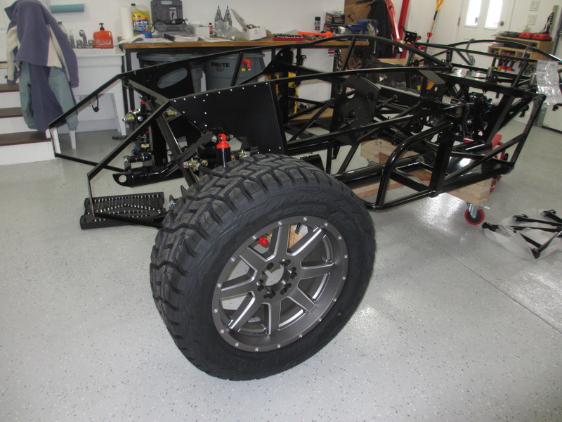
Forgot to mention. My new hill climb wheels and tires for the roadster came in too. Should be a good look for it right?
Last edited by Duke; 05-25-2018 at 08:27 AM.
-
Curmudgeon

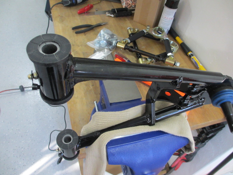
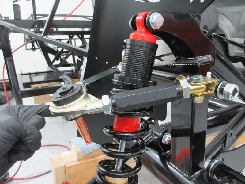
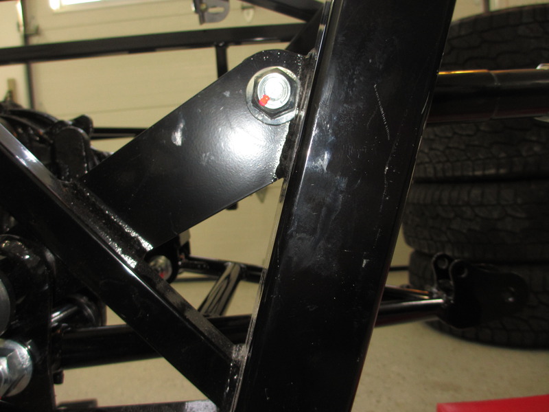
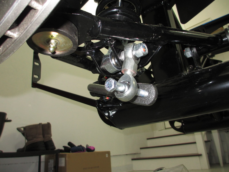
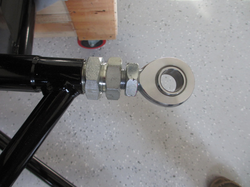
I'm curious about the heims on the IRS upper spindle mount. Any way to post more pics of it?
MKII "Little Boy". 432CI all aluminum Windsor. .699 solid roller, DA Koni shocks, aluminum IRS, Straight cut dog ring T-5, 13" four piston Brembos, Bogart wheels. BOOM!
-
Senior Member
Originally Posted by
mikeinatlanta
I'm curious about the heims on the IRS upper spindle mount. Any way to post more pics of it?
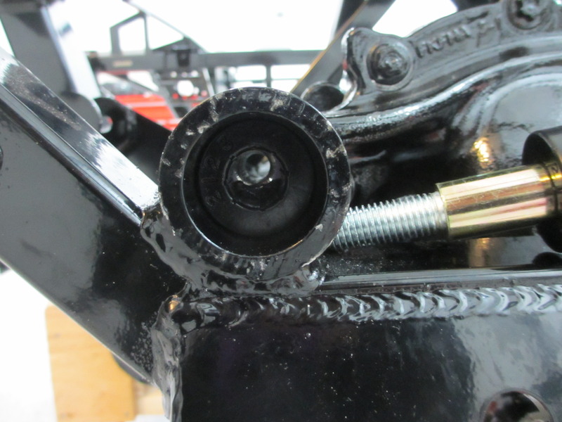
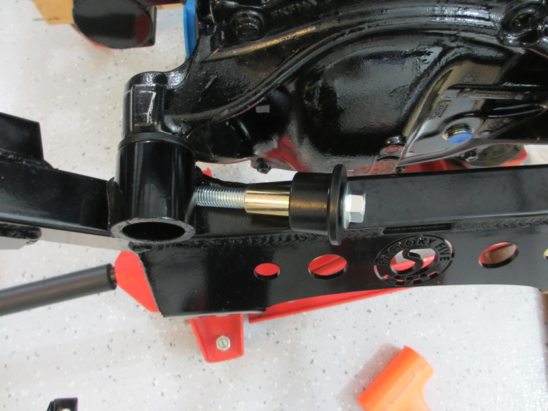
I assume you are looking for rear. Here's a quick shot after I backed out the threads so you can see a little better. The joint has a jam nut, followed by a threaded adapter, followed by a second jam nut.
Last edited by Duke; 05-25-2018 at 08:27 AM.
-
Senior Member
-
Senior Member
-
Senior Member
You're doing some interesting things there. Two hints. I know you're just mocking things up and looking for the best solutions. I do the same thing. A lot. But don't establish final seat location without the body in place. The final location and angle will be influenced by the body opening. Same thing for the footbox sheet metal. Ideally, your Coyote and whatever header setup you're going to use can be set in place so you can check things out. I too used the 2bking modded panels for my build, and they work out well. I'm surprised to see you're replacing the very newest FF design. I was under the impression it provided similar space.
Build 1: Mk3 Roadster #5125. Sold 11/08/2014.
Build 2: Mk4 Roadster #7750. Sold 04/10/2017.
Build Thread
Build 3: Mk4 Roadster 20th Anniversary #8674. Sold 09/07/2020.
Build Thread and
Video.
Build 4: Gen 3 Type 65 Coupe #59. Gen 3 Coyote. Legal 03/04/2020.
Build Thread and
Video
Build 5: 35 Hot Rod Truck #138. LS3 and 4L65E auto. Rcvd 01/05/2021. Legal 04/20/2023.
Build Thread. Sold 11/9/2023.
-
Senior Member
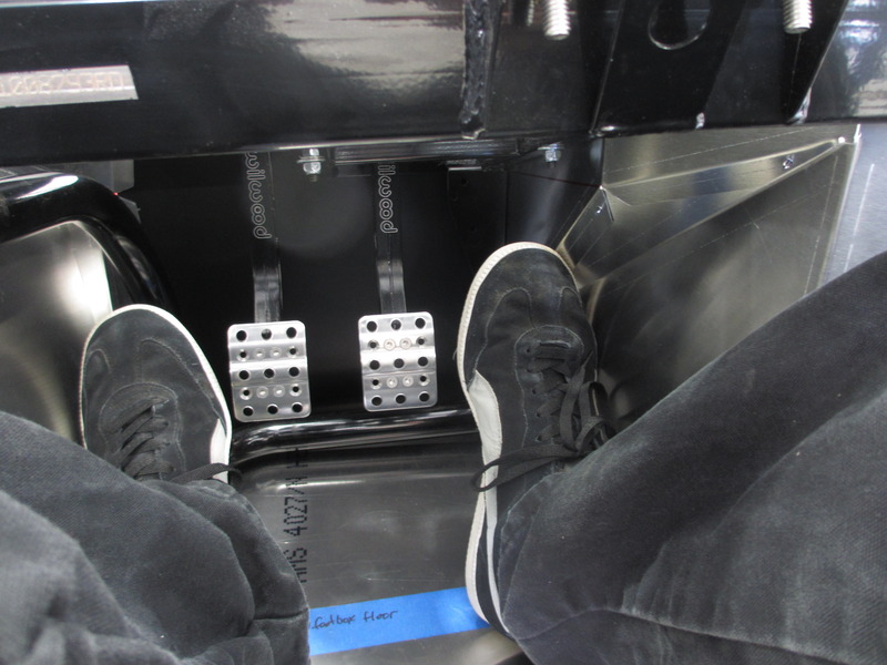
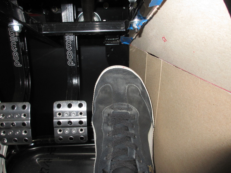
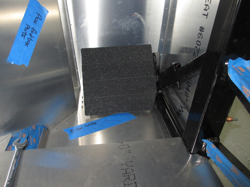
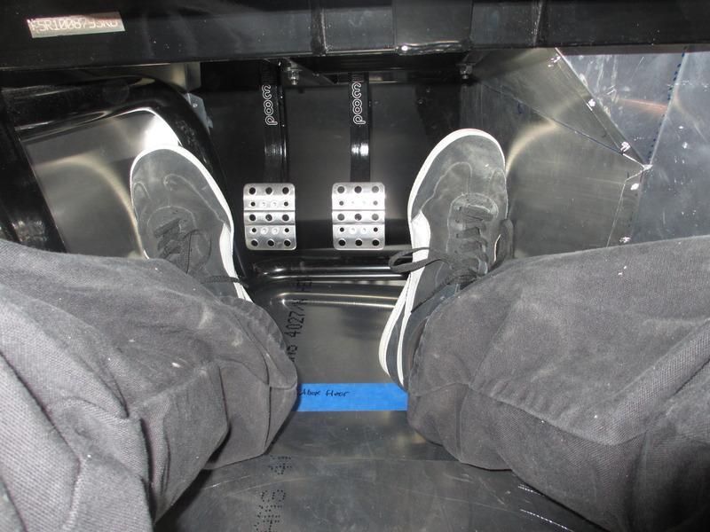
Thanks. Yes, everything including panels and seat will be temp until the last possible point. The latest design on the foot box will work with something around size 9 or smaller shoes in my opinion. You can see that I'm running out of room at the top part of my shoe against the inner panel. With the change using 2bking's design it should give me more depress area for the pedal before I run out of room and in theory be okay with the stock FFR BBK coyote headers. The headers are on back order so it will probably be a few months before I can do a mock up with them and check panel fitment.
Also, I stole your e-brake pulley idea. I put the lines under the 4" cross tube and thought this is a little dumb and will ultimately lead to a failure due to line friction; then I remembered you had done something with pulleys. $20 in parts later it's solved. Thanks.
-
I love the passenger side footrest. Great idea.. Keep up the great build!
-
Senior Member

Great build with many of the options I would choose on my next one.
Being a woman and driving a roadster w/o PS, you may want to think about it if your wife will ever drive it.
I love it on the open road, but manuvering around town and parking is more of a struggle than I like.
Nice build and thanks for the detailed pics.
-
Senior Member
So, after a lot of suggestions and discussing it with my wife today I think I'm just going to upgrade to PS. Might as well right?
-
Senior Member
-
Senior Member
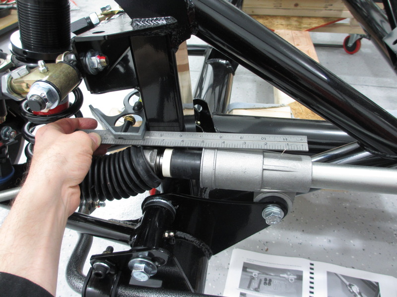
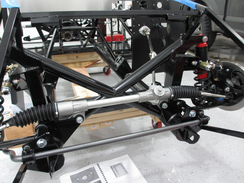
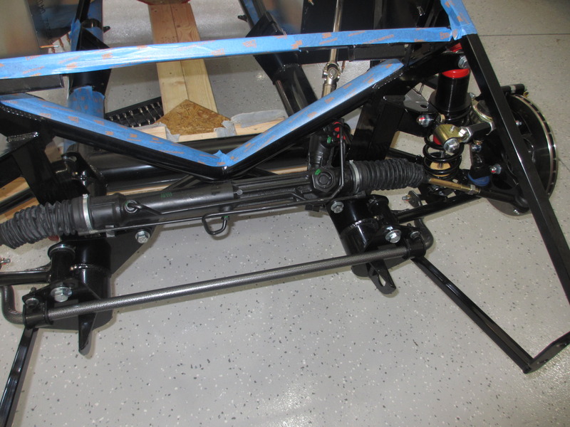
I was able to moved the pile forward last week. Mostly spent time doing fabrication work. I received some of my back ordered parts from FFR, including the fuel tank, the entire fuel tank packing list items, CV joints, windshield, and an extra reservoir I ordered for the clutch. I also picked up my power steering unit from Mike Forte. Very clean setup making it easy to access the lines. I'll post pictures and a write up once I into the motor.
First it was a quick install of the power steering rack. Very basic, just angle the driver side down first and having the passenger side as high as you can get it. Just watch your fingers on the passenger side as it can fall past the mount holes and nearly brake your finger. Mine is still black and blue.
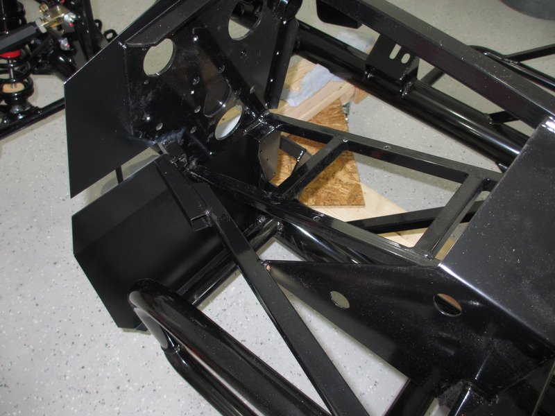
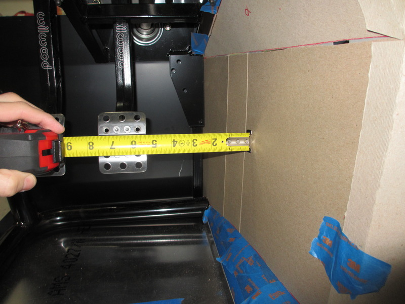
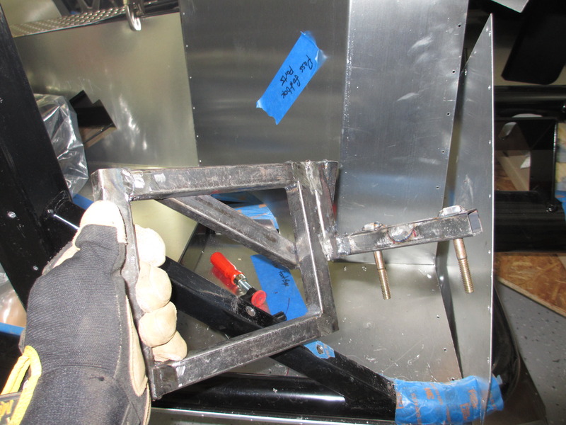
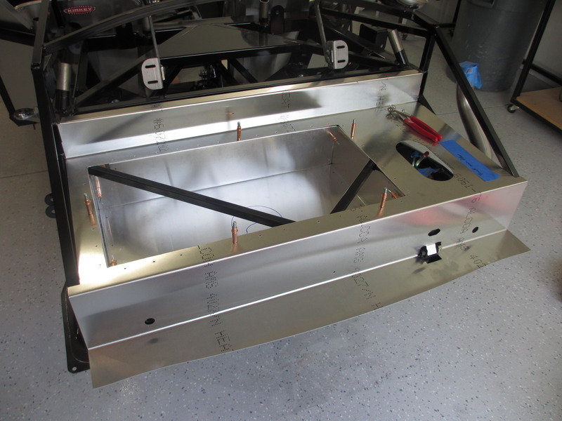
Next up was the fuel tank and trunk mods. I didn't feel like paying $150 for an FFR Metal kit so I just made up my own. Very simple to do. I had to wait for the tank and mounting hardware so I could get a measurement and figure out how deep I could go. 5 1/2" to the tank, so I went down 5" deep. Originally I was going to cut out the triangulation braces and expand the entire area by re-welding in new bracing but after looking at it with an engineer we decided it was best left alone. The design really is there for rear impact and energy transfer. There is a lot more going on then simple structure bracing, some areas are designed to fail while keeping other structure areas complete. Bottom line, safer to just let it be.
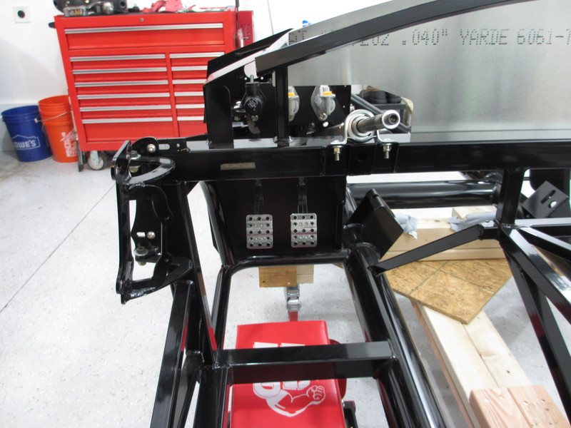
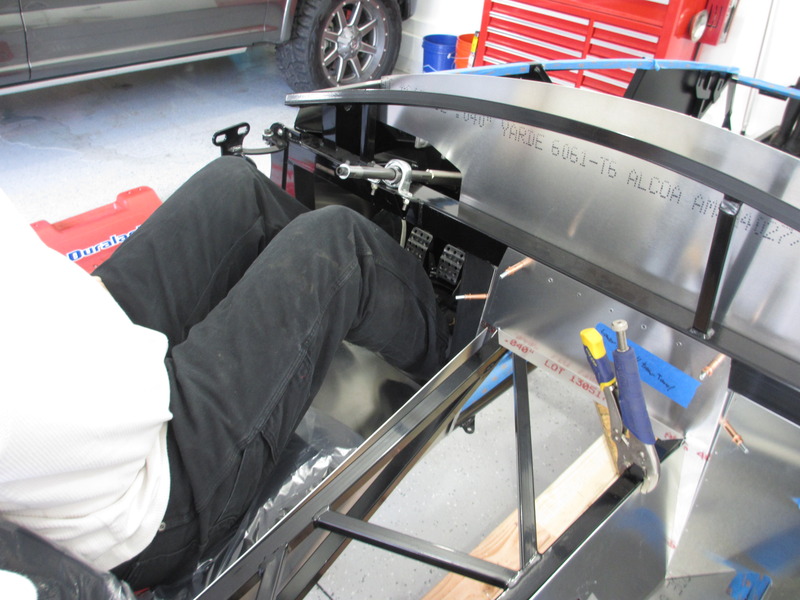
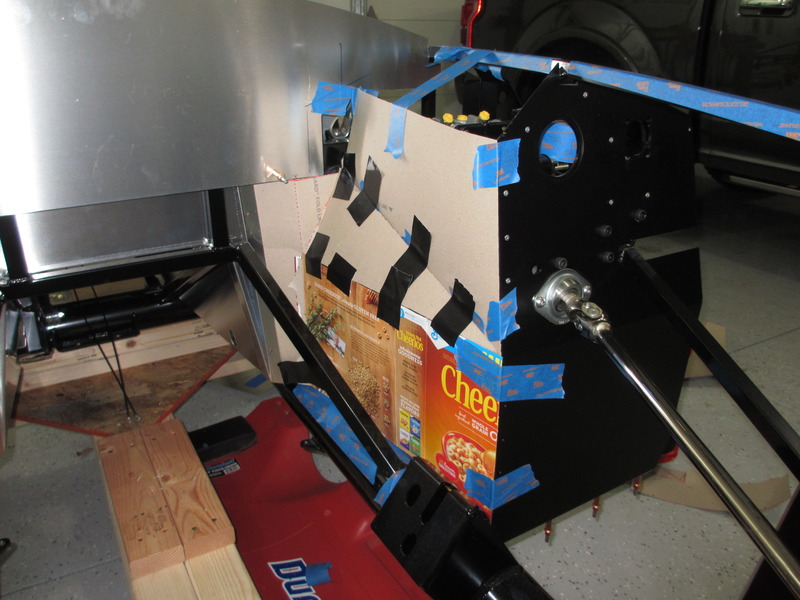
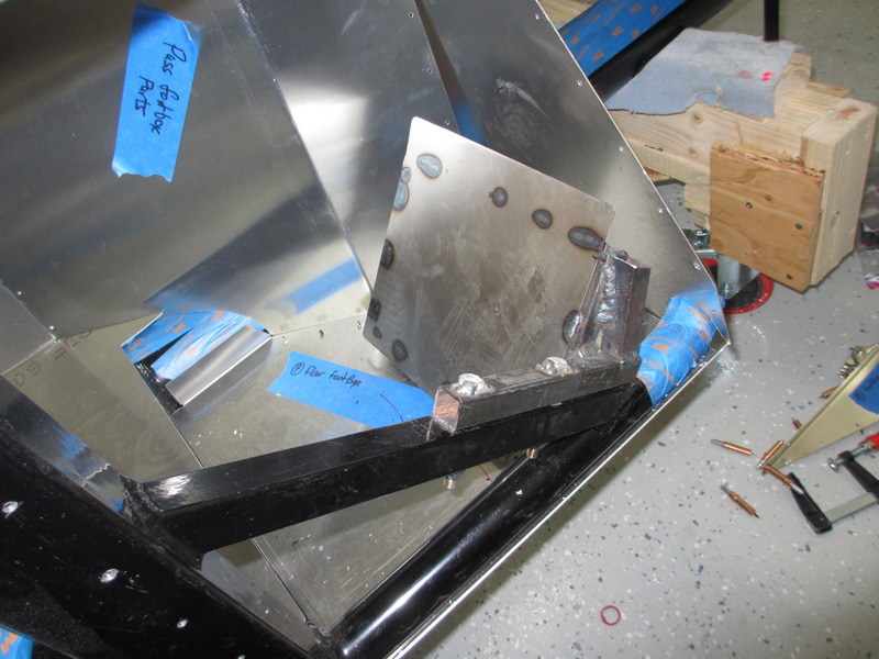
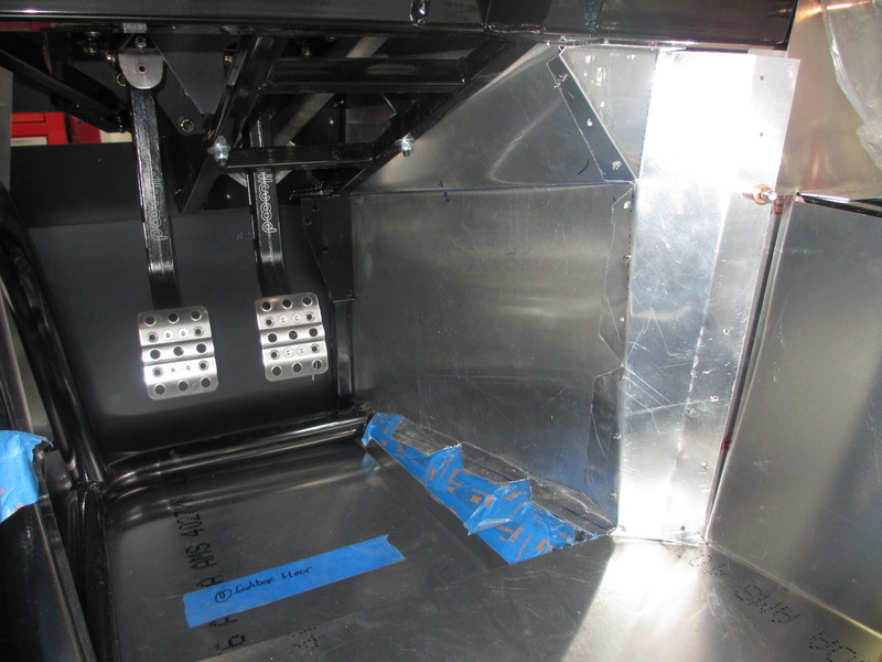
The driver foot box metal didn't take as long as I thought it would. I transferred my cardboard driver side foot box templates to 6061-T6 .04 aluminum sheet that I had bought. A little bending and cleaning up the edges resulted in a nice overall fitment. It's going to stay temporary until I get the motor in and see what my final spacing looks like. I'm very pleased with the additional gas pedal space that it provides.
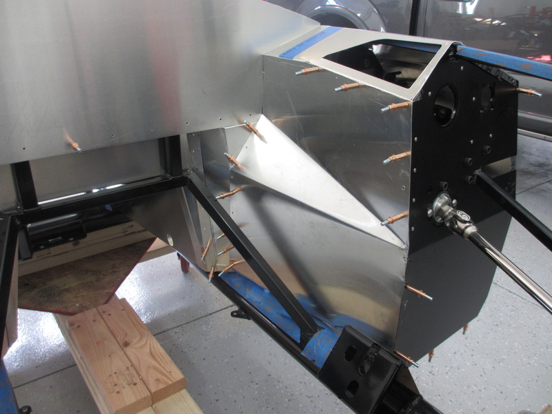
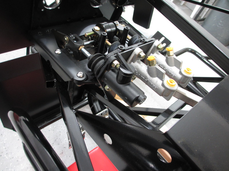
With some of the extra material laying around I made a quick bracket for the three fluid reservoirs. I'm running two for the master cylinders and one for the hydraulic clutch. I'm using the FFR provided units rather than the more conmanly used CNC reservoirs. I'm going to mount them using the bracket under the 3/4" tube in front of the driver side foot box, using larger rivets. Clean and simple. The bracket is 18g mild steel, with POR15 to help prevent paint damage if any brake fluid gets on it.
A driver side dead pedal was a must for me. One of the common instructions you receive at driving schools is to not rest your foot on the clutch or brake pedal when not in use. Drivers end up pushing the pedals in slightly causing unnecessary braking or clutch wear without realizing it. It took a little work to get it exactly angled where I wanted it but overall it should work perfectly. It will get the same grip tape treatment the passenger side received.
I got an email from Mike that my back ordered coyote ECU and wiring stuff is in, along with my fuel regulator. Next up should be a mock up fitment of the motor/trans, and wiring runs.
Last edited by Duke; 05-25-2018 at 08:29 AM.
-
Carl

Love the sheet metal work ...
Quick question: Did you expand out the DS outer foot box wall any to accommodate the dead pedal? I have on mine but I am not sure based on other posts that I will really have the room between the panel and the body.
Carl
Mk 4 Roadster
October 25, 2012 - Kit Arrives
April 8, 2013 - Build Starts
August 23, 2015 - Rolling Chassis/Engine & Transmission Installed
March 26, 2016 - Go Cart
-
Senior Member
No changes to the outside DS footwell. Totally stock. There is plenty of foot room and room for a dead pedal with the newer design.
-
Senior Member
Just a few updates this week. I received the correct third reservoir from FFR after sending back an incorrect one so I was able to build a quick bracket for the three of them. Two for the brakes, one for the hydraulic clutch. I had to do some digging to figure out the correct 90 deg elbow fittings but we're all set now. It's assembled and awaiting install. Levy confirmed he received my rear spindles and complete passenger side assembly so work is underway on the rear brake and bracket design for the 15" wheels. I pulled out the dash (covered dash with glove box option) and found a cut in it, so it was shipped back to FFR for a replacement. Front glass, CV joints, and some other back ordered and missing parts arrived from FFR as well. I believe I'm down to under 10 items now on back order.
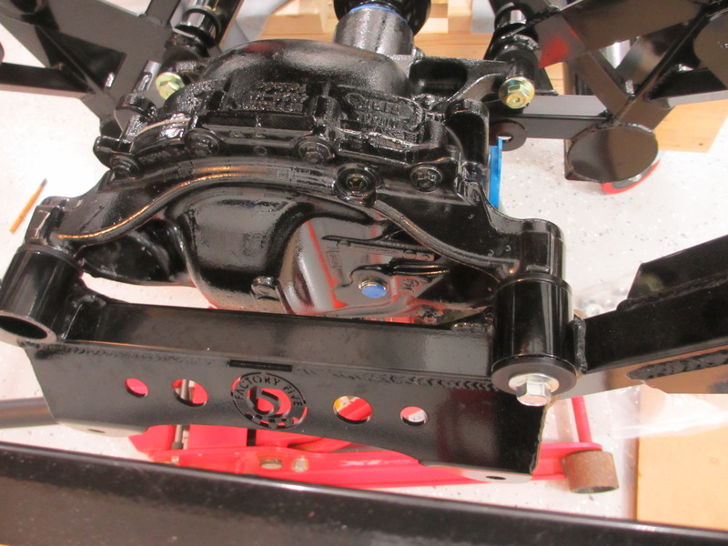
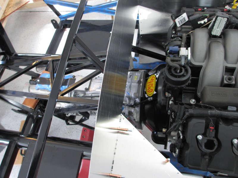
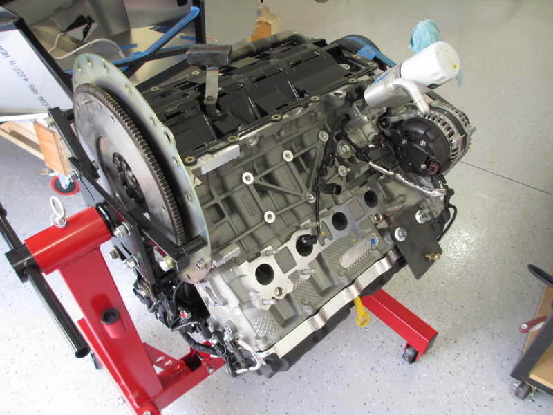
With most of the sheet metal done I now needed to do a motor/trans mock up. There's a few things I need to check, including my sheet metal work. Spacing on the T-56 mag, driveshaft length, and trans bracket mounting/modifications are just some of the items I'm probably going to have to check. Mike was kind enough to install everything on the coyote and T-56 mag before I picked it up so that saved me some time. Pulling it apart went quickly, but figuring out how to mount it on the engine stand took some time and a few trips to the part store for bolts and spacers. It all worked out though.
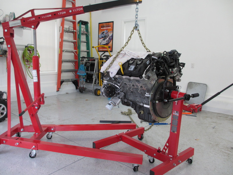
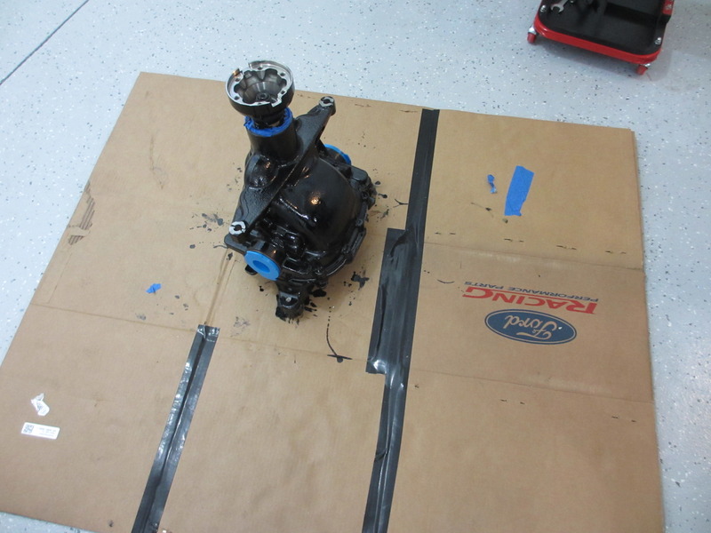
Moroso oil pan and energy suspension motor mounts went on without any drama. Just note it comes full of 8 qt. of oil. I'm planning on using it as break in oil so I saved it and added it back once the new pan was on. The new oil cooler needs to come off and a new oil adapter insert (pt # AL3Z-6890-A) is needed. Unfortunately like just about everything else, it's back ordered. Ford won't have them until mid April and there's not any aftermarket suppliers. I'm learning that times have definitely changed in the last 10 years since my other car builds with JIT manufacturing. Parts are mainly built just for the assembly line and not inventory. The only typical inventory stored now days are consumables. Even a lot of the after market are build to order. Margins really must be compressing. Anyways, pan off shot:
Last edited by Duke; 05-25-2018 at 08:29 AM.
-
Senior Member
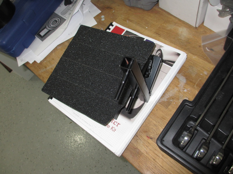
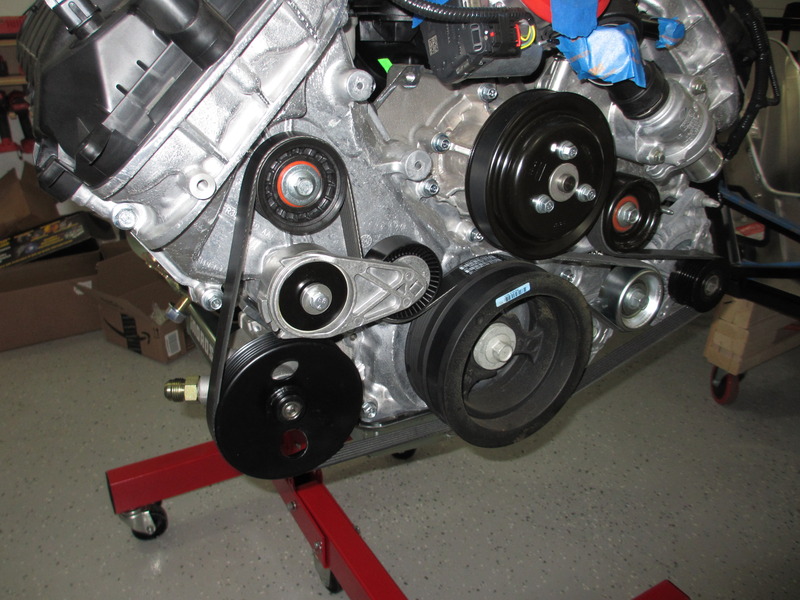
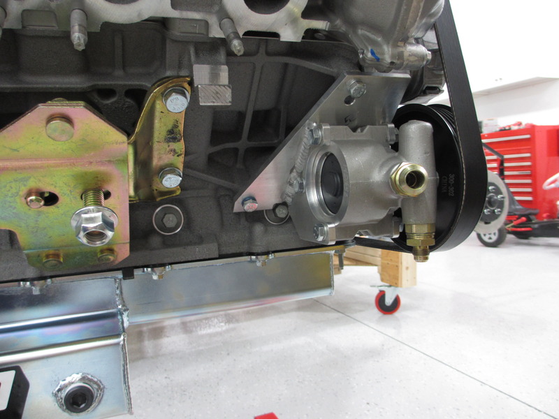
2015 Coyote Power Steering pump from Forte Parts Connection. I have to say, this setup is the best I've seen so far. Mike really nailed it with his kit. It's not on his website but he has them in stock. A few things that I really like about it is that you use all the stock locations on the block, the bracket is dead on perfect, he provides all the hardware needed, and explains over the phone exactly what you need to do to install it (swap the ribbed pulley off the tension arm and use the smooth one, see photos). The other nice part is that you have very easy access to the pump fittings, which has been a challenge from what I understand on some other kits. I'm into this just under $1,100 so far (including rack, reservoir, pump, pulleys, everything minus two hoses). Once I have the length and routing figured out Mike's going to get me what I need. One hint when putting this together. Don't try and bolt down the backwards idler arm under tension. Slide the belt off the pump pulley first, tighten the idler arm, then you can pull the idler arm back by hand (or lever) and slide the belt into place.
 ]
]
Last edited by Duke; 05-25-2018 at 08:29 AM.
-
Senior Member
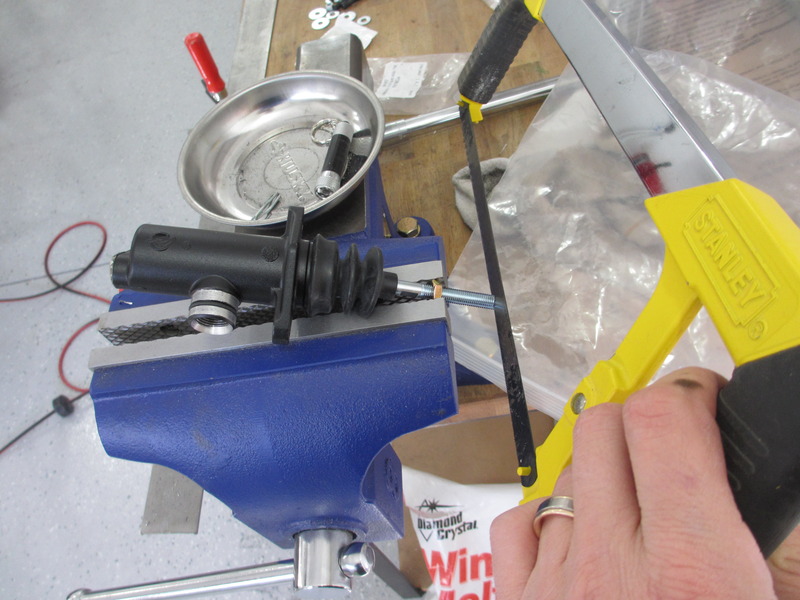
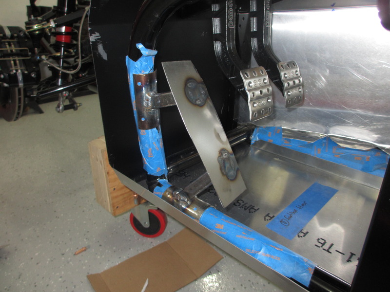
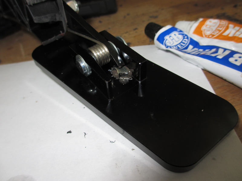
Coyote gas pedal. There's been a lot of discussion about this and many people opt for purchasing the ford van pedal. I was not really in the mood to spend another hundred on something I would have to modify anyways (and I'm already into this build $54,279.90 at present). I followed the FFR instructions to the letter and I'm okay with the mounting. Here's how it came out after first pass. There are some issues (more on that below) and how I solved it.
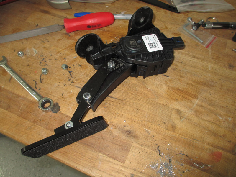
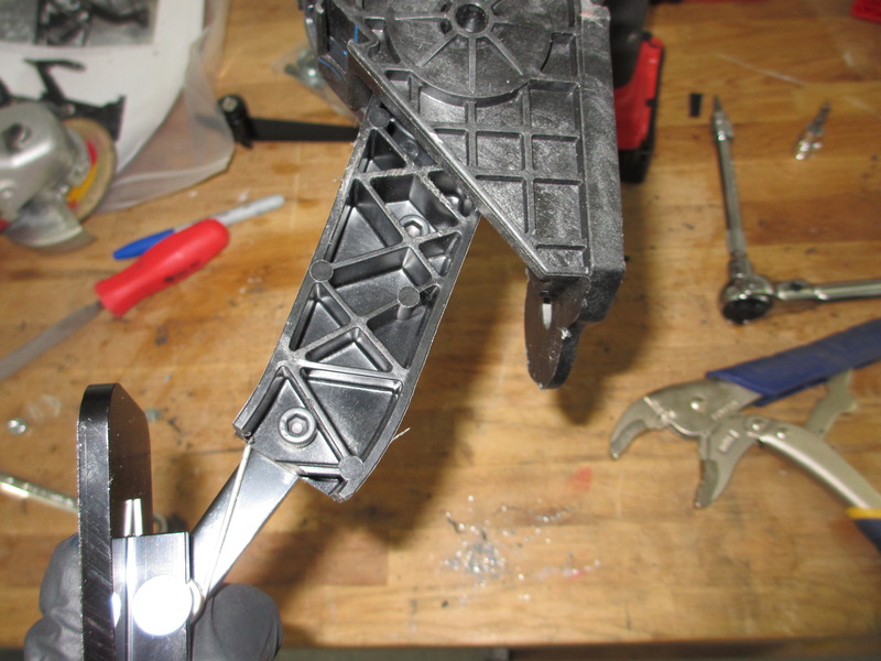
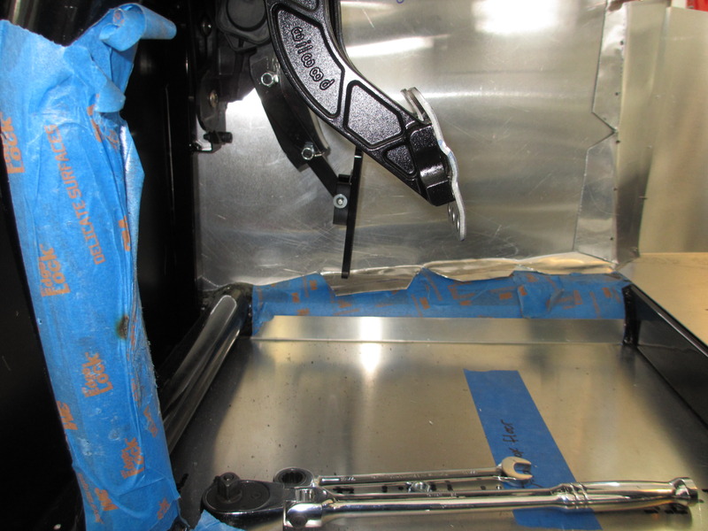
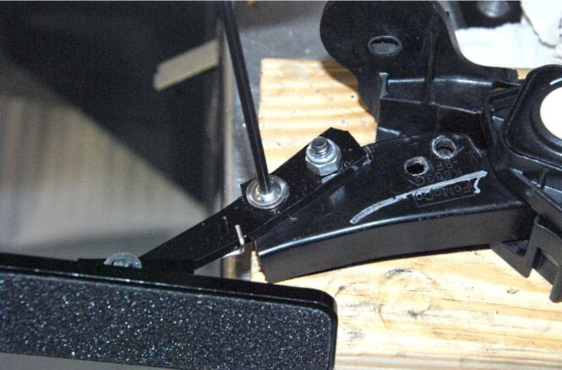
The huge mustang pedal that comes with the wiring harness kit has 3" of travel from end of pedal to fully depressed. Once it's cut and the FFR pedal is grafted onto it the length decreases to 2 1/8". Acceptable, but a little sensitive. From the center mount of the pedal it's about 1 5/8" total travel. Now, FFR says there is about 2 1/4" of brake pedal travel before you are really on the brakes hard. That feels about right when I move the pedal and measure it. From this point I want to be able to correctly heal-toe for track driving so getting the gas pedal in the correct position is very important. In terms of overall depth related to the brake and clutch pedal I think I nailed it. Right at about 2 3/8". The problem comes with the FFR pedal. As you can see from the pictures below it's at a 45 degree angle from where your foot would naturally be. The spring pivot arm on the pedal doesn't help it either since you don't really have the feel of if you are pushing in the pedal or just rotating the pedal on the spring arm. Not a good setup. In the pictures below you can see how it is by the book, where it needs to be (with my hand holding it), and how FFR solves the problem. The FFR image is actually out of the instruction manual and you can see they removed it from the upper holes, cut it down further, and then remounted it with two smaller holes close together and a steeper angle. I'm not a big fan of this approach as it changes the distance (reduces it) between the brake pedal depressed and the gas pedal, it also is less support for the grafted pedal. If I were to go this route I would have rather made a sister bracket to give it more support.
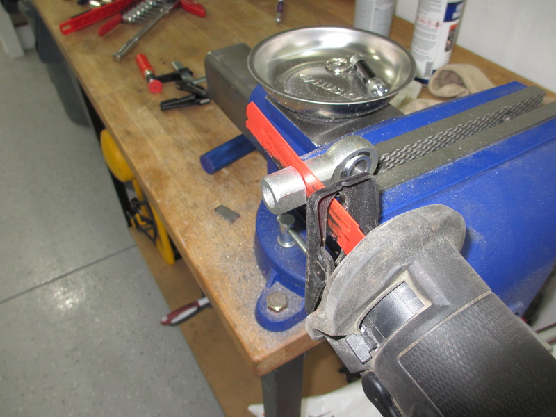
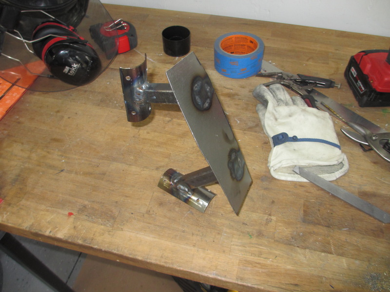
FFR's manual image:
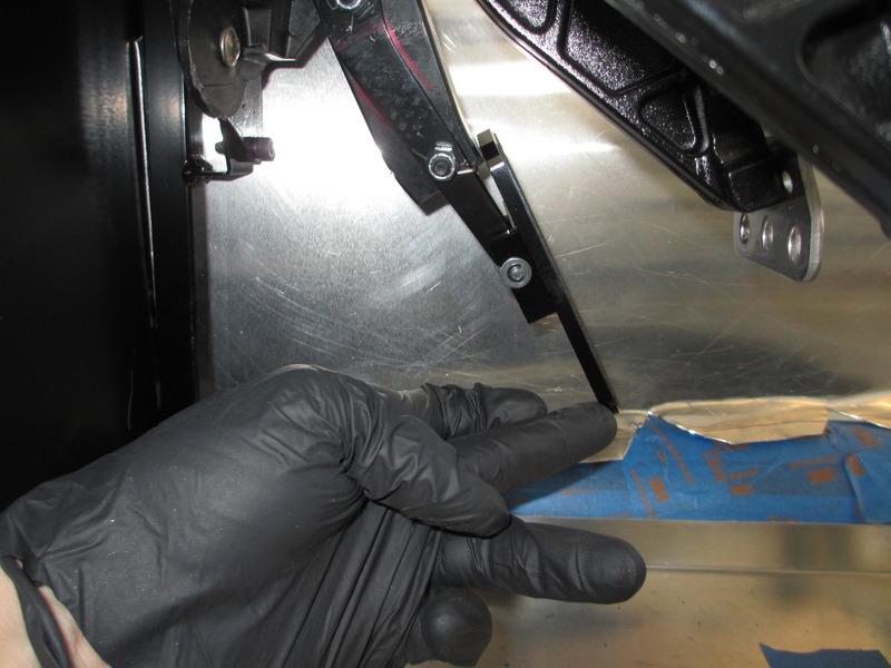
After taking apart the pedal and thinking about it for a little while I came up with a simpler solution. I cut down a thick spacer washer, ground it down to the thickness I wanted, and then ground down the paint to get to the raw aluminum for a good bond. With a little JB weld we now have a stop affixed to stop the pedal from traveling with the spring retainer. It now stays in the exact position where I was holding it above with my hand. My mock up put the pedal right in the sweet spot for heal-toe. Now, I'm sure with my luck I'll probably have to 'refine' it once I get it on the track (i.e. pull it all out and redesign it) but for now it should work perfectly.
Last edited by Duke; 05-25-2018 at 08:30 AM.
-
Senior Member
-
Senior Member
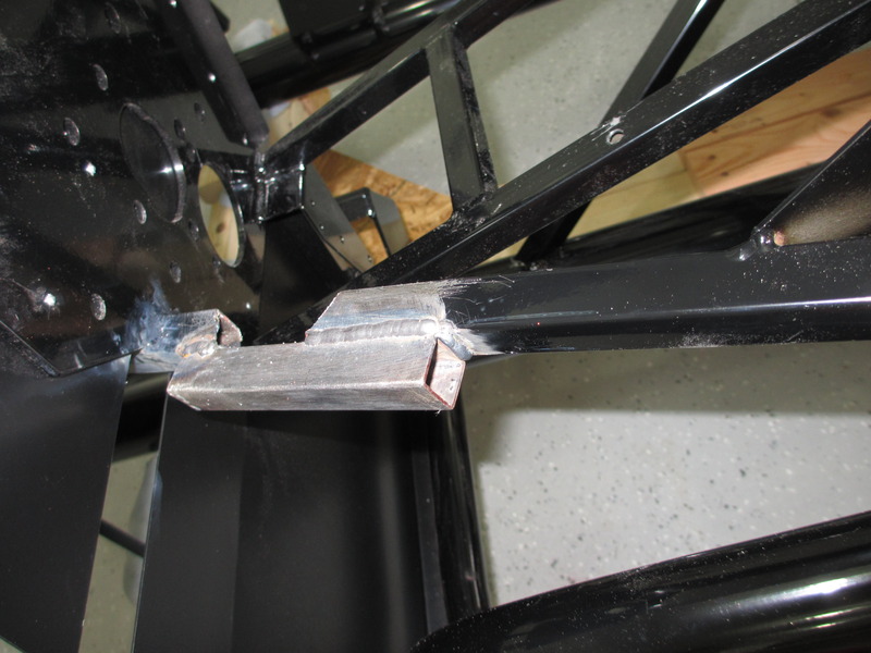
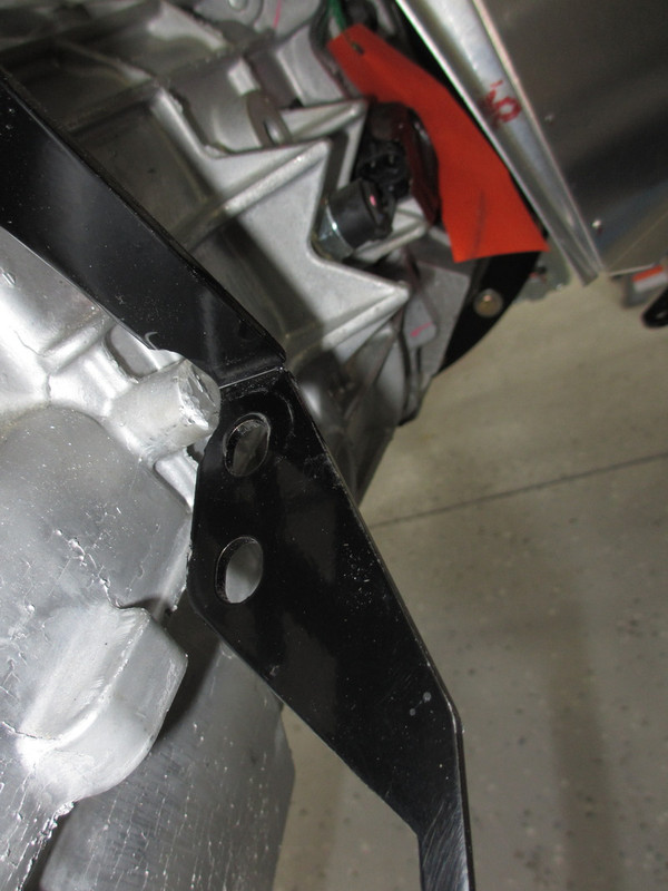
Interesting update. That T56 is pretty huge. You're right, I think the driveshaft could be challenging. When you calculated the length, did you allow for the approx 3/4 to 1 inch the slip joint will be exposed when it's installed? That's the distance needed to get the driveshaft to swing into the diff mount. Might be even a little more with the driveshaft so short and the resulting sharp angle when installing. There's a similar boss on the side of the TKO right near the e-brake, and I believe others have trimmed it without issue. Looks like the stock location for your e-brake is going to be really tight. Are you planning to install it there, or doing something different? Still trying to understand FF's recommendation and practice of only one engine mount spacer. Mine is level with a spacer on both sides, as I said in your other thread.
Build 1: Mk3 Roadster #5125. Sold 11/08/2014.
Build 2: Mk4 Roadster #7750. Sold 04/10/2017.
Build Thread
Build 3: Mk4 Roadster 20th Anniversary #8674. Sold 09/07/2020.
Build Thread and
Video.
Build 4: Gen 3 Type 65 Coupe #59. Gen 3 Coyote. Legal 03/04/2020.
Build Thread and
Video
Build 5: 35 Hot Rod Truck #138. LS3 and 4L65E auto. Rcvd 01/05/2021. Legal 04/20/2023.
Build Thread. Sold 11/9/2023.
-
Senior Member

Great build going Duke.
I too only had to use a single spacer on the DS mount. Engine level????? who cares. No one will know if its off by 1.236 degrees.
You said you are waiting for back ordered FFR headers. Consider the extra few hundred and get the Stainless Headers for the Coyote. You'll absolutely love these things and engine will breath considerably better.
-
Senior Member
Thanks, but I'm going under car exhaust. No need to spend 1200 on headers just to cut them up
-
Senior Member
Originally Posted by
edwardb
Interesting update. That T56 is pretty huge. You're right, I think the driveshaft could be challenging. When you calculated the length, did you allow for the approx 3/4 to 1 inch the slip joint will be exposed when it's installed? That's the distance needed to get the driveshaft to swing into the diff mount. Might be even a little more with the driveshaft so short and the resulting sharp angle when installing. There's a similar boss on the side of the TKO right near the e-brake, and I believe others have trimmed it without issue. Looks like the stock location for your e-brake is going to be really tight. Are you planning to install it there, or doing something different? Still trying to understand FF's recommendation and practice of only one engine mount spacer. Mine is level with a spacer on both sides, as I said in your other thread.
Yea, that's my current challenge. I'm going to talk with a few local drive line places and get some opinions. It's 8 3/4" from trans housing to IRS pumpkin mounting surface and 8 1/4" from trans input shaft to IRS mounting surface. As it stands the body of the drive shaft would be about 1/2" of 'tube' before the weld points on the joints. Assuming it's just two joints welded together that wouldn't give me enough room to slide it in/out which would mean I would have to install it with the motor/trans as one unit. That's the worst case at the moment. I'm hoping there are some shallow joints available on the market that would give me a little more space. I'm sure there is a solution out there.
E-brake is not a big deal. I can modify and redesign as needed on that. Last email from Levy was that he is possibly looking at a hydraulic parking brake setup anyways. If we end up going that direction then all bets are off and I'll be making something anyways. 15's on the new IRS is just one of another set of problems that will be solved during this build.
Oddly enough, I did a few measurements and level markers on the motor with only one space and it all appears to be level. Maybe it's not enough either way to be measurable. Who knows. At this point I'm just going to go with it assuming they have and enough CAD design sessions to get it right and with or without a spacer is fine.
-
Senior Member
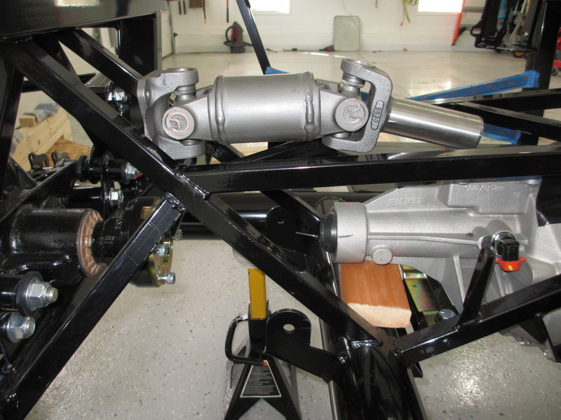
Quick update, I found a kick @ss drive line shop locally that will have my new drive shaft made up by tomorrow. They are literally machining down the two joints and welding them together, then balancing it. That includes 3/4" split joint spacing, however I'm not sure if that's enough to get it in without lifting the motor & trans. I'll do a full post when I have it back.


 Thanks:
  Likes:


 Reply With Quote