-
Senior Member


Originally Posted by
russelljones48

Boy am I glad you're ahead of me. Great help on the DBW pedal. Looks great, relatively easy to duplicate (my fabrication skills are minimal) and should be very functional. I have a couple of favors to ask. Once you're sure the engine hoist plates work would you post pics? and I can't quite see enough of the wooden engine stand to duplicate it. When the engine is next off the stand could you post some pics of that too? DO you think the stand could be placed or mounted on a cheap dolly and work OK? THANKS
Sure, I'll post some pics of each after the engine is installed. My inspiration for the lifting hooks was mainly from this post on the other forum. Mine don't quite look like these, but are similar in function and attach to the same places. http://www.ffcars.com/forums/2766120-post3.html. Yes, the engine stand could be put on a regular dolly or wheel dolly. I've done both in the past.
Build 1: Mk3 Roadster #5125. Sold 11/08/2014.
Build 2: Mk4 Roadster #7750. Sold 04/10/2017.
Build Thread
Build 3: Mk4 Roadster 20th Anniversary #8674. Sold 09/07/2020.
Build Thread and
Video.
Build 4: Gen 3 Type 65 Coupe #59. Gen 3 Coyote. Legal 03/04/2020.
Build Thread and
Video
Build 5: 35 Hot Rod Truck #138. LS3 and 4L65E auto. Rcvd 01/05/2021. Legal 04/20/2023.
Build Thread. Sold 11/9/2023.
-
Senior Member

Quick IRS Update
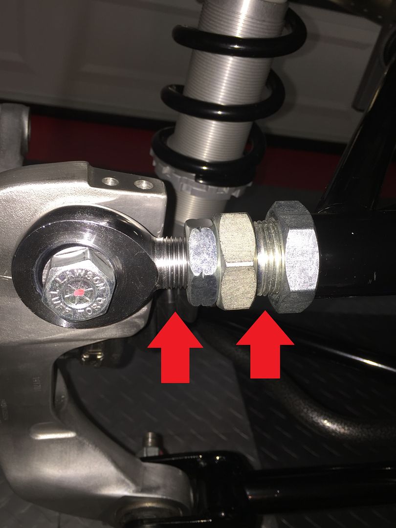
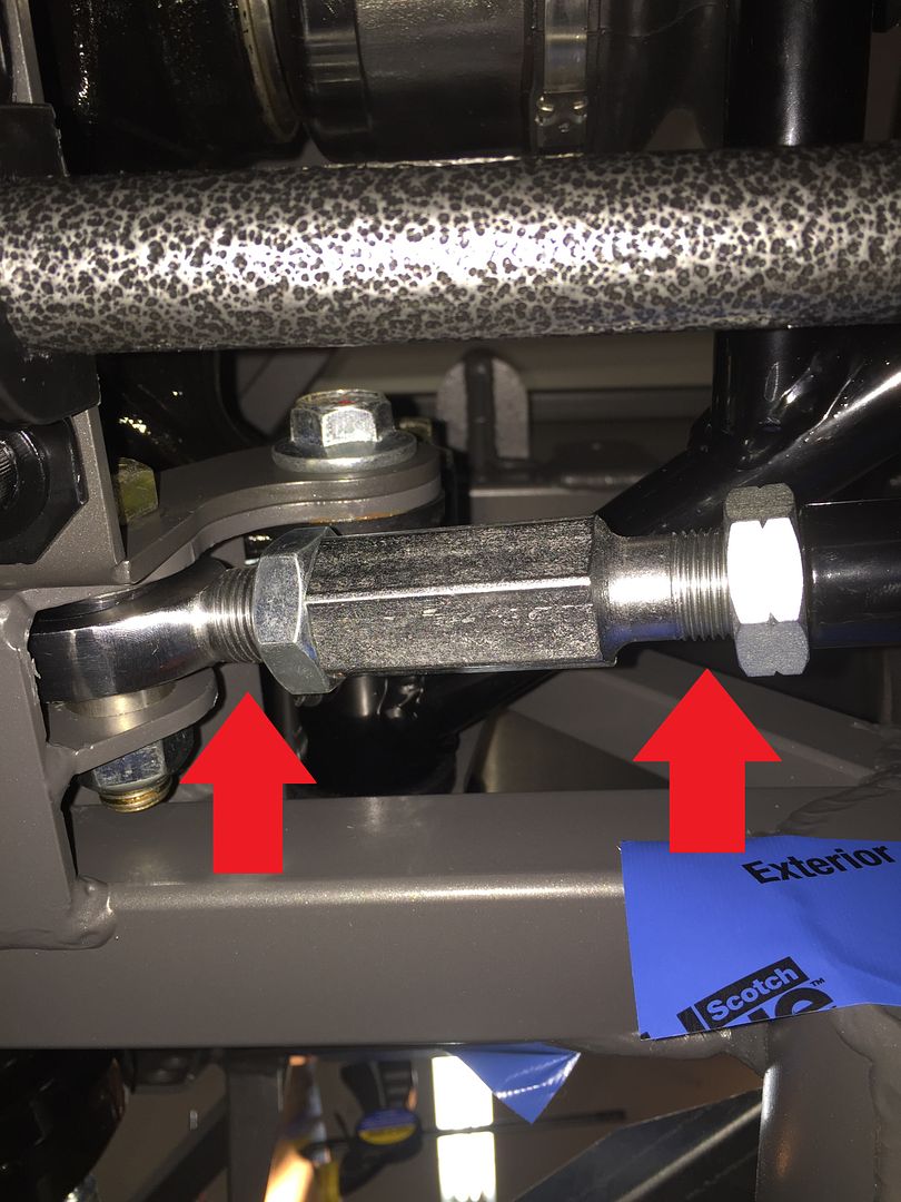
I know some are following this thread because of the new IRS setup, so thought I would pass this along. Yesterday afternoon I got a little bored (OK, both of my football teams were losing badly...) so I decided to play around with the IRS alignment. Just to get it somewhere in the ballpark. Used a level on the hubs for camber and a laser level pointed toward the front of the car for toe. Like I said, really rough. They were clearly way off from the original assembly. What I discovered is now quite obvious in hindsight, but I missed it during the initial assembly and I don't remember it from the instructions. It it's there, I obviously overlooked it. For the two adjustment points on each side, it's necessary to have equal threads showing on both sides before you bolt in the heim joint. I had the toe adjustment pretty centered, but that was mostly by accident I guess. For the camber adjustment, I had the fitting almost all the way into the UCA, but then the heim joint only about halfway in. So it was impossible to adjust it properly. I had to remove the large bolt holding the joint to the knuckle, center things up, and re-torque the bolt. Now it works perfectly. In both cases, you loosen the jam nut on each side and rotate the center adjuster as required. Then tighten the jam nuts. That's it. No dis-assembly required.
Here are a couple of pics. Camber adjustment showing equal threads on both sides now:
Toe adjustment showing roughly equal threads on both sides. Note where I have these as pictured is roughly to the spec. Looks like plenty of adjustment still available either way, and plenty of thread engagement. Also note, not surprisingly, the adjustments interact with each other. Adjusting camber also affects toe. Adjusting toe also affects camber. I'm planning to have the car professionally 4-wheel aligned when the time comes.
Last edited by edwardb; 05-31-2016 at 06:54 AM.
Build 1: Mk3 Roadster #5125. Sold 11/08/2014.
Build 2: Mk4 Roadster #7750. Sold 04/10/2017.
Build Thread
Build 3: Mk4 Roadster 20th Anniversary #8674. Sold 09/07/2020.
Build Thread and
Video.
Build 4: Gen 3 Type 65 Coupe #59. Gen 3 Coyote. Legal 03/04/2020.
Build Thread and
Video
Build 5: 35 Hot Rod Truck #138. LS3 and 4L65E auto. Rcvd 01/05/2021. Legal 04/20/2023.
Build Thread. Sold 11/9/2023.
-
Thanks - the other post gives me a good idea of what's needed. Looking forward to more on your build. Do you have maker and part number for the clutch switches?
RJ "A race car exists in only two states: broken or in the process of becoming that way" Road and Track, May 2015
-
Senior Member

Engine In
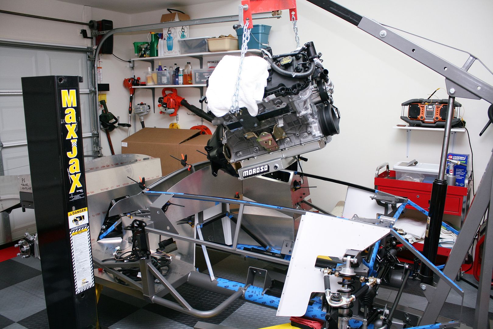
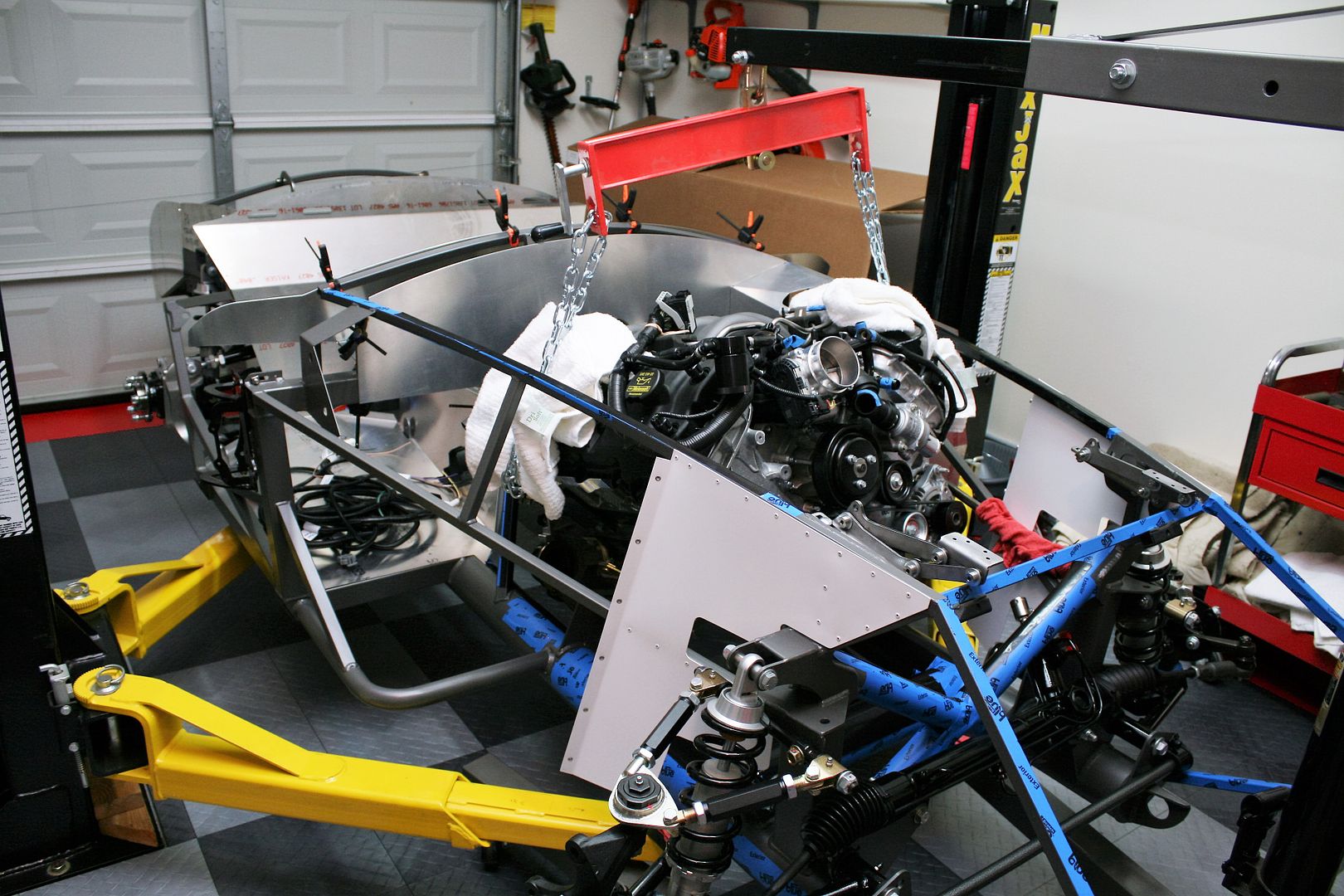
Late yesterday I dropped the Coyote into the chassis for the first time. Hanging over the engine compartment, my first impression is there’s no way that thing will fit in there. But it does! Went it with relatively little drama. This is just a mock-up, so in some ways not completely how it will be when I do the “real” installation. The engine had the bell housing but no transmission. The DS footbox was just set in place, and no PS footbox yet. Next time around it will be different, and I won’t be doing it alone. But based on this first experience, I think it will be OK. I guess I shouldn’t say I was alone. My longsuffering wife helped by keeping it from swinging around, and being another set of eyes as we lowered it into place. I kept my promise of no heavy lifting!
What I learned. The engine hooks I made will be fine. Front DS is wide open. The PS rear can’t be in the back cylinder exhaust header holes, but one forward. Then it will clear the PS footbox. The steering column needs to be swung out of the way to clear the alternator going in. I just loosened all the set screws, pulled it off the steering column, and swung that end over. The 2bking modified panels on the DS are awesome. Wow, what a great job he did on those. The head sits in the DS footbox perfectly, and the restored space for the driver’s feet below is outstanding. FF needs to make this a standard for the Coyote builds. Completely removes one of the major objections. I was thinking of doing an expanded footbox on the PS. But the gained space isn’t that much, and the factory pieces I have already are powder coated with the anniversary white PC. I’m going to use them as is. I used Whitby spacers on both motor mounts. Both motor mount bolts are in the bottom of the slots, and the engine is relatively level. I will be leaving both in. I have the engine blocked at 2 degrees down measured off the dampener, roughly what I expect it will be when the transmission is installed and pinion angle set. The Moroso pan is slightly above the frame rails in the front, and just flush or very slightly below in the back. Fine with that. The Quicktime bell housing does extend a little lower than the pan on the bottom circle. I would say about 1/2 inch. I will probably go ahead and trim that off. But honestly if I get in a situation where I hit that, I’m probably hitting something else too. We’ll see. Also confirmed the shorter/compact oil filter clears the 4 inch chassis tube just fine. No remote oil filter to install. Fine by me.
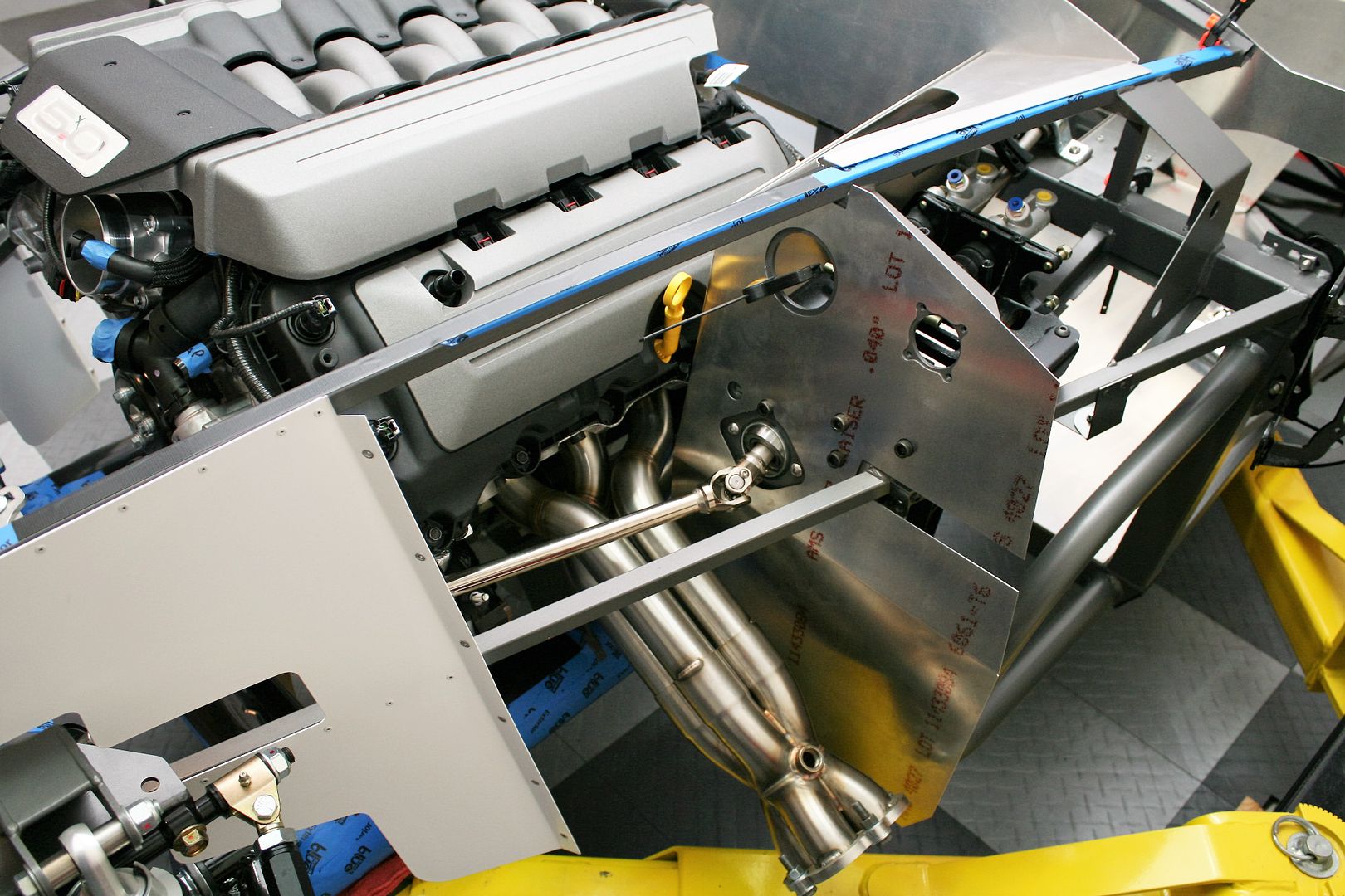
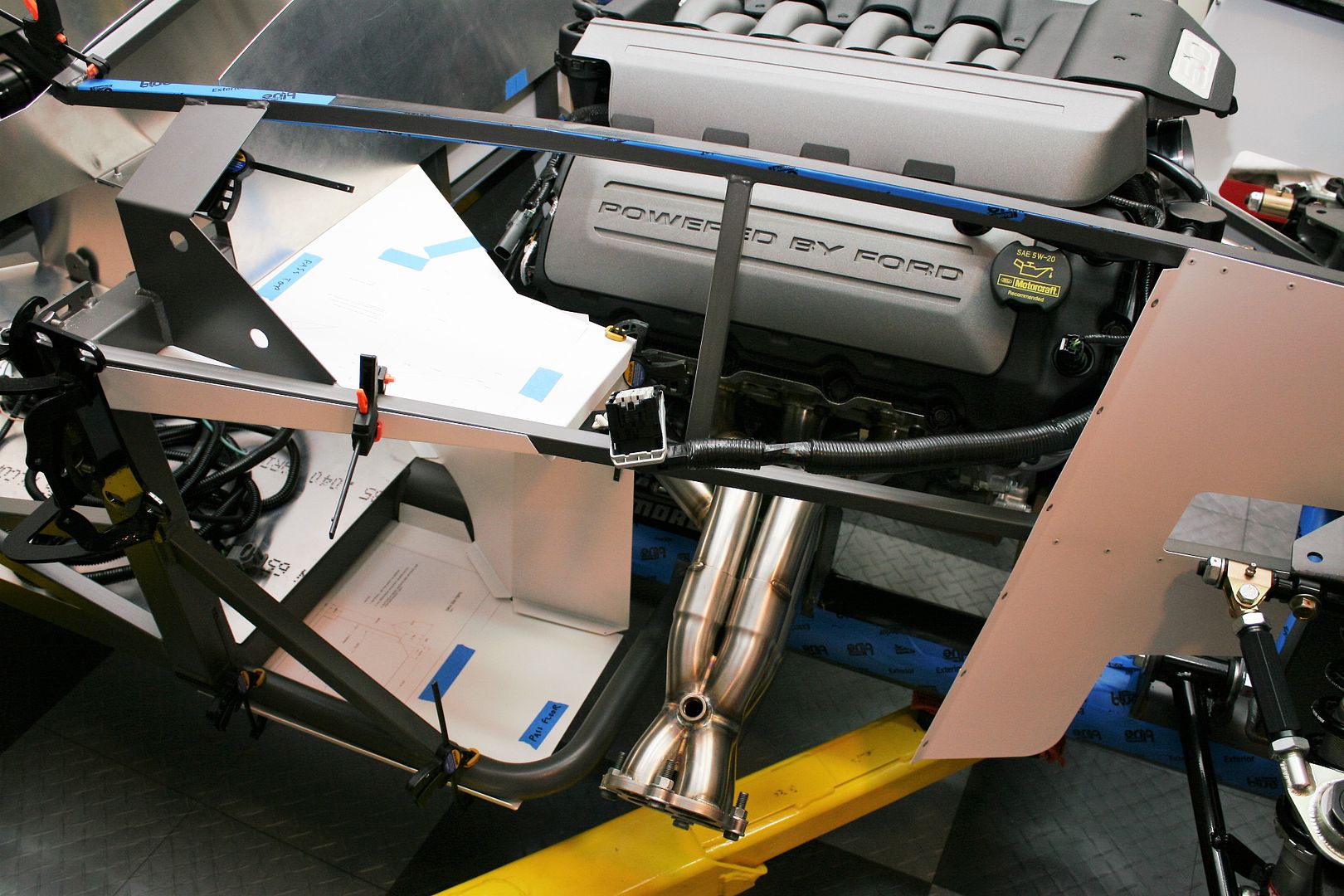
I bolted in the stainless headers. PS, obviously especially without the footbox there, was wide open and easy as can be. Note to self. Get all the bolts started before tightening any of them! Even finger tight. The header flange is very precise. Now the DS is another whole story. I was able to get 4-5 of them on with a little effort, but there are a couple that are nearly impossible. I’ve read about this, and my experience is quite typical. Some guys put an access panel in the footbox, but for now I’m not planning to do that. My thought is for the hard to reach ones to use studs vs. the allen head bolts I'm using everywhere else. I think I’ve read where others have done this as well. Assuming there’s enough room to get the header into the opening and hooked over the studs. Another thought, which I’m seriously considering, is to install the DS header during engine installation. Once the engine is low enough that the header can go under the 3/4 inch frame tube, go ahead and install the DS header while more accessible. Using a combination of bolts and studs, still would able to re-torque the bolts later if necessary after a few run cycles. But anything more may require loosening the engine mounts and lifting the engine. Not something I want to think about, but not unlike many regular production cars. I’m planning to use Remflex gaskets, and I’ve had great luck with those. Both of my former builds haven’t needed the exhaust headers touched after the initial installation. Hopefully my luck will hold.
I also test fit the Gas-N side pipes. Wasn’t particularly easy because how I have the frame sitting on my 2-post, the pipes hit the side arms. So I had to lift each side to check them. But I wanted to get a sanity check on what pipe alignment looked like. I’ve had to work with this a lot on my previous builds, and many can cite how this aspect has kept them awake at night. I’m happy to report it looks pretty good. The ends of the Stainless headers exit the frame area at nearly the exact location on both sides and the pipe alignment seems OK. Both pipes will likely take a little bit of wedge to get parallel to the body. The DS more than the PS. This will all be finalized later during body installation. But I’m very satisfied with this initial check.
Here are some pics of the engine install. Engine hovering over its intended destination:
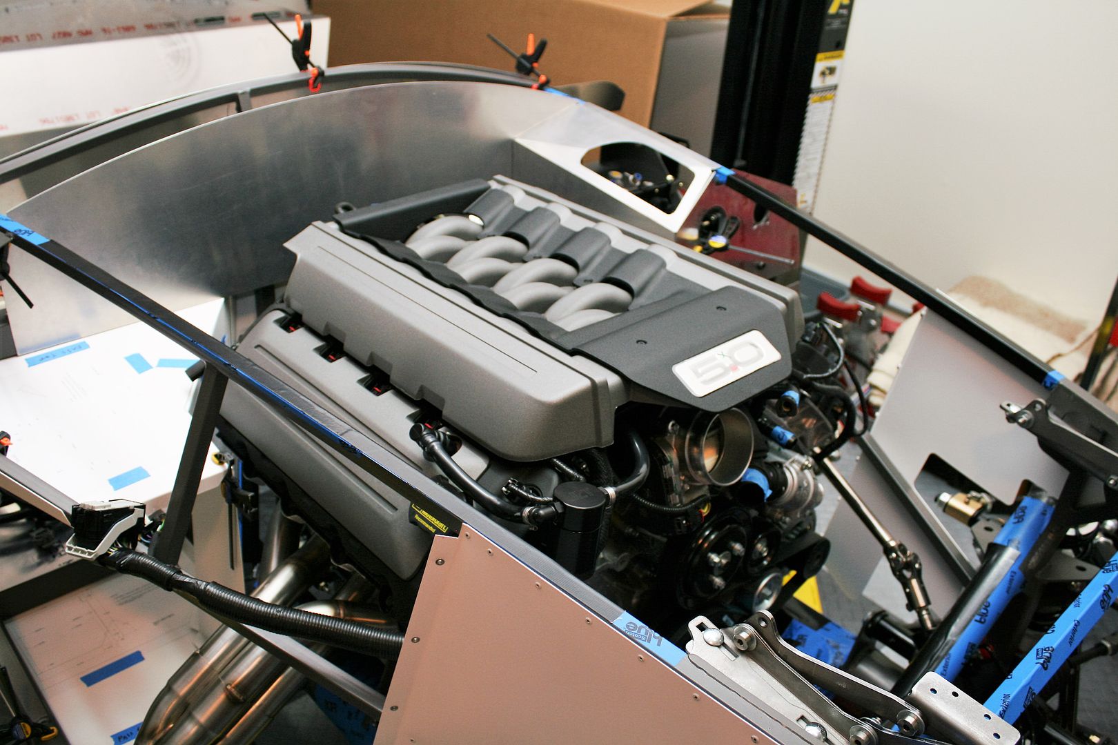
Settling in:
All in. Note these are the newer style 2015-2016 covers. A little chunky looking compared to the previous style, but they’re growing on me. I think they’re a little different around the back with the new CMCV setup on this engine.
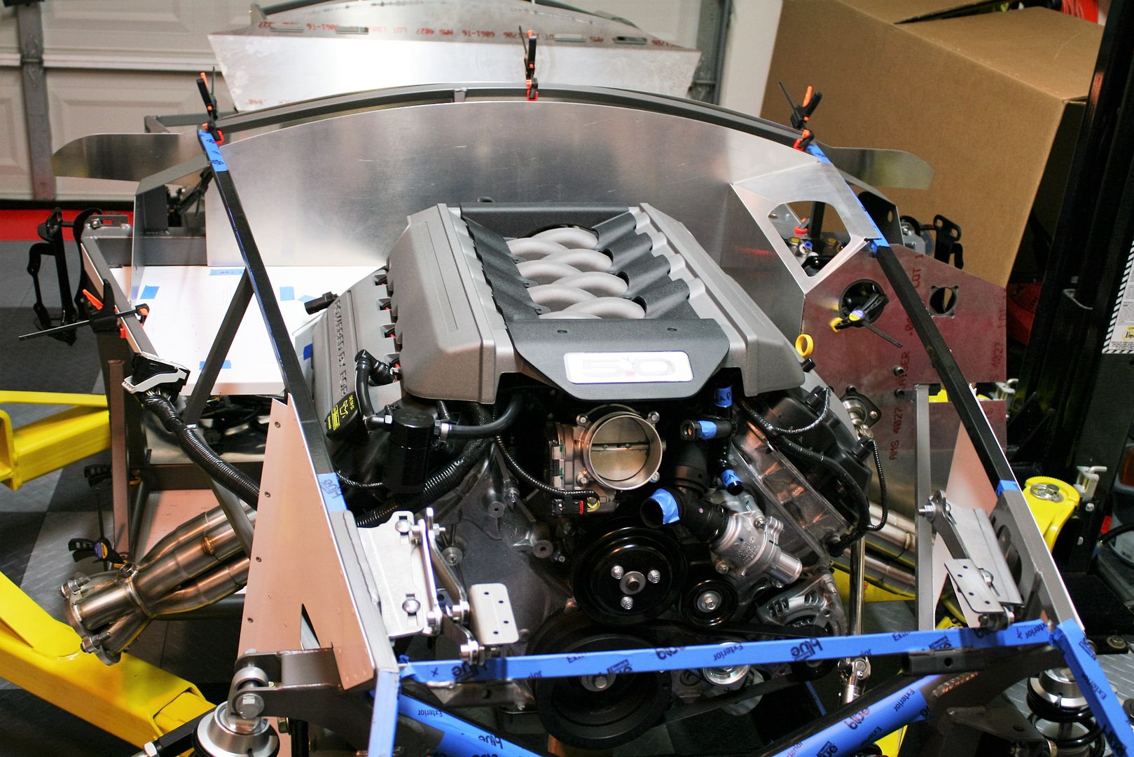
DS stainless headers, after some “minor” frustration getting most of the bolts in.
PS stainless headers. Also checking the fit and clearance of the PS footbox pieces. All good.
Last edited by edwardb; 10-27-2015 at 05:36 PM.
Build 1: Mk3 Roadster #5125. Sold 11/08/2014.
Build 2: Mk4 Roadster #7750. Sold 04/10/2017.
Build Thread
Build 3: Mk4 Roadster 20th Anniversary #8674. Sold 09/07/2020.
Build Thread and
Video.
Build 4: Gen 3 Type 65 Coupe #59. Gen 3 Coyote. Legal 03/04/2020.
Build Thread and
Video
Build 5: 35 Hot Rod Truck #138. LS3 and 4L65E auto. Rcvd 01/05/2021. Legal 04/20/2023.
Build Thread. Sold 11/9/2023.
-
Senior Member

Engine In (continued)
This afternoon I starting playing with some of the control pack components, trying to decide where best to locate things. Still way more planning and work to do here, but here’s a couple first shots. Based on where the main harness comes off the engine (I think the same as the 2011-2014 engine) and the length of that harness, the PCM has to go alongside the engine. No way it will reach the firewall or even PS footbox as some have done. This location for the PCM allows the engine harness and then also the control pack harness to plug in reasonably OK and look decent from the engine side. I tried every possible angle, location, upside down, right side up, multiple cable routings, etc. This seems about the best. I will need to design and fabricate some type of tray for the PCM to set in. I wish it could be further from the headers, because I have to think there’s going to be a little more radiated heat there than elsewhere. But I don’t see where I have a choice. The PCM case has what looks like heat fins on one side, and those aren’t facing the headers. So if I shield the other side some – while still allowing airflow all around it – I think it should be OK. It’s designed to work in the harsh underhood environment, but don’t want to heat it unnecessarily.
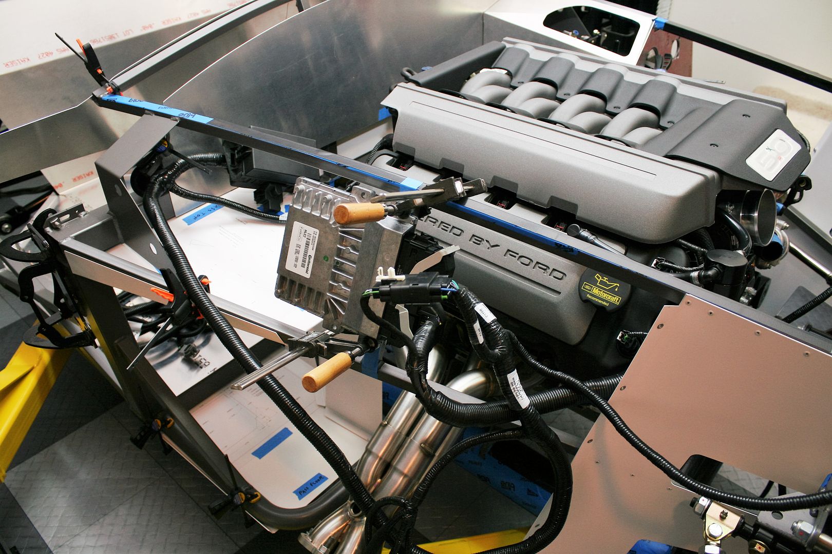
I’m thinking the power distribution box will be somewhere in this area on the firewall. It’s just too big to fit behind the dash. I’m not planning a heater – only heated seats like I’ve done before – so I have some flexibility of where to place it on the firewall. My only concern will be the wiper motor, and that’s pretty flexible. With the box in this location, the large bundled harness back to the PCM is still a bit too long, but I can deal with that in the fender well area I think. I may have to adjust the lengths a bit on a couple of the cables that go into the dash area. But that’s not something I have any qualms about doing and the smaller cables only have a few conductors.
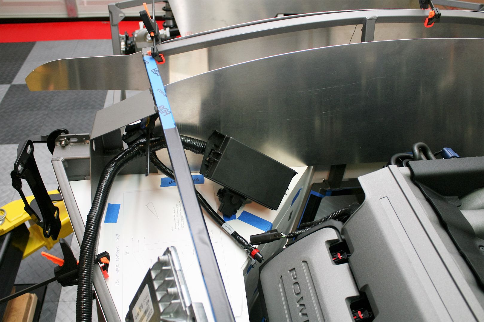
I still have a lot of studying and thinking to do about joining the control pack wiring into the RF harness and main power wiring. The control pack came with a bunch of big power wires, including the main alternator charging wire, starter power wiring, etc. It’s not just clear to me why I would need to do those differently than I have in the past with the RF harness. As long as I have the always on connection from the battery to the main power input on the power distribution box, I think I have the power covered. And obviously the control pack has its own wires to the starter, ignition switch, cooling fan, fuel pump, etc. But need to spend more time with this. It’s definitely different than the previous version.
Still to be checked out are the intake, radiator and cooling lines, radiator reservoir, power steering lines and reservoir, brake and clutch reservoirs, fuel lines and regulator, and a decision about battery location. Still going back and forth between the Breeze front mount and the FFMetals under trunk mount. There is a lot going on in there. Still having fun though!
Last edited by edwardb; 10-27-2015 at 05:39 PM.
Build 1: Mk3 Roadster #5125. Sold 11/08/2014.
Build 2: Mk4 Roadster #7750. Sold 04/10/2017.
Build Thread
Build 3: Mk4 Roadster 20th Anniversary #8674. Sold 09/07/2020.
Build Thread and
Video.
Build 4: Gen 3 Type 65 Coupe #59. Gen 3 Coyote. Legal 03/04/2020.
Build Thread and
Video
Build 5: 35 Hot Rod Truck #138. LS3 and 4L65E auto. Rcvd 01/05/2021. Legal 04/20/2023.
Build Thread. Sold 11/9/2023.
-
Senior Member


Originally Posted by
russelljones48

Boy am I glad you're ahead of me. Great help on the DBW pedal. Looks great, relatively easy to duplicate (my fabrication skills are minimal) and should be very functional. I have a couple of favors to ask. Once you're sure the engine hoist plates work would you post pics? and I can't quite see enough of the wooden engine stand to duplicate it. When the engine is next off the stand could you post some pics of that too? DO you think the stand could be placed or mounted on a cheap dolly and work OK? THANKS
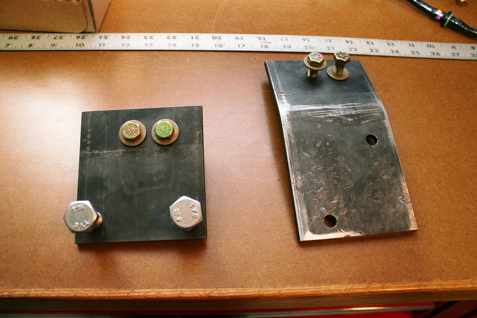
Here are the pics you requested. The plates were made from a 4 x 12 inch piece of 1/4 piece of steel from Lowes. Cut it, drilled some holes, and beat on it for a while in my bench vise to get the necessary bend in one. You can see the scars. In hindsight, maybe I could have used some heat and it would have bent easier. But it's done now. The one on the left is for DS front, and bolts into two factory lift points. The one on the right is for PS rear, and bolts into either of the two rear exhaust header bolt pairs. I drilled two holes for the chain attachment. For safety plus to adjust the balance if needed.
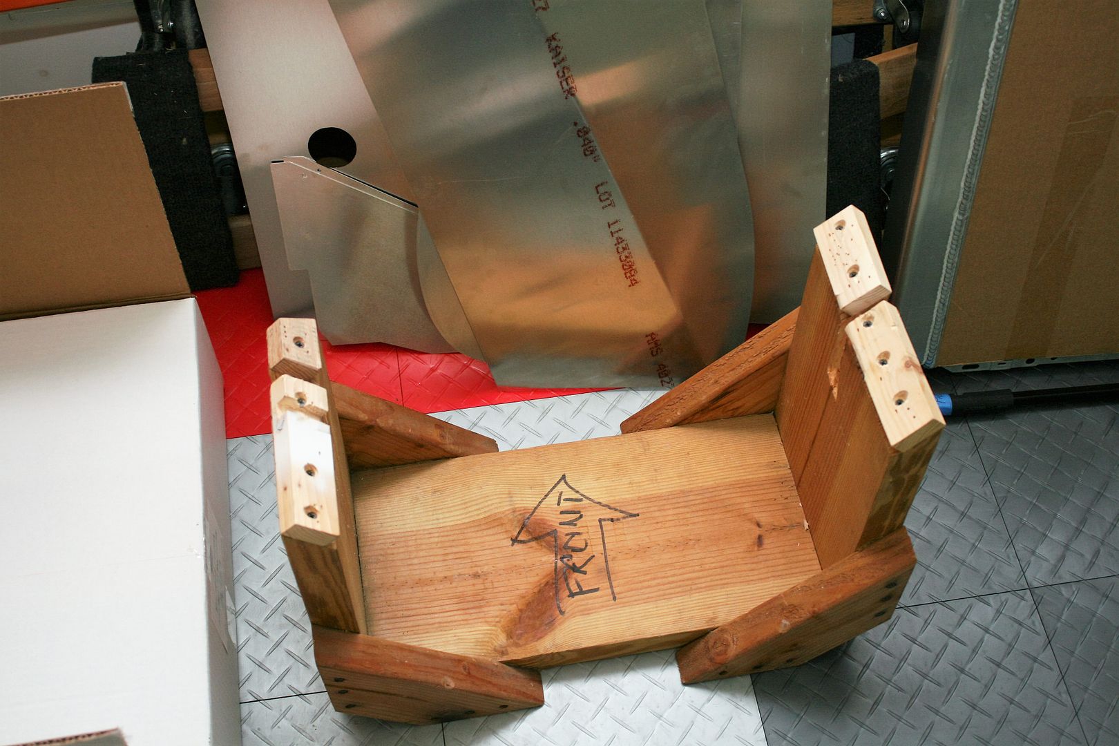
This is my super high tech engine stand. Just dimensional lumber with an angle and notches to fit the engine mounts. It's put together with lag screws and long wood screws. Has proven to be plenty strong. I built this really fast when I was in a pinch a few years ago, and it sticks around for more builds. Better than using an old tire.  Real versions of these are available at Summit and elsewhere for not too much.

Originally Posted by
russelljones48

Thanks - the other post gives me a good idea of what's needed. Looking forward to more on your build. Do you have maker and part number for the clutch switches?
The two on the left were received with the control pack. The bottom switch I will replace with the pin switch like on the right. Not sure about the top one yet. The switches from Ford are fine. Just a little clunky to mount.
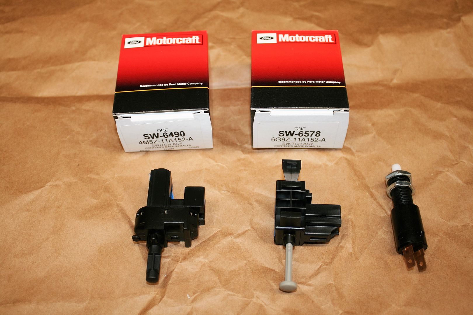
Last edited by edwardb; 10-27-2015 at 05:18 PM.
Build 1: Mk3 Roadster #5125. Sold 11/08/2014.
Build 2: Mk4 Roadster #7750. Sold 04/10/2017.
Build Thread
Build 3: Mk4 Roadster 20th Anniversary #8674. Sold 09/07/2020.
Build Thread and
Video.
Build 4: Gen 3 Type 65 Coupe #59. Gen 3 Coyote. Legal 03/04/2020.
Build Thread and
Video
Build 5: 35 Hot Rod Truck #138. LS3 and 4L65E auto. Rcvd 01/05/2021. Legal 04/20/2023.
Build Thread. Sold 11/9/2023.
-
THANKS!! Will start on that stand and those plates soon..
RJ "A race car exists in only two states: broken or in the process of becoming that way" Road and Track, May 2015
-
Carl

I am not building with a coyote but really enjoy your threads and the help they provide us all!
Mk 4 Roadster
October 25, 2012 - Kit Arrives
April 8, 2013 - Build Starts
August 23, 2015 - Rolling Chassis/Engine & Transmission Installed
March 26, 2016 - Go Cart
-
Senior Member


Originally Posted by
carlewms

I am not building with a coyote but really enjoy your threads and the help they provide us all!
Cool!  Thanks.
Build 1: Mk3 Roadster #5125. Sold 11/08/2014.
Build 2: Mk4 Roadster #7750. Sold 04/10/2017.
Build Thread
Build 3: Mk4 Roadster 20th Anniversary #8674. Sold 09/07/2020.
Build Thread and
Video.
Build 4: Gen 3 Type 65 Coupe #59. Gen 3 Coyote. Legal 03/04/2020.
Build Thread and
Video
Build 5: 35 Hot Rod Truck #138. LS3 and 4L65E auto. Rcvd 01/05/2021. Legal 04/20/2023.
Build Thread. Sold 11/9/2023.
-
What would you estimate the sizes and the angle of the bend are. I have a local shop that can cut and bed. Looks like 4X5 for the flat piece and 4X7 for the bent piece and the bend about 15 degrees - bend point at 3"?
RJ "A race car exists in only two states: broken or in the process of becoming that way" Road and Track, May 2015
-
Senior Member


Originally Posted by
russelljones48

What would you estimate the sizes and the angle of the bend are. I have a local shop that can cut and bed. Looks like 4X5 for the flat piece and 4X7 for the bent piece and the bend about 15 degrees - bend point at 3"?
Close! Good guesses. Mine are 4 x 7-1/2 and 4 x 4-1/2 inches. 20 degree bend on the longer piece, since it sits flat on the exhaust header location and needs to clear the cam cover. Bend at 3 inches. The smaller one doesn't need to be bent. It goes into bosses on the DS front, and it clear's OK without bending. Note the bosses aren't the same height. I put a few washers in the back one so that the lifting bracket sits level.
Last edited by edwardb; 12-06-2015 at 10:05 AM.
Build 1: Mk3 Roadster #5125. Sold 11/08/2014.
Build 2: Mk4 Roadster #7750. Sold 04/10/2017.
Build Thread
Build 3: Mk4 Roadster 20th Anniversary #8674. Sold 09/07/2020.
Build Thread and
Video.
Build 4: Gen 3 Type 65 Coupe #59. Gen 3 Coyote. Legal 03/04/2020.
Build Thread and
Video
Build 5: 35 Hot Rod Truck #138. LS3 and 4L65E auto. Rcvd 01/05/2021. Legal 04/20/2023.
Build Thread. Sold 11/9/2023.
-
Thanks. Spent yesterday creating some brackets based on your ideas from a very odd available piece of steel - it was free :-) Is there a reason you didn't use the passenger rear mounting holes for the rear bracket and went for the header holes?
RJ "A race car exists in only two states: broken or in the process of becoming that way" Road and Track, May 2015
-
Senior Member


Originally Posted by
russelljones48

Thanks. Spent yesterday creating some brackets based on your ideas from a very odd available piece of steel - it was free :-) Is there a reason you didn't use the passenger rear mounting holes for the rear bracket and went for the header holes?
I assume you mean on the back of the PS head? Yea, I saw those, and in hindsight those would work OK I think. I'm learning as I go here, and the pictures I could find beforehand all looked like they were using a side mount location, so I chose the only available holes which were the exhaust header ones. Plus I wasn't sure about clearance from the back. Now that I have the engine in, I can see there's more clearance in back than from the side. So certainly an OK choice. There's only two negatives I can think of, now that I've done a little work on this. If you ever wanted to install/remove the engine with the body on, the chain hanging down in the back location would be very close to the edge of the body. Plus having the attachment more toward the front of the engine naturally allows it to hang down in the back, which is mostly what you need. Of course basically the same thing can be accomplished with the engine hoist load leveler. But bottom line, I think either would work.
Last edited by edwardb; 10-31-2015 at 10:19 AM.
Build 1: Mk3 Roadster #5125. Sold 11/08/2014.
Build 2: Mk4 Roadster #7750. Sold 04/10/2017.
Build Thread
Build 3: Mk4 Roadster 20th Anniversary #8674. Sold 09/07/2020.
Build Thread and
Video.
Build 4: Gen 3 Type 65 Coupe #59. Gen 3 Coyote. Legal 03/04/2020.
Build Thread and
Video
Build 5: 35 Hot Rod Truck #138. LS3 and 4L65E auto. Rcvd 01/05/2021. Legal 04/20/2023.
Build Thread. Sold 11/9/2023.
-
RJ "A race car exists in only two states: broken or in the process of becoming that way" Road and Track, May 2015
-
Senior Member

2015 Coyote Control Pack Installation
Since the last update, I’ve mainly been focused on installing the 2015 Coyote control pack. There is a lot of information on the forums, and from FF, on how to install the previous version of the Coyote control pack in the Roadster. But none that I’m aware of for the new 2015-2016 version. As I mentioned before, there are some pretty significant differences.
First thing I went after was mounting the PCM. The large cable off the front PS corner of the engine goes to the PCM, and the length and position of that cable just about dictates only one location as I showed previously. I played around with several patterns (cereal boxes to the rescue again) and ended up with this version and cut/bent some aluminum. It will rivet to the underside of the top 3/4 inch tube and the outside of the lower 3/4 inch tube. I used some 1/2 inch shock mounts to locate the PCM on the outside of the new bracket. The shock mounts don’t have much give for the light weight of the PCM. But between the mounts and the .040 aluminum, it has just a little give but still very solid. It’s as far away from the header as I could place it, with the bracket shielding facing the header and an airspace between. The heat sinks for the PCM are facing the other way and completely open. This area should have decent airflow with the side vent right behind it. So I’m satisfied the PCM shouldn't see any extreme temps and is reasonably protected. I'll have the new piece powder coated when I do everything else, and then rivet it permanently.
I started routing some of the cables. It’s still a work in process, so no style points. Lots of straightening and clean-up to do yet. It’s not going to be very pretty no matter what, but mostly will be hidden inside the fender. The control pack harness goes into the other large connector in the PCM, with a large branch going from there to the power distribution box. That I’m going to mount on the firewall, low and just about on center. More about that later. The branches for the MAF sensor and alternator control wires go up and around the engine under the cover, so good there. I’ll need to add extensions to the fan and starter trigger wire to reach their intended destinations. The rest of the connections are on the other side of the firewall. Once you get your head around it, the connections to the Coyote are pretty simple. Here are a couple pics of where I’m at with this part.
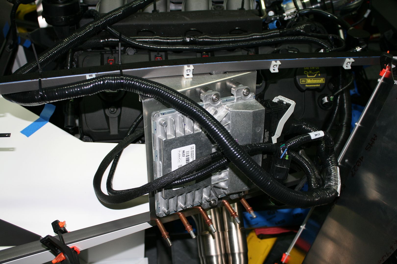
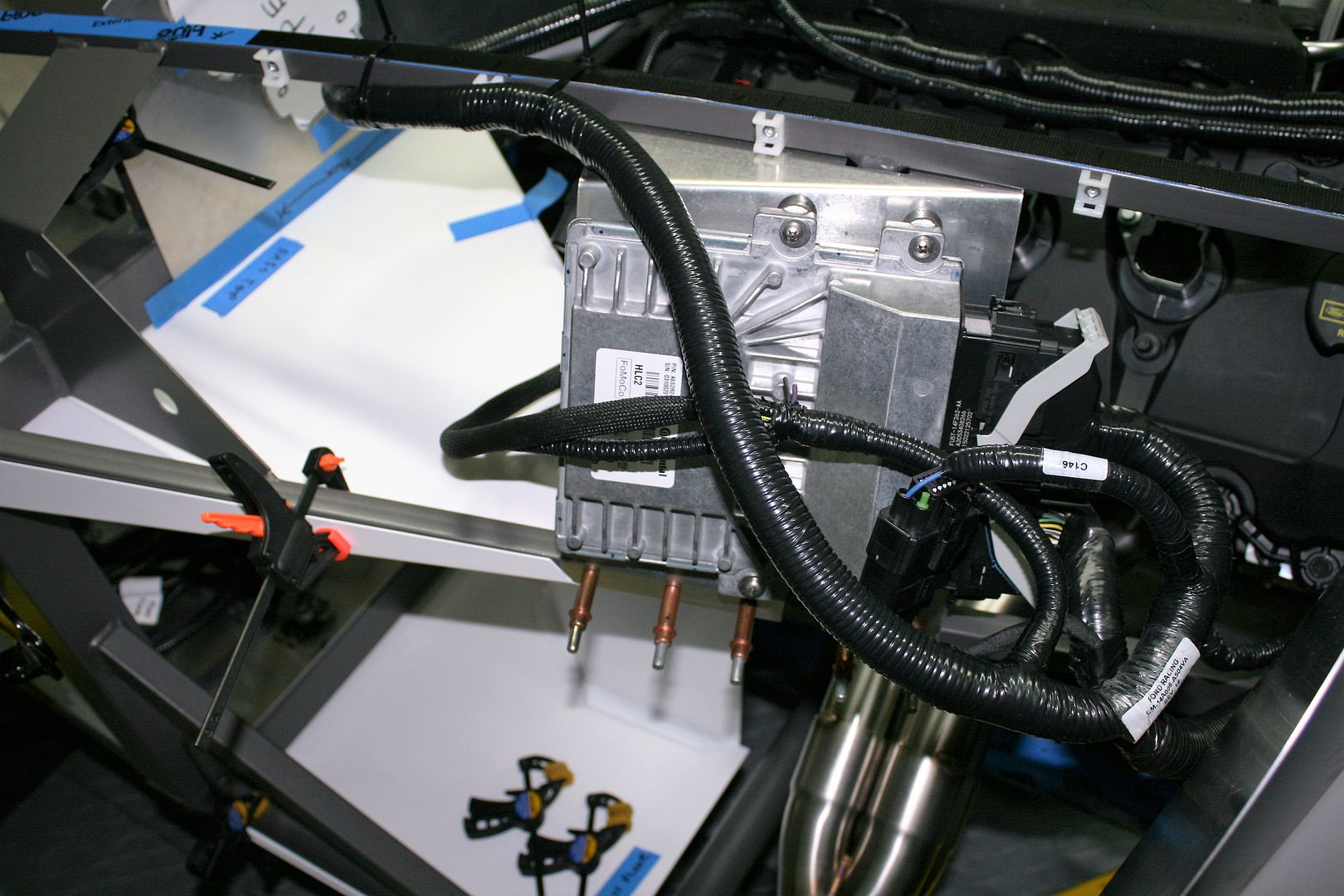
I posted a picture before of the power distribution module. This is part of some of the differences between this control pack and the previous one. Here it is with the covers off. You can see two power connections. The large lug on the front and then a power cable that exits the harness just a few inches away from the box. Today I checked every fuse and relay in the box. Most are connected to the large lug in the front, and only a couple to the separate power cable.
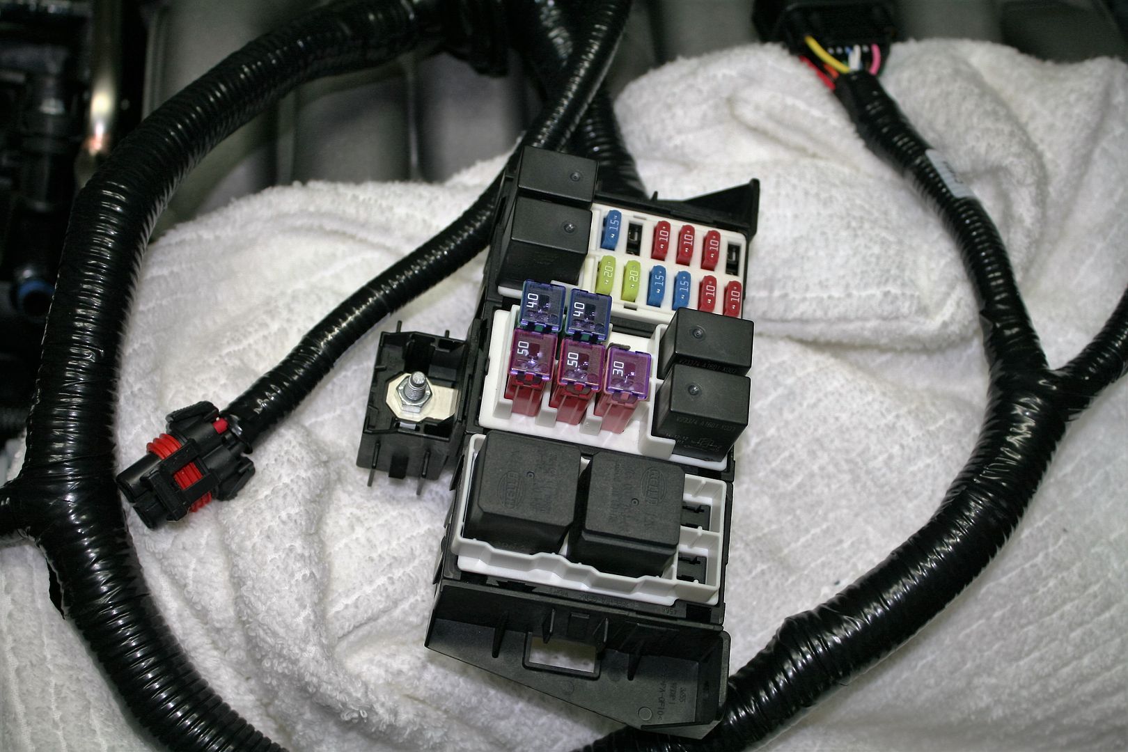
The control pack includes a massive 15 foot long power cable. Nothing like this is included in the previous control pack versions. The instructions describe connecting the power cable directly to the battery, and also includes a 250 amp fuse to be placed at the battery end. Also included are lugs and shrink sleeve to shorten the cable if necessary.
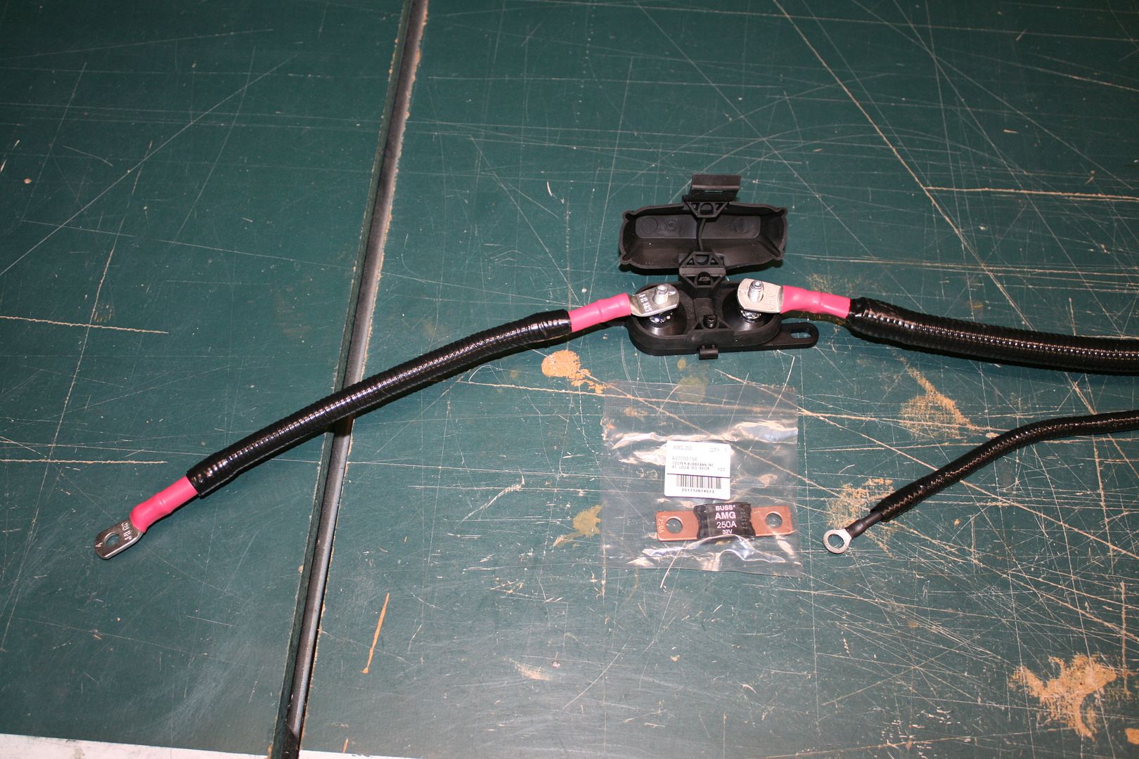
Then it’s routed to the power distribution box with a lug for the large connection on the front and a connector for the separate cable.
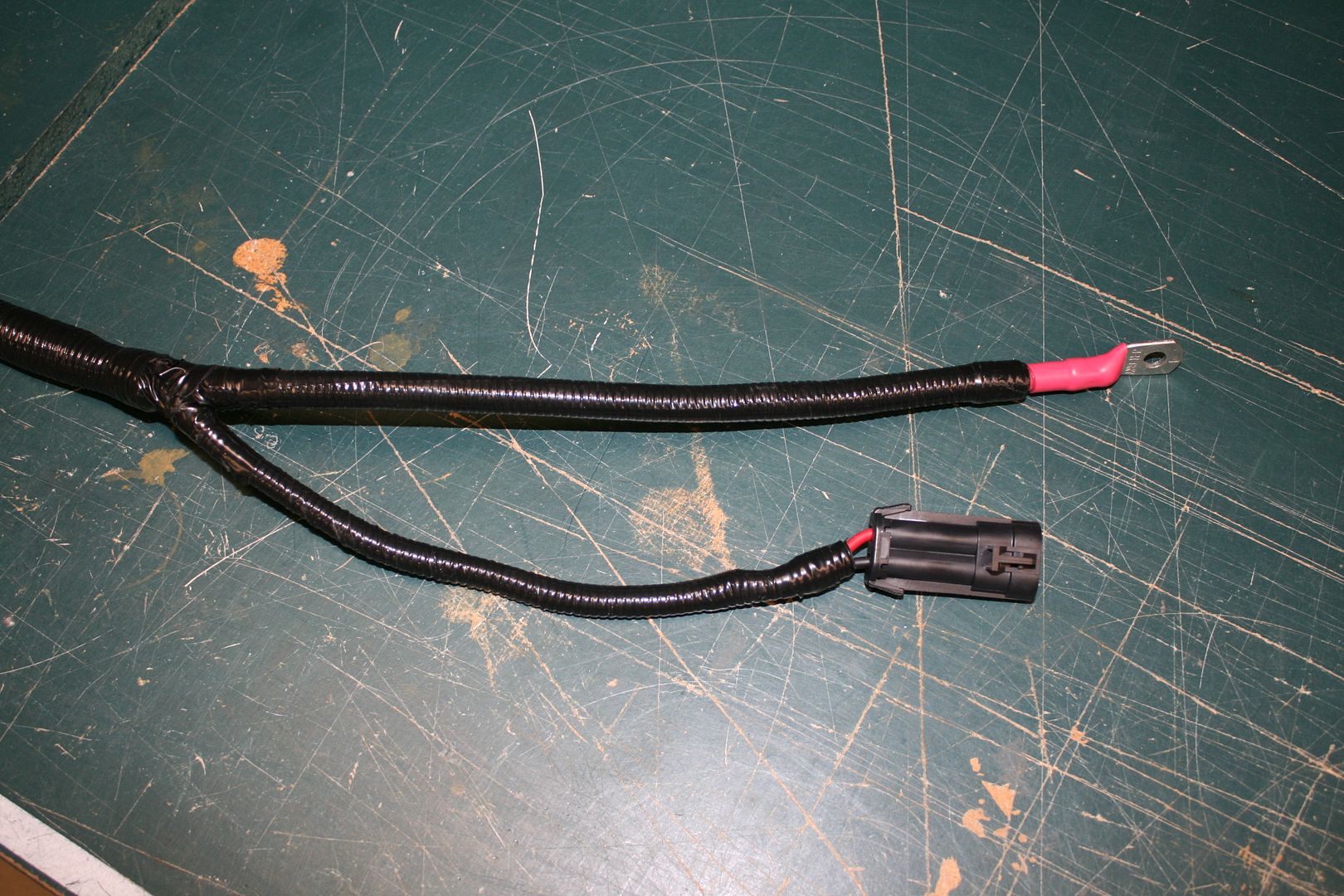
Checking continuity in the cable, the +12V connections are tied together. Now I’m not an electrical engineer (no comments please…) and I guess I understand why Ford engineers chose to provide a home run cable from the battery to the power for the control pack. This is a universal kit and will be installed in many different cars with many configurations. Getting the power directly from the battery makes it consistent for all. As for the other end, with the lug and plug, both have the same +12V power, so I guess this is related to the power distribution box adapted to this setup.
But I’m thinking now not to install it with the provided battery power cable. Like my previous build, I’m planning a master power disconnect centered under the dash with the lugs extending into the engine compartment. Whether I do a front or rear battery (still considering…) the first stop for uninterrupted battery power will be inches away from the power distribution box at the center of the firewall. Assuming I use the right size cable, I see no reason to run a duplicate battery cable.
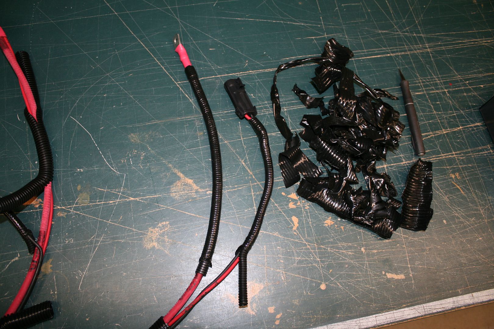
Just to confirm how the provided power cable is wired, and to prove this plan, I stripped the insulation off each end of the provided cable. The continuity checker didn’t lie. This is the power distribution box end. Large 4 gauge +12V wire to the lug, and smaller gauge power and ground.
This is the battery end, showing the two +12V wires tied together at the battery lug and the separate ground wire.
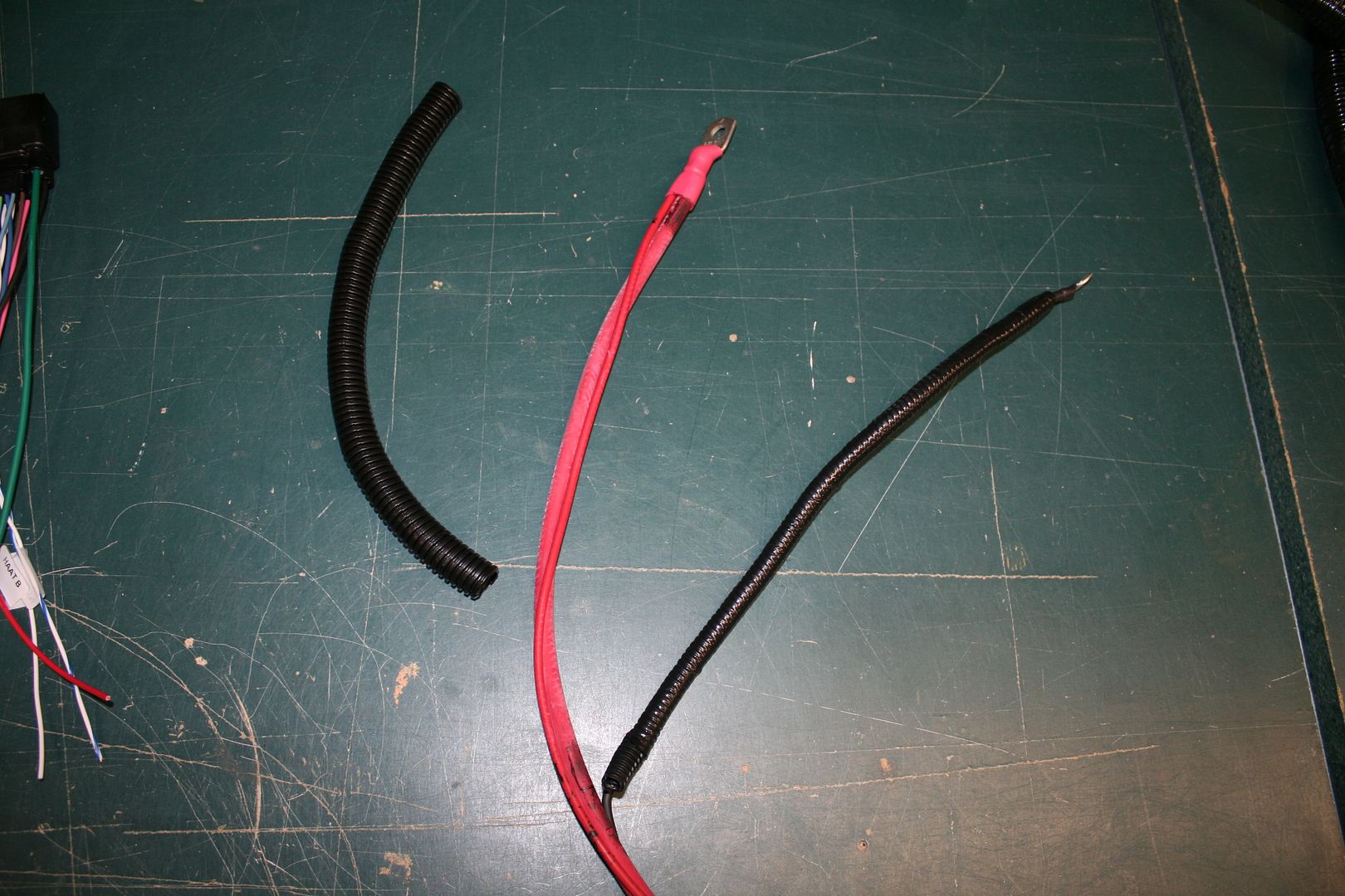
So the power setup I’m considering is +12V battery power to the master disconnect. Off the same lug, I’ll tap to the two control pack power distribution +12V connections through the provided 250 amp fuse. So they’ll have always on fused power. Just like the provided cable. On the switched side of the master disconnect, I’ll go to the RF fuse box. So technically, not everything will be switched off with the master disconnect. But the PCM has to have always on power to store settings and codes, and there’s no provision to do this other than to leave it connected through the main power leads. Based on how the RF harness is connected to the control pack using the ignition sense wires, the main disconnect will still shut down the car when switched off. I would ground the battery to the chassis, per normal. The control pack has several ground connections, also I would take to chassis. Done properly, I don’t see why I need the dedicated ground wire in the provided power cable.
If anyone has any feedback about any of this, fire away.
Last edited by edwardb; 10-31-2015 at 07:43 PM.
Build 1: Mk3 Roadster #5125. Sold 11/08/2014.
Build 2: Mk4 Roadster #7750. Sold 04/10/2017.
Build Thread
Build 3: Mk4 Roadster 20th Anniversary #8674. Sold 09/07/2020.
Build Thread and
Video.
Build 4: Gen 3 Type 65 Coupe #59. Gen 3 Coyote. Legal 03/04/2020.
Build Thread and
Video
Build 5: 35 Hot Rod Truck #138. LS3 and 4L65E auto. Rcvd 01/05/2021. Legal 04/20/2023.
Build Thread. Sold 11/9/2023.
-
Senior Member

This Week's Update
A little less time for building since my last update, but still some progress to share. I think I’m getting close on figuring out where to put the 2015 Coyote wiring. After a lot of experimentation, finalized the firewall location for the power distribution box. I did decide to go ahead and make up a .090 thick firewall. Really no big reason since I won’t be hanging anything heavy on it. Just prefer it. Since I have the 2bking modified DS footbox, the firewall has a smaller cutout than the stock one. But it was easy to make, and proceeded to drill and cleco the bottom row of rivets. With the firewall location finalized, I tapped some 1/4 x 20 threads into the firewall and 2 inch dash tube for the power distribution box mounting. Then cut the 2 inch hole for the control pack wiring to go into the dash area. I’m satisfied with how this turned out. Visible wiring will be pretty minimal.
This is the finalized location for the power distribution box. Pretty accessible from the driver’s side, and low enough that even with the body overhang should be able to get to it OK. Also shows where the cable goes through the firewall. All my power wiring will be directly below this area at the master disconnect, so an easy hook-up to the box.
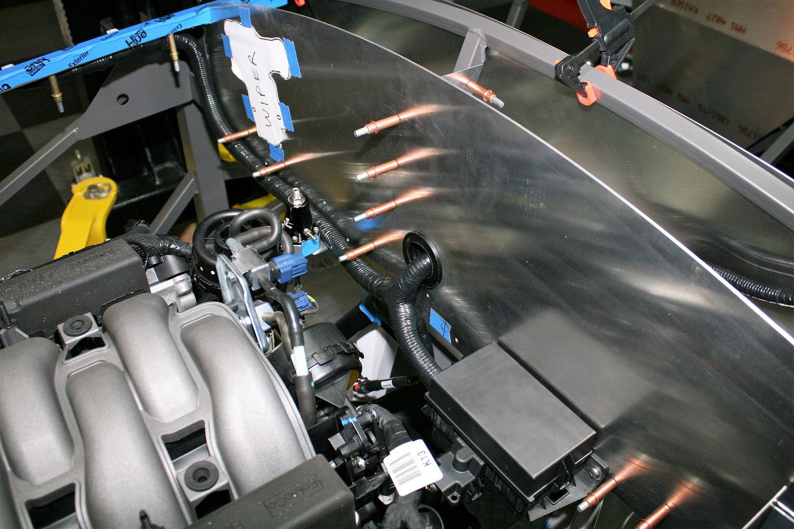
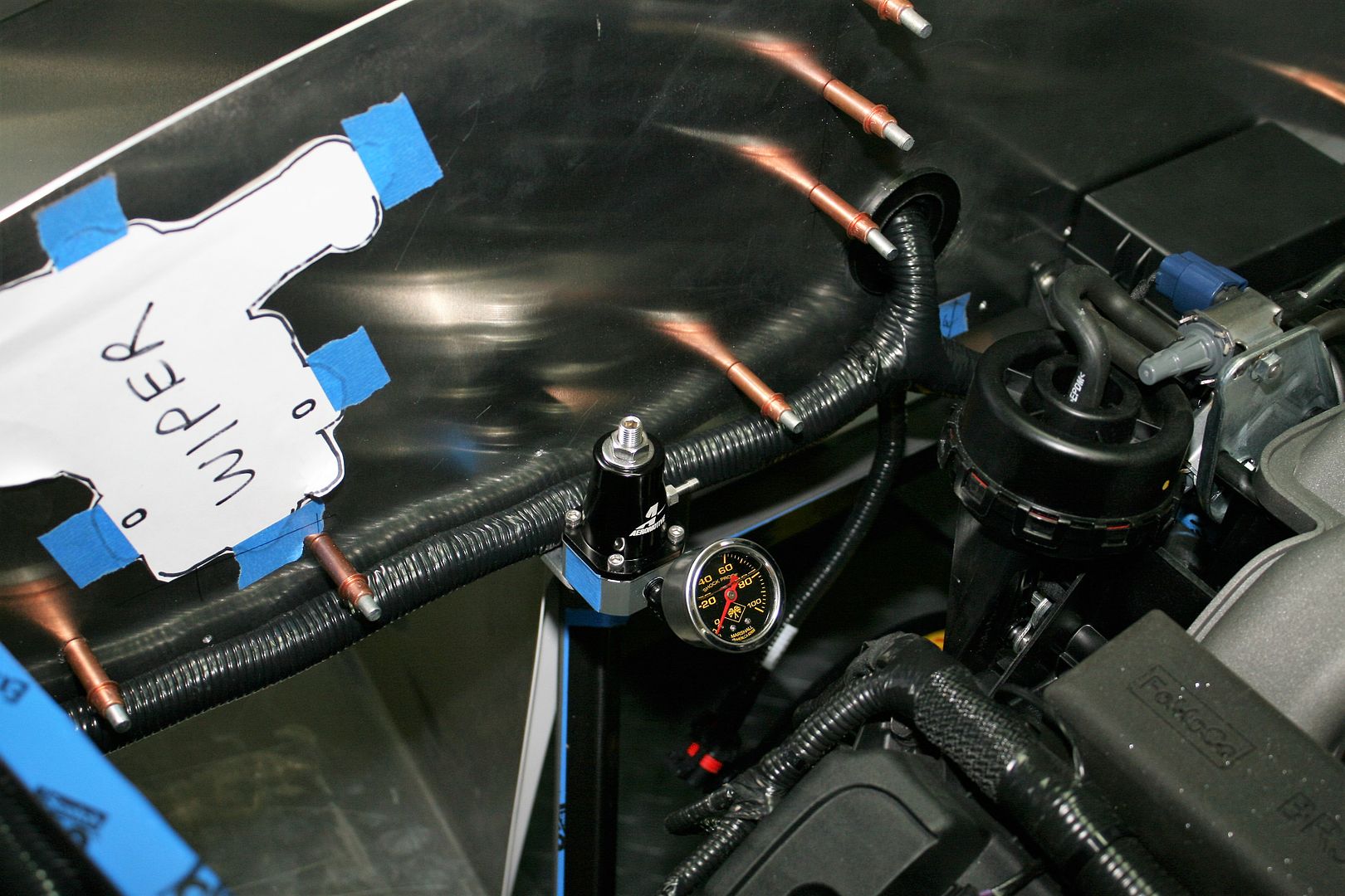
The cable runs along the bottom of the firewall. I’ll straighten and tie this down once all the sheet metal is in. Note also the very general location of the fuel regulator. It will be several inches over toward the center from what's pictured here. I made a new mounting bracket for the regulator that's straight vs. the right angle one that came with it. That will allow me to mount it on the bottom of the 2 inch tube and stand away enough to clear the control cable behind. Should work OK.
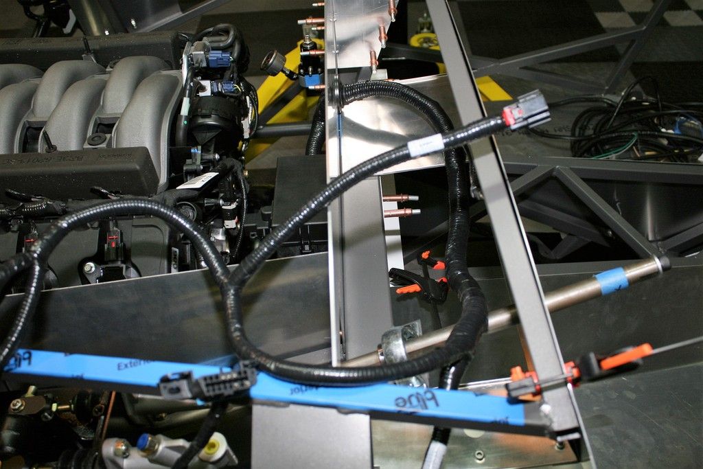
This is a pretty crummy picture, but shows the control pack wiring on the other side of the firewall. The lengths are all going to work out pretty well. That’s the DBW connector sticking up above the dash. The length is about perfect to go down to the pedal. The clutch up and down switch cable lengths are also about right. The ODB2 cable is way too long, but easy enough to shorten.
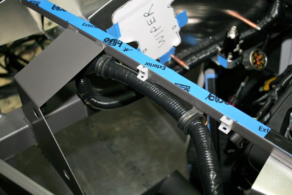
Here’s how I ended up anchoring the cable out of the PCM to the power distribution box. Two padded clamps into the underside of the 3/4 inch hood tube. The clips above are for the wire bundle from the dash to the front for the running lights in the oil cooler opening. I have similar clips on the other side for the standard RF front harness.
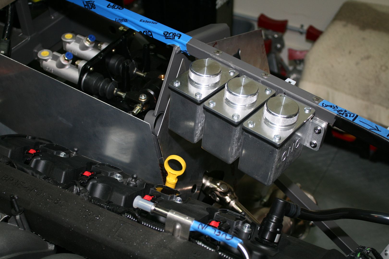
Did a couple other things. Mounted the CNC brake and clutch reservoirs. Made up another bracket to mount it from the underside of the tube. It’s tight in this area, but the location clears everything. May look a little high to some, but I carefully measured (several times) the available space in the finished Mk4, and the caps clear the hood by about 1/4 inch. Tight, but should be OK.
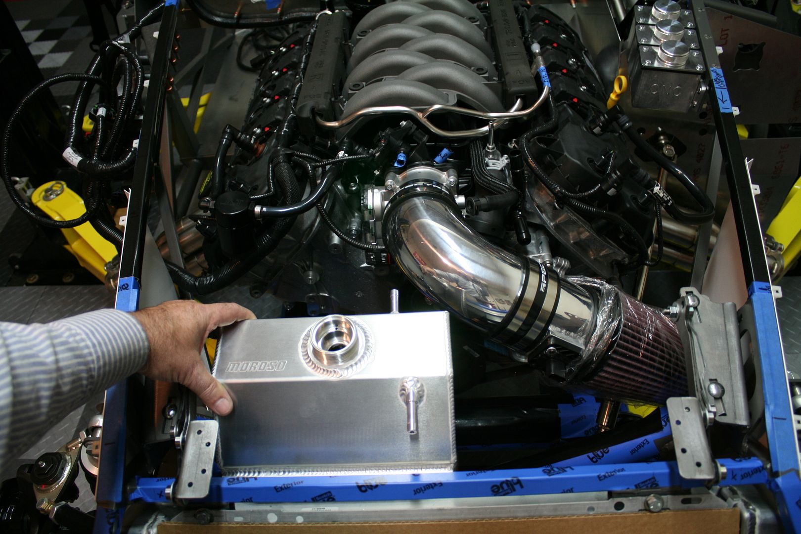
I’ve also been working on getting the radiator hooked up. Lots of great forum info on this subject for the Coyote. Like some others, I’m going to plumb it the same way Ford does in the Mustang. FF shows using a T-filler in the upper hose and a simple overflow tank. Instead I’m using an expansion tank with the filler on the tank, and then the stock hookups to the engine. I’ve got the hoses on order, and will list them once I confirm it all works and fits. The 2015 layout is slightly different and uses different parts than the previous version. In the meantime, I did receive the Moroso 63806 2015 Mustang expansion tank. Looks like it’s going to fit. I’ll need to make some brackets, but will wait until I have the hoses on hand and make everything fit together. Here I’m holding it in roughly the position I’m expecting.
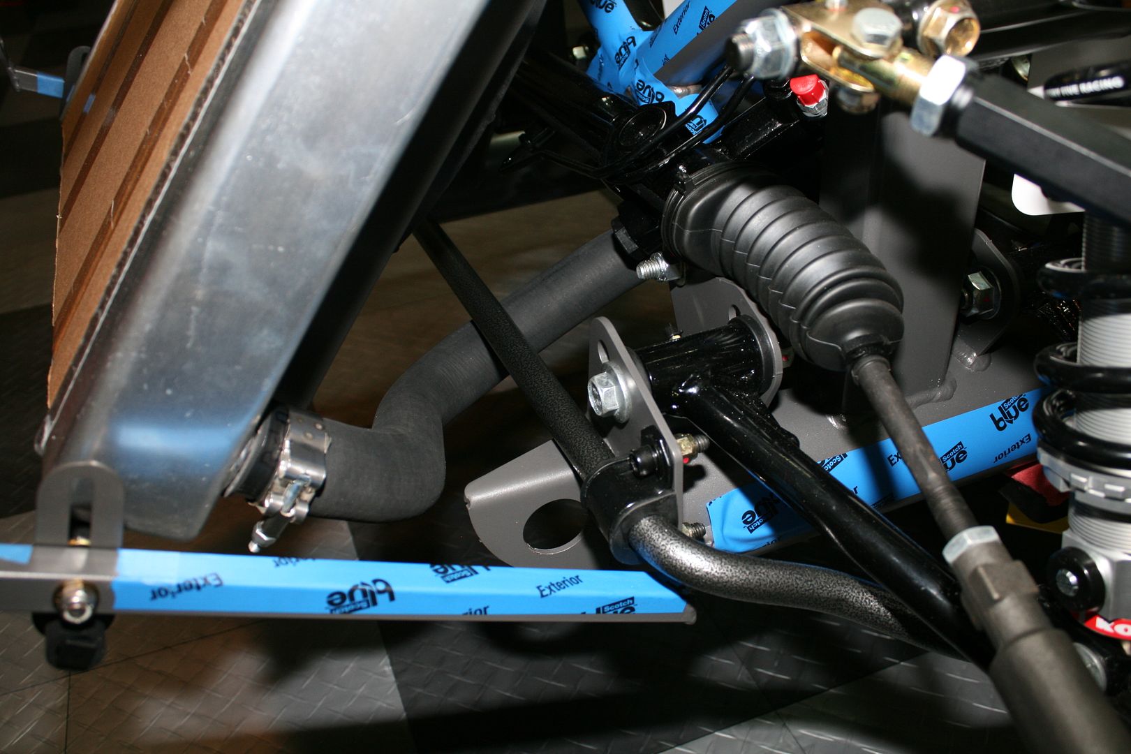
Finally, and this is a small thing, I worked on the lower radiator hose. Again the forums were a huge help showing using two pieces of a Dayco 71713 hose, a piece of mandrel bent SS tubing, and a Breeze 70612 SS hose mount. Should have the SS tubing tomorrow and I can finish this up. But just wanted to say the Dayco hose appears to be perfect. I was able to clear the front tow hook (always a challenge) and now the new challenge of the sway bar that cuts through the same area. After a little trimming and the proper orientation, looks promising. The open end will get pulled down into place when the rest of the parts are installed.
Last edited by edwardb; 11-10-2015 at 09:13 PM.
Build 1: Mk3 Roadster #5125. Sold 11/08/2014.
Build 2: Mk4 Roadster #7750. Sold 04/10/2017.
Build Thread
Build 3: Mk4 Roadster 20th Anniversary #8674. Sold 09/07/2020.
Build Thread and
Video.
Build 4: Gen 3 Type 65 Coupe #59. Gen 3 Coyote. Legal 03/04/2020.
Build Thread and
Video
Build 5: 35 Hot Rod Truck #138. LS3 and 4L65E auto. Rcvd 01/05/2021. Legal 04/20/2023.
Build Thread. Sold 11/9/2023.
-
Member

Nice work Paul. Where did you get the nifty white clips for your front wiring runs?
-
Senior Member


Originally Posted by
BobCarter

Nice work Paul. Where did you get the nifty white clips for your front wiring runs?
You're not the first to ask me about those. They are Avery Dennison #10045 Cable Tie Mounts. I got them from McMaster, their part number 7566K13. Comes in a bag of 100, so you'll have plenty for the next build.  I anchor them with 3/16 inch aluminum rivets. The hole in the mount needs to be drilled out just slightly. Depending on the specific 3/16 rivet, some will drop down into the countersink. Others need to be adjusted. If so, I put them in the drill press, and with it turning a couple swipes with a file and they fit perfectly. I usually make up 10-20 at a time, and just have them available. Makes a really clean and strong installation.
Last edited by edwardb; 11-11-2015 at 07:06 AM.
Build 1: Mk3 Roadster #5125. Sold 11/08/2014.
Build 2: Mk4 Roadster #7750. Sold 04/10/2017.
Build Thread
Build 3: Mk4 Roadster 20th Anniversary #8674. Sold 09/07/2020.
Build Thread and
Video.
Build 4: Gen 3 Type 65 Coupe #59. Gen 3 Coyote. Legal 03/04/2020.
Build Thread and
Video
Build 5: 35 Hot Rod Truck #138. LS3 and 4L65E auto. Rcvd 01/05/2021. Legal 04/20/2023.
Build Thread. Sold 11/9/2023.
-
Member


Originally Posted by
edwardb

You're not the first to ask me about those. They are Avery Dennison #10045 Cable Tie Mounts. I got them from McMaster, their part number 7566K13. Comes in a bag of 100, so you'll have plenty for the next build.

I anchor them with 3/16 inch aluminum rivets. The hole in the mount needs to be drilled out just slightly. Depending on the specific 3/16 rivet, some will drop down into the countersink. Others need to be adjusted. If so, I put them in the drill press, and with it turning a couple swipes with a file and they fit perfectly. I usually make up 10-20 at a time, and just have them available. Makes a really clean and strong installation.
Thanks for the tip on the cable tie clamps!
-
11-11-2015, 10:15 AM
#100
I continue to be thankful for your thorough documentation. Can you tell me where you purchased the CNC Brake and Clutch reservoirs?
-
11-11-2015, 10:38 AM
#101
Senior Member


Originally Posted by
Jazzman

I continue to be thankful for your thorough documentation. Can you tell me where you purchased the CNC Brake and Clutch reservoirs?
Thanks! The CNC 1483 Triple Master Aluminum Remote Resevoir is from Car Shop Inc. Other places sell them, but this was the best price at the time. If you install one, take a look also at the CNC 1459A pressure bleeder lid that works with this. The easiest way to do bleeding I've found yet.
Last edited by edwardb; 11-13-2015 at 07:28 AM.
Build 1: Mk3 Roadster #5125. Sold 11/08/2014.
Build 2: Mk4 Roadster #7750. Sold 04/10/2017.
Build Thread
Build 3: Mk4 Roadster 20th Anniversary #8674. Sold 09/07/2020.
Build Thread and
Video.
Build 4: Gen 3 Type 65 Coupe #59. Gen 3 Coyote. Legal 03/04/2020.
Build Thread and
Video
Build 5: 35 Hot Rod Truck #138. LS3 and 4L65E auto. Rcvd 01/05/2021. Legal 04/20/2023.
Build Thread. Sold 11/9/2023.
-
11-12-2015, 08:37 AM
#102
Argh. I had the CNC 1483 on order from another site and just received an email/refund stating they are out of stock. I went to check out the Car Shop (which had 2 yesterday) and now they are out of stock too. The hunt continues... - UPDATE - I just called the manufacturer and ordered the Reservoir and pressure bleeder lid directly.
Last edited by RRussellTx; 11-13-2015 at 11:31 AM.
-
11-15-2015, 08:47 AM
#103
Senior Member

Hey Edward, This is my first build, I'm #9 for the 20th anniversary cars. Wanted to say thanks for all your suggestions and detailed postings they've been extremely helpful as I move along. I'm still waiting on the brakes as well, I was told a few weeks ago they would be shipped soon. I'm planning on PC all the non white panels gray to match the frame, has anyone come across the powder coat paint codes for the chassis so I can match the panels exactly? Thanks again
-
11-15-2015, 09:09 AM
#104
Senior Member


Originally Posted by
Paul_M

Hey Edward, This is my first build, I'm #9 for the 20th anniversary cars. Wanted to say thanks for all your suggestions and detailed postings they've been extremely helpful as I move along. I'm still waiting on the brakes as well, I was told a few weeks ago they would be shipped soon. I'm planning on PC all the non white panels gray to match the frame, has anyone come across the powder coat paint codes for the chassis so I can match the panels exactly? Thanks again
Congrats on your anniversary build. Glad you find my build thread helpful. Brakes are supposedly shipping now, although I haven't seen anything. Seems we're getting very close though. Factory Five tech support posted the anniversary powder coat colors in another thread. They are: Prismatic Powders PSS-1353 soft satin white and Tiger Drylac DB 703 Glimmer, 49/84340. I'm planning to match all the unfinished panels as well. Keep us posted with your build!
Build 1: Mk3 Roadster #5125. Sold 11/08/2014.
Build 2: Mk4 Roadster #7750. Sold 04/10/2017.
Build Thread
Build 3: Mk4 Roadster 20th Anniversary #8674. Sold 09/07/2020.
Build Thread and
Video.
Build 4: Gen 3 Type 65 Coupe #59. Gen 3 Coyote. Legal 03/04/2020.
Build Thread and
Video
Build 5: 35 Hot Rod Truck #138. LS3 and 4L65E auto. Rcvd 01/05/2021. Legal 04/20/2023.
Build Thread. Sold 11/9/2023.
-
11-15-2015, 10:52 AM
#105
Senior Member

Excellent, thanks. Today will be working the IRS. Here's a photos as she sits....CheersIMG_3264.JPG
-
11-17-2015, 11:12 AM
#106
Edwardb, Thanks for your hospitality in letting me stop by on the way home from the build school. The insight into the build and actually viewing your build was excellent. I think I will be ready to receive my anniversary kit in a few weeks and start a build site. Not anywhere close to yours but hopefully great. I did get to stop by Roush and took the plant tour. Amazing. The automotive engine building supports a huge Merlin aviation engine build site which Jack Roush has had a passion for. I'm swaying toward that 351 they have. A person does have to pay for their engine at a premium but it is an anniversary build and it will add value to this one. Jim
Last edited by RR20AC; 11-19-2015 at 01:24 AM.
-
11-17-2015, 01:58 PM
#107
Senior Member


Originally Posted by
RR20AC

Edwardb, Thanks for your hospitality in letting me stop by on the way home from the build school. The insight into the build and actually viewing your build was excellent. I think I will be ready to receive my anniversary kit in a few weeks and start a build site. Not anywhere close to yours but hopefully great. I did get to stop by Roush and took the plant tour. Amazing. The automotive engine building supports a huge Merlin aviation engine build site which Jack Roush has had a passion for. I'm swaying toward that 351 they have. A person does have to pay for their engine at a premium but it is and anniversary build and it will add value to this one. Jim
Hey Jim! It was my pleasure. It was great to meet you and happy you had the time to stop by. It's fun sharing the build, and glad it was helpful for you. Also great you had time for the visit to Roush. That would be awesome if you decide to go that way. Good luck with your upcoming delivery. May your backorder list be short and your build time enjoyable. 
Build 1: Mk3 Roadster #5125. Sold 11/08/2014.
Build 2: Mk4 Roadster #7750. Sold 04/10/2017.
Build Thread
Build 3: Mk4 Roadster 20th Anniversary #8674. Sold 09/07/2020.
Build Thread and
Video.
Build 4: Gen 3 Type 65 Coupe #59. Gen 3 Coyote. Legal 03/04/2020.
Build Thread and
Video
Build 5: 35 Hot Rod Truck #138. LS3 and 4L65E auto. Rcvd 01/05/2021. Legal 04/20/2023.
Build Thread. Sold 11/9/2023.
-
11-17-2015, 07:56 PM
#108
Paul_M
Looks awesome. We never get tired of seeing new arrivals.
-
Post Thanks / Like - 1 Thanks, 0 Likes
 D02G
D02G thanked for this post
-
11-21-2015, 07:17 AM
#109
Senior Member

Hey Edward, as mentioned my plan is to powder coat all the stainless panels gray to match the frame, I think you are doing the same. You are much further along in the build than I am, and just wanted to ask are you doing all the stainless panels gray or did you find that you are doing some satin white to better match the white ones that came white with our kit? Also has anyone received their brakes? I'm still waiting on these and the CV axels? Thanks
-
11-21-2015, 07:51 AM
#110
Senior Member


Originally Posted by
Paul_M

Hey Edward, as mentioned my plan is to powder coat all the stainless panels gray to match the frame, I think you are doing the same. You are much further along in the build than I am, and just wanted to ask are you doing all the stainless panels gray or did you find that you are doing some satin white to better match the white ones that came white with our kit? Also has anyone received their brakes? I'm still waiting on these and the CV axels? Thanks
I assume you mean aluminum panels. Unless you received an upgrade none of the rest of us did.  Yes, I'm going to have all the panels powder coated. The only white ones will be the ones in/around the engine compartment, as already provided by FF. Because I've got some modded panels for the Coyote, I'll need to get them coated white to match. But the balance will be the same color as the chassis. The idea of the white panels is to simulate the look of the originals that had white fiberglass footboxes. Do it however you want though. As we often say around here, it's your build. Do it how you want. I did receive my CV axles some weeks ago, but I know they still have a number backordered. They're from The Driveshaft Shop in NC, and appear to be quality pieces. Not sure why they're taking so long though. The special Wilwood brakes are just starting to ship. I received a tracking number yesterday for the front set. I don't have a promise yet for the back set. They supposedly ship the backordered parts in the order of kit deliveries.
Build 1: Mk3 Roadster #5125. Sold 11/08/2014.
Build 2: Mk4 Roadster #7750. Sold 04/10/2017.
Build Thread
Build 3: Mk4 Roadster 20th Anniversary #8674. Sold 09/07/2020.
Build Thread and
Video.
Build 4: Gen 3 Type 65 Coupe #59. Gen 3 Coyote. Legal 03/04/2020.
Build Thread and
Video
Build 5: 35 Hot Rod Truck #138. LS3 and 4L65E auto. Rcvd 01/05/2021. Legal 04/20/2023.
Build Thread. Sold 11/9/2023.
-
11-21-2015, 10:16 AM
#111
Senior Member

Thanks Edward. Yep no special upgrade here, just the aluminum panels...the non finished steel parts I'm thinking gloss black except for the quick jacks which I'm going to chrome. I'll follow up with FF on Monday to check on my brakes and axles. Thanks
-
11-23-2015, 09:02 PM
#112
Senior Member

IRS Question
Hey Edward, quick question for you. Installed my rear center section tonight, all 4 bolts in and when I look from the front down the middle of the car the driveshaft isn't dead center. It sits to the left, almost looks like there will be some interference with a frame bracket. Did you have any issues on your end, do you know if you're is dead center. Given how tight it is to get the diff in and the 4 bolts I can't see how it can be off.
IMG_3358.JPGIMG_3359.JPG
-
11-23-2015, 09:28 PM
#113
Senior Member


Originally Posted by
Paul_M

Hey Edward, quick question for you. Installed my rear center section tonight, all 4 bolts in and when I look from the front down the middle of the car the driveshaft isn't dead center. It sits to the left, almost looks like there will be some interference with a frame bracket. Did you have any issues on your end, do you know if you're is dead center. Given how tight it is to get the diff in and the 4 bolts I can't see how it can be off.
You're fine. The whole drivetrain -- engine, trans, driveshaft, and center section (diff) -- are slightly off-center toward the passenger side. As I recall the amount is in the 1-2 inches range, but I'm not positive about that. You'll find out, if you haven't already, that the exhaust manifolds are different lengths. Again, because everything is slightly toward the passenger side. I've heard it's done for balance purposes because only one person in the driver's seat is the most common. Also have heard it's for space purposes, e.g. foot space, pedals, steering column, etc. on the driver's side. Whatever the reason, most DD's of every brand are the same way.
I wouldn't worry about frame clearance. I agree it looks tight. But I think there's enough room. Plus with IRS, the center section doesn't move. So the clearance you see is what you'll always have.
Build 1: Mk3 Roadster #5125. Sold 11/08/2014.
Build 2: Mk4 Roadster #7750. Sold 04/10/2017.
Build Thread
Build 3: Mk4 Roadster 20th Anniversary #8674. Sold 09/07/2020.
Build Thread and
Video.
Build 4: Gen 3 Type 65 Coupe #59. Gen 3 Coyote. Legal 03/04/2020.
Build Thread and
Video
Build 5: 35 Hot Rod Truck #138. LS3 and 4L65E auto. Rcvd 01/05/2021. Legal 04/20/2023.
Build Thread. Sold 11/9/2023.
-
11-23-2015, 09:35 PM
#114
Senior Member

Thanks very much Edward, really appreciate the quick response and again thanks for all the detail in your posts. Has been a great help and time saver. Cheers
-
11-24-2015, 12:52 AM
#115
Member

.

Originally Posted by
edwardb

You're fine. The whole drivetrain -- engine, trans, driveshaft, and center section (diff) -- are slightly off-center toward the passenger side. As I recall the amount is in the 1-2 inches range, but I'm not positive about that. You'll find out, if you haven't already, that the exhaust manifolds are different lengths. Again, because everything is slightly toward the passenger side. I've heard it's done for balance purposes because only one person in the driver's seat is the most common. Also have heard it's for space purposes, e.g. foot space, pedals, steering column, etc. on the driver's side. Whatever the reason, most DD's of every brand are the same way.
I wouldn't worry about frame clearance. I agree it looks tight. But I think there's enough room. Plus with IRS, the center section doesn't move. So the clearance you see is what you'll always have.
What offset in the driveshaft is ok with this situation? I have installed my 351W coupled to an AOD and the misalighnment causes enough angle in the ends of the driveshaft that I am a bit nervous. Shorty headers are installed and impact the drivers footbox heavily. There is virtually no give anywhere to straighten the drive train.
-
11-24-2015, 07:23 AM
#116
Senior Member


Originally Posted by
BobCarter

What offset in the driveshaft is ok with this situation? I have installed my 351W coupled to an AOD and the misalignment causes enough angle in the ends of the driveshaft that I am a bit nervous. Shorty headers are installed and impact the drivers footbox heavily. There is virtually no give anywhere to straighten the drive train.
The question here, as I understood it, was about the entire driveline being off center, and whether this was normal and/or OK. As in a top view. It is normal, it's designed to be that way, and all the components should align front to back. It's not misalignment. There's a little bit of wiggle room in the engine mounts, so you could swing the engine/trans a bit side-to-side. But that's about it. Another aspect would be the side view. Here the driveline has about a 2 degree down angle toward the back. There are several adjustments available. The most common is to add spacers under the back of the transmission to affect the engine/trans angle and pinion angle. But it's also possible to add spacers under one or both engine mounts to adjust overall engine height or better alignment side-to-side (e.g. for headers). For a fixed axle build, it's also possible to rotate the diff. But not possible on these IRS builds. Especially the way the new Mustang center section is installed. A proper installation will still have some angles on the driveshaft, which is actually recommended as along as they don't exceed design limits. This response may or may not address your specific concerns. I personally have no experience with either AOD or shorty headers. So you may want to post those questions in a separate thread.
Build 1: Mk3 Roadster #5125. Sold 11/08/2014.
Build 2: Mk4 Roadster #7750. Sold 04/10/2017.
Build Thread
Build 3: Mk4 Roadster 20th Anniversary #8674. Sold 09/07/2020.
Build Thread and
Video.
Build 4: Gen 3 Type 65 Coupe #59. Gen 3 Coyote. Legal 03/04/2020.
Build Thread and
Video
Build 5: 35 Hot Rod Truck #138. LS3 and 4L65E auto. Rcvd 01/05/2021. Legal 04/20/2023.
Build Thread. Sold 11/9/2023.
-
11-24-2015, 11:39 AM
#117
Senior Member

Latest Update
I’ve been keeping with the build pretty steadily, but have waited until some progress to post. First a bit of old business. I have now closed the two open issues I had with Ford Racing regarding my 2015 Coyote crate engine. First was the O2 sensors they provided in the original controls pack did not mate to the connectors on the engine harness. Something about 4-pin not compatible with 5-pin and completely different shapes. I received a new pair of O2 sensors and they fit the engine harness. Details: The controls pack came with a pair of FL3Z-9G444-A sensors, and the installation manual on Ford Racing’s site still lists this part number. The new parts I received are FR3Z-9F472-E (LH) and FR3Z-9F472-C O2 (RH). I assume these will be a permanent change for future purchases, but I don’t know for sure. I will need one maybe two extensions, but that’s TBD until I get all the sheet metal installed and determine the final routing. The second issue was regarding the speed dial. This was an add to the 2011-2014 setup to solve a stalling issue. Ford Racing confirmed via Ford engineering that the speed dial is NOT required for the 2015 version. Apparently changes have been made so it’s unnecessary. I hope they’re right. I won’t be installing it. For now anyway.
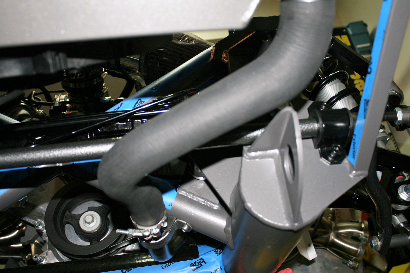
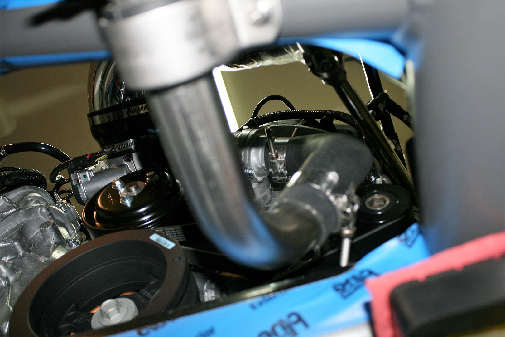
The second piece of slightly unfinished business is the lower radiator hose. Based on forum postings, I picked up a Dayco 71713 hose, a Jegs 679-MB1040 Mandrel SS 90° Bend, and a Breeze Automotive #70162 mounting bracket. The Dayco hose is split, with one end on the radiator and the other end on the engine. I showed the lower radiator connection in an earlier update. Now I have all the parts and have completed the layout. Hard to get good pics, but here’s what it looks like. I’m very happy with it. It clears the front towhook and also the sway bar. Mainly because of the sway bar, the routing is slightly different than other postings. But it still works. Those that look at these pictures in detail (and I know some of you do!) you’ll see that my T-clamps are bottomed out. I used some that I had on hand, and they were a bit too big. I have the next size down on the way, and will install those during final assembly when the engine goes back in.
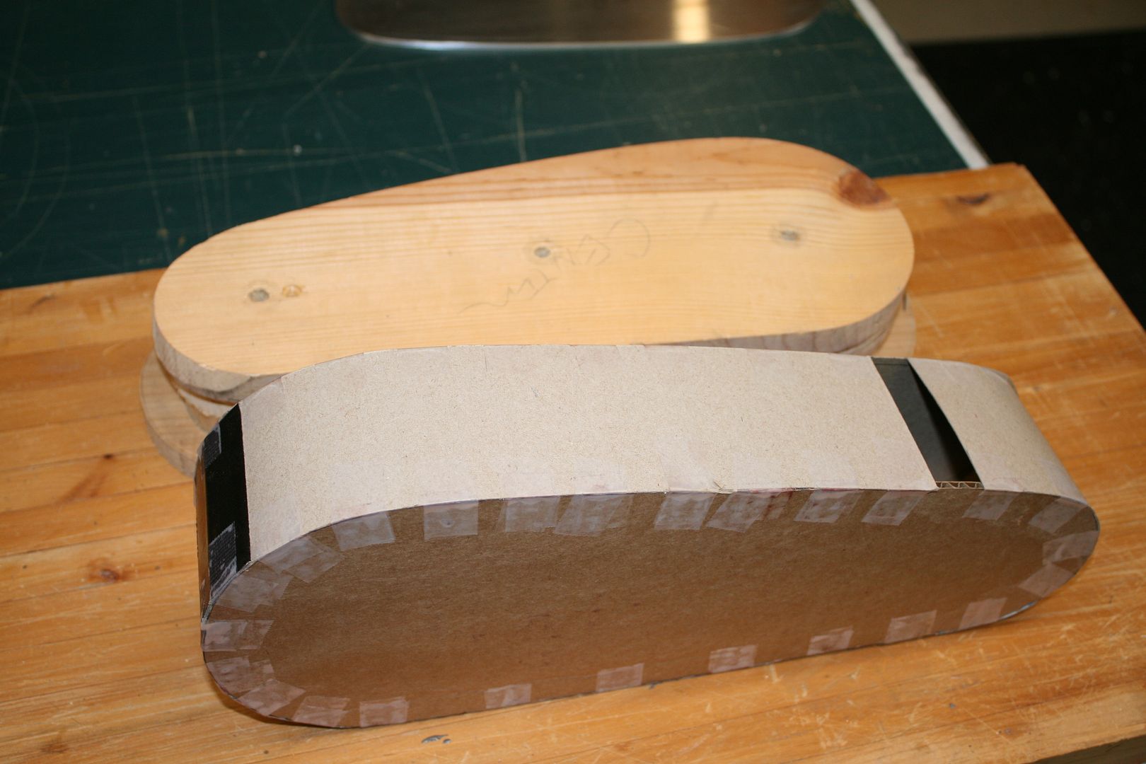
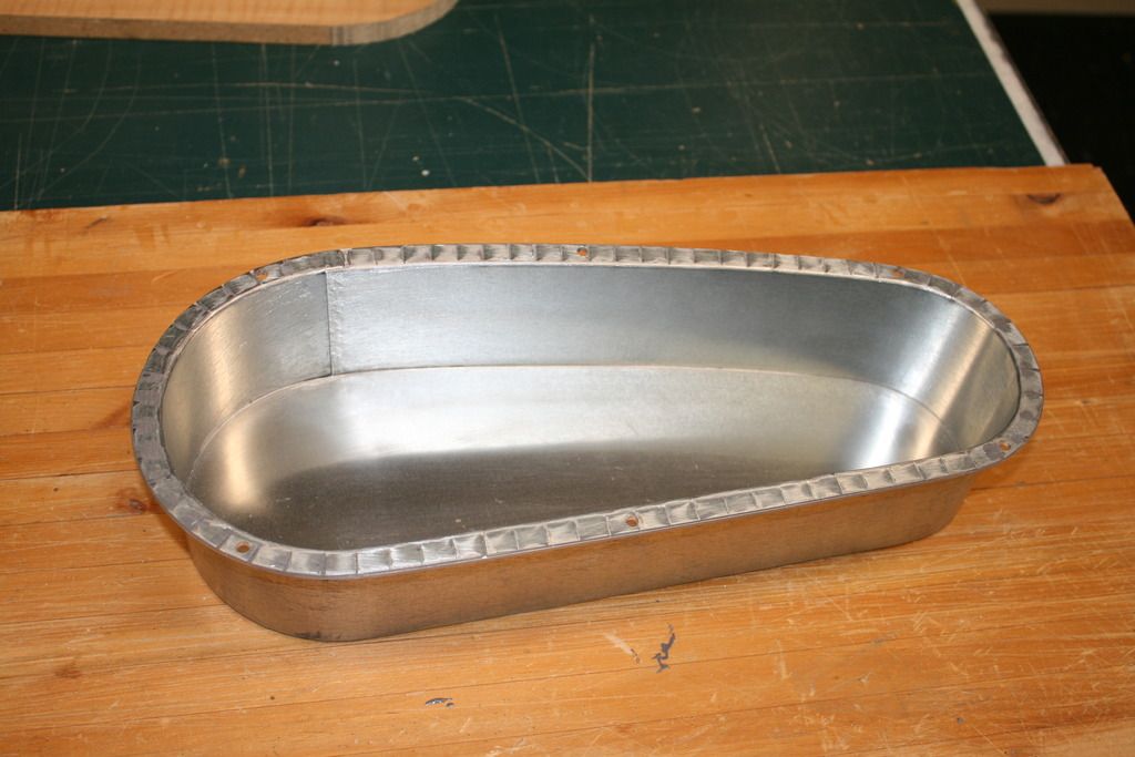
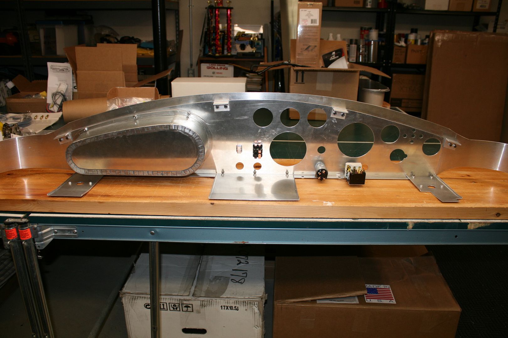
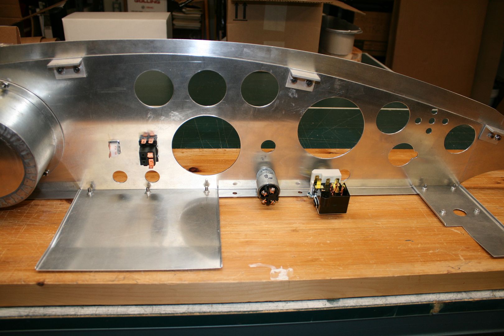
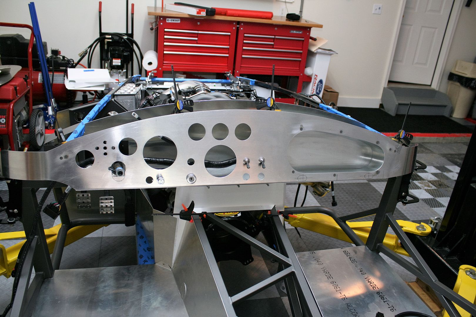
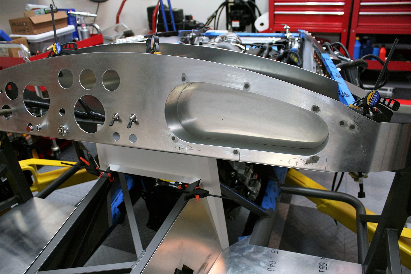
So while waiting for my Wilwood brakes, which I would prefer to have installed before starting brake and then fuel lines, and the balance of my radiator hoses which apparently are taking some special orders through Ford, I’ve been working on the instrument panel. Basically have it ready to cover. As posted earlier, I chose not to use the kit provided ready-to-use instrument panel. Mainly because it was a street layout and I prefer competition. But also I wanted to use some of my own customizations. I don’t know exactly how many hours later, but I’m still OK with that decision. But it was quite a bit of work. I started with a normal FF blank dash. I want to give leather covering a try, and I have a hide now hanging here in my basement (that’s going to be interesting…) and I want a glovebox. So I decided to make my own. It’s based on the Alex’s Custom Roadster Interior version, like I have on the other Mk4. But I revised the shape just slightly with a bit more arch along the top. For the interior, I made a mock-up out of cardboard to confirm the size and shape. Then made some patterns out of scrap wood. Bent a piece of ductwork sheet metal from HD around the form. Made a back and front ring out of aluminum, and bent it all into shape. The sheet metal ring has a folded seam along the top. The rest is held together with good old JB Weld, although once it’s bolted into place the front ring holds the box in place and the back is not going anywhere. I’ll line the interior, which shouldn’t be hard since it’s got square corners. Probably will use some of the leather (I have plenty!) but will see how that goes.
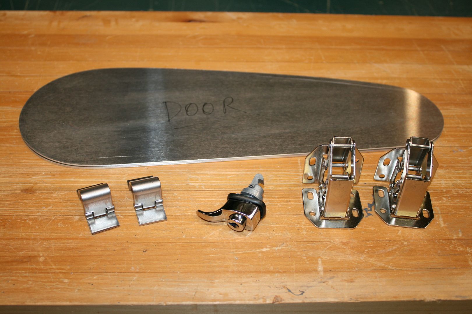
I was going to use some hinges from McMaster (LH side in the picture below) that were recommended in another forum post. I tried, but the geometry just isn’t right for me. I have to have a grab handle on my dash below the door for my wife, and the McMaster hinges dropped the door well down below the opening. Just wouldn’t have worked. After studying the hinges that Alex uses, I found the exact parts at Lowes (RH side in the picture below). So I’ll use those. The geometry works perfectly. They take a little more space inside than I would like, but so be it. I’m using a VW latch (also pictured) I bought on eBay that should be pretty slick. It latches closed and opens with a pushbutton and has a little pull tab. It can also be locked.
Last edited by edwardb; 11-24-2015 at 12:37 PM.
Build 1: Mk3 Roadster #5125. Sold 11/08/2014.
Build 2: Mk4 Roadster #7750. Sold 04/10/2017.
Build Thread
Build 3: Mk4 Roadster 20th Anniversary #8674. Sold 09/07/2020.
Build Thread and
Video.
Build 4: Gen 3 Type 65 Coupe #59. Gen 3 Coyote. Legal 03/04/2020.
Build Thread and
Video
Build 5: 35 Hot Rod Truck #138. LS3 and 4L65E auto. Rcvd 01/05/2021. Legal 04/20/2023.
Build Thread. Sold 11/9/2023.
-
11-24-2015, 11:41 AM
#118
Senior Member

Latest Update (continued)
Some, including me, like the dash to be a little more solid than the .040 aluminum used. Once it’s installed and properly braced along the bottom, the stock version is totally fine. But still some of us tinker. Some make the dash out of thicker material. I don’t have any way to make the lengthwise bend, and I’m not aware of any place to buy them. So for my last build, I just sandwiched a piece of .040 sheet on the back of the stock dash, and that actually worked out really well. So I did the same thing this time around. But some care is needed. Some of the things we normally mount in the dash (ignition switch, toggle switches, etc.) do not have enough threads for the thicker dash plus the covering. Ask me how I know that. I had to do some not too pretty after the fact mods on my last build. So this time around, put cutouts in the backer piece in the right places. I know this seems like a lot of messing around, and it probably is. Anyway, with the layout completed and the reliefs cut, I tacked the backer in place with some spots of JB Weld in all the right places. Once everything is installed (instruments, glovebox, etc.) it’s firmly held in place. The I cut out for the gauges, switches, etc. I used an adjustable circle cutter in my drill press for the larger gauge holes, and various step bits and whatever for the smaller stuff. The glovebox cutout was with a sabre saw. In most cases, I made the openings slightly larger so I can pie cut the leather and pull through and glue behind. I also added four tabs along the top which is how I like to hang the dash from the 3/4 inch dash tube. I placed them where they all have straight shots from the bottom for assembly and disassembly if required. Final results:
Two other comments. First, I looked for alternatives, but I ended up using Lucas switches for the wipers and hazards. I just haven’t found an acceptable alternative to the Lucas switch for the wipers. I’m amazed how much that’s discussed, e.g. guys not able to get them to work properly, park, etc. With that switch and wired properly, they work perfectly every time. Yea, there are some other wiring diagrams using relays, etc. But this is a case where simple is good IMO. But here’s a tip. Most of the “Lucas” switches sold in the U.S., at least that I’ve found, are not actual branded Lucas parts. Including the forum vendor that many of us use. They are knock-offs. I’ve found the genuine Lucas switches are better quality. I know that’s a relative thing when it comes to Lucas, but that’s my experience. If the switch doesn't come in a green box and have Lucas marked on the part, it's a knock-off. Additionally, the commonly used “Lucas” wiper switch doesn’t have a proper plated/polished finish on the front. The genuine Lucas switch does. Maybe it’s only me that notices stuff like that. It’s a little pricey, but I get the real Lucas stuff from Auto Electric Supplies Limited in England. They have a good website, ship quickly, and takes a week or so to cross the pond.
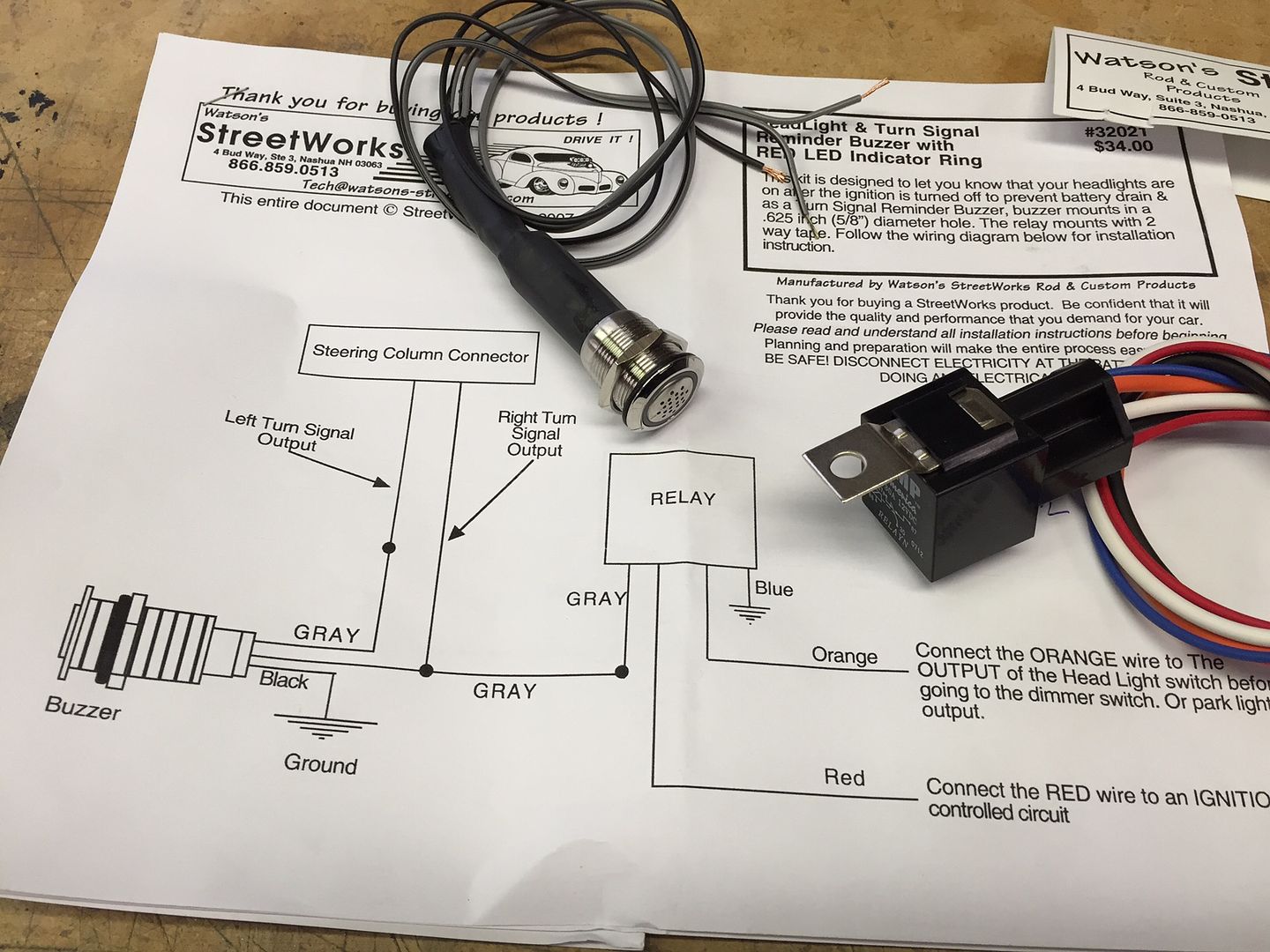
Second, I’ve added headlights on chimes (buzzers…) to my previous builds just to keep me from forgetting and leaving the lights on. Our DD’s have had automatic lights for years now, and I can just see myself forgetting. Plus these circuits don’t have a cut-off like most modern cars now. So if the lights are left on, they will stay on until the battery is dead. For my previous builds, I made my own using a Radio Shack chime and a relay. Pretty easy to do. With all our local stores closed and not wanting to really try to find another source, I noticed on Watson’s Streetworks website they had a nice light’s on reminder that even has a flashing light if you’re so inclined. Even better, I saw that it has an option to also hook to your turn signals so that you get an audible signal when the turn signals are flashing. I don’t know about you, but I can’t hear the flasher clicking in my car, and even with the dash indicator light, I occasionally discover the turn signals still flashing long after I’ve made a turn. I hate being one of those guys! The Russ Thompson system is great, but soft turns (like a wide LH turn) sometimes isn’t enough to shut if off. So here’s a pic of what I received from Watson’s. I’m going to mount the buzzer/light in the center brace pointing down. I don’t need to see it or the light. But that’s where I’ve mounted the reminder chime before, and it was exactly what I needed. If you’re interested in one of these, just be aware it’s not specifically listed on their website. You have to call and ask for #32021-CSTM Headlight/Turn Signal Reminder Buzzer.
Last edited by edwardb; 11-24-2015 at 09:03 PM.
Build 1: Mk3 Roadster #5125. Sold 11/08/2014.
Build 2: Mk4 Roadster #7750. Sold 04/10/2017.
Build Thread
Build 3: Mk4 Roadster 20th Anniversary #8674. Sold 09/07/2020.
Build Thread and
Video.
Build 4: Gen 3 Type 65 Coupe #59. Gen 3 Coyote. Legal 03/04/2020.
Build Thread and
Video
Build 5: 35 Hot Rod Truck #138. LS3 and 4L65E auto. Rcvd 01/05/2021. Legal 04/20/2023.
Build Thread. Sold 11/9/2023.
-
11-24-2015, 11:42 AM
#119
Senior Member

Latest Update (continued)
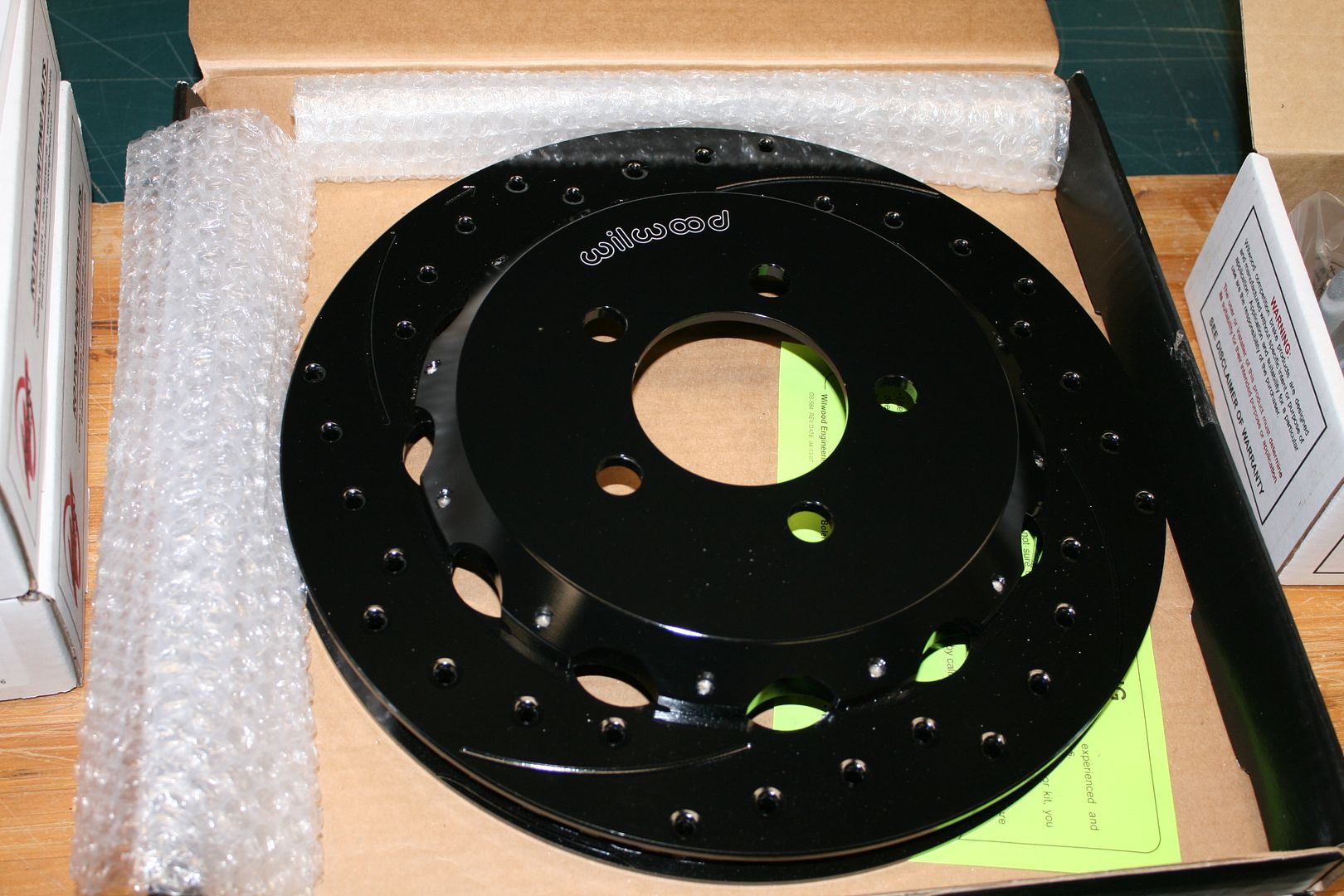
OK, last update, and a pretty big one. All of us Anniversary Edition builders have been patiently (or maybe not so patiently) waiting for the special Wilwood brakes that are part of the package. This is the last backorder piece for me. I think others are in a similar position. Last Thursday, received an email from Jay at FF that I had a box on the way from Wilwood. I was a little disappointed to learn this was only the front brakes. But it’s progress. The box was scheduled to arrive on Wednesday, but yesterday look what the FedEx truck left for me:
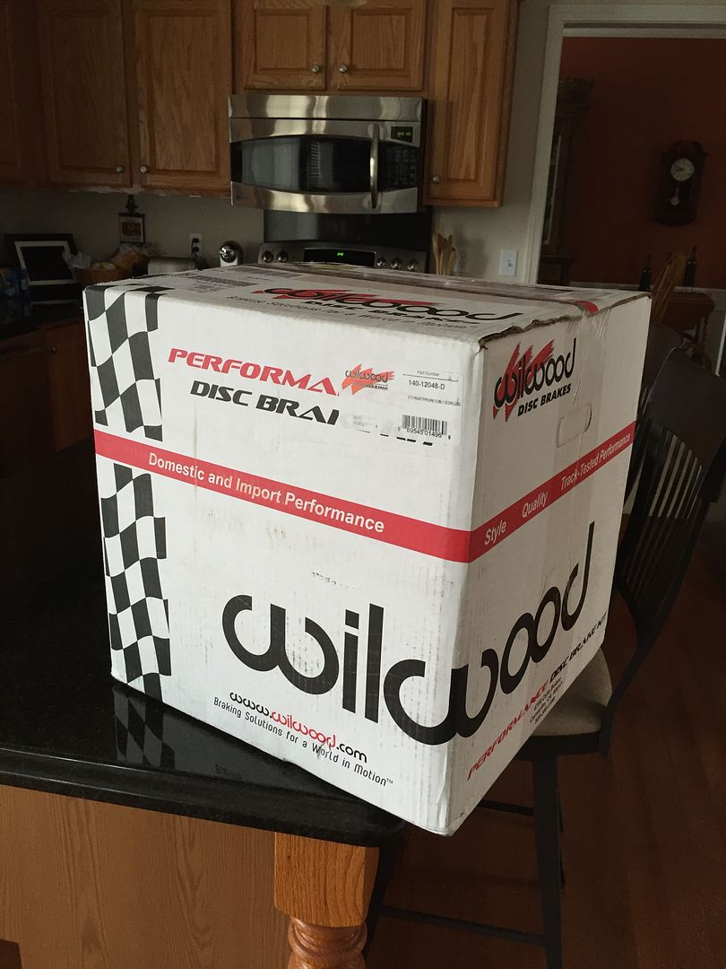
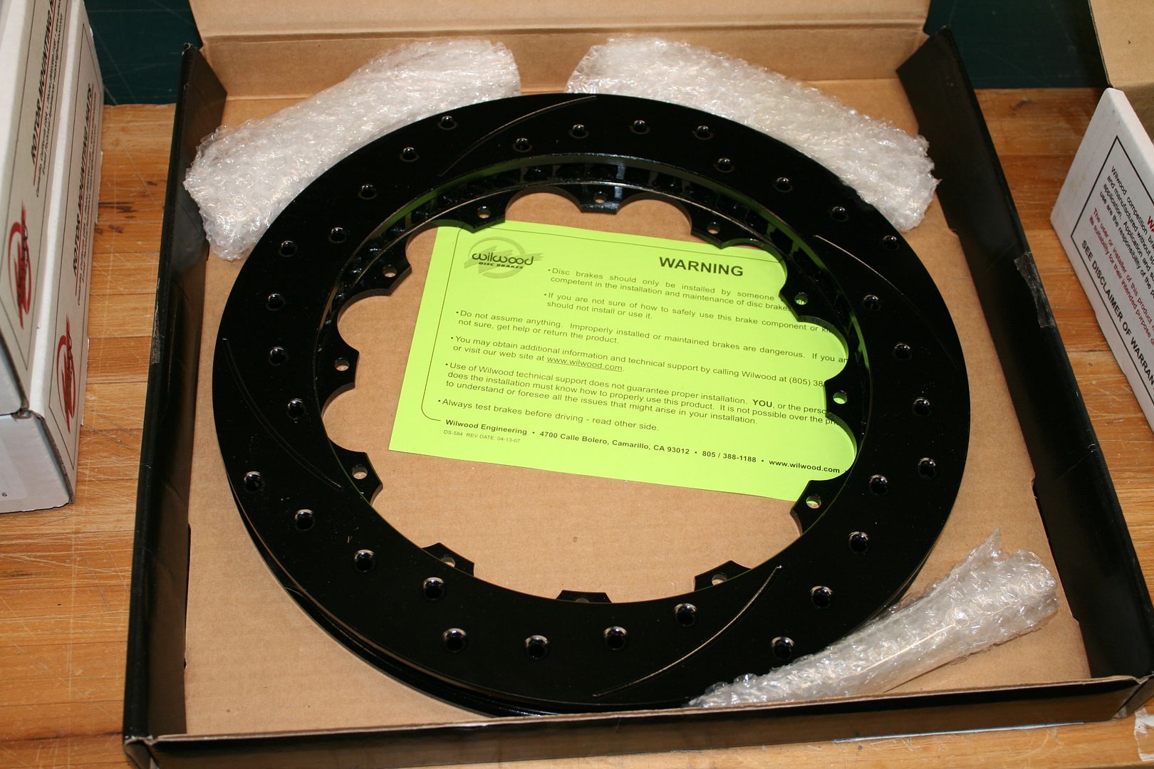
At first I was a little surprised that 48 pounds was only the front brakes. But after opening the box and checking everything out, now I’m not surprised. These things are meaty! I’ve just played around a little, mainly wanting to confirm everything fits. So far, so good. I’m going to get to learn how to do safety wires for the mounting bolts between the hat and the rotor. The instructions say the wire is “optional” (I guess that’s why they don’t include it…) but I will be installing it. Some on the way.
Rotor:
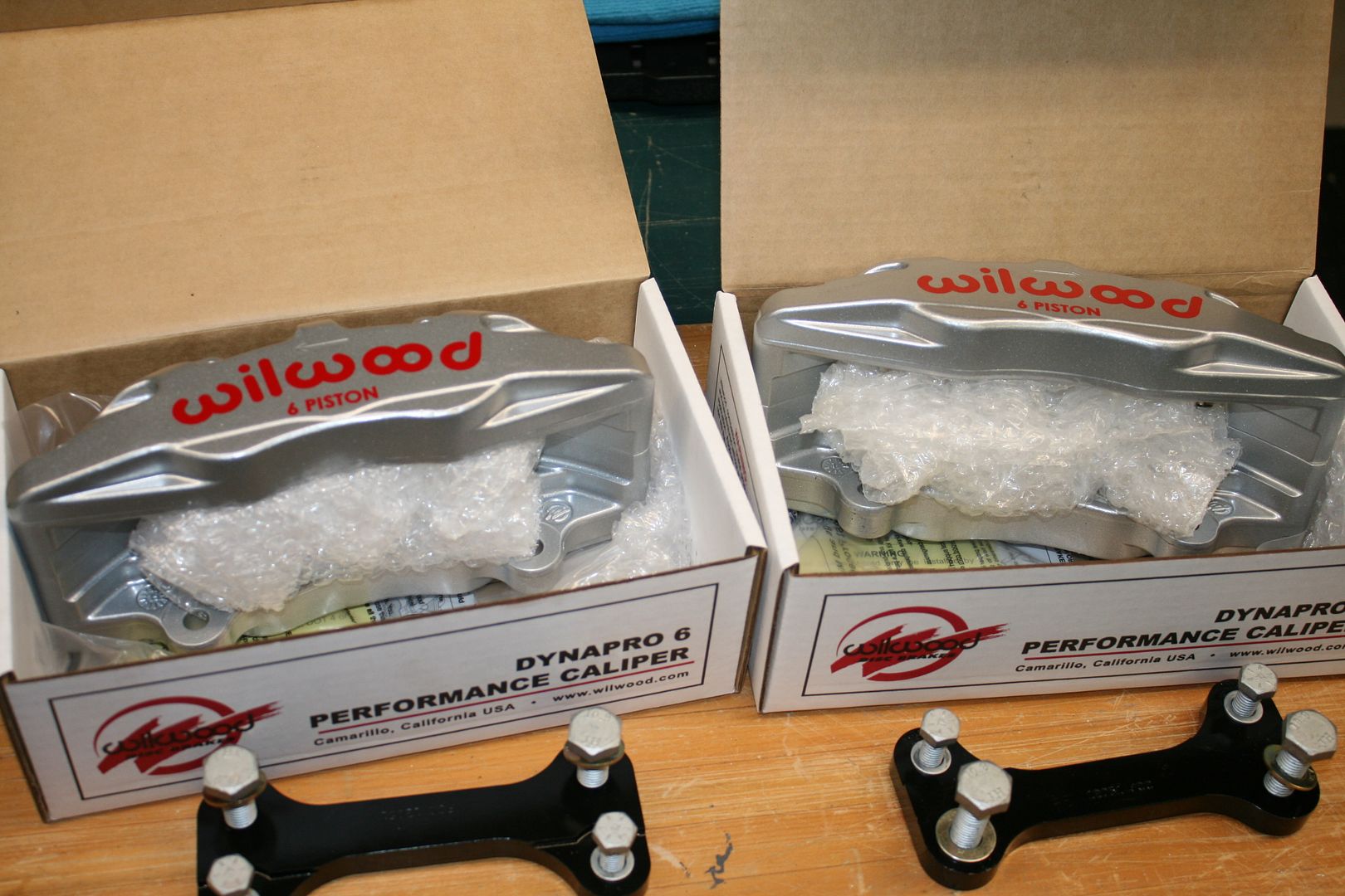
Calipers and mounting brackets:
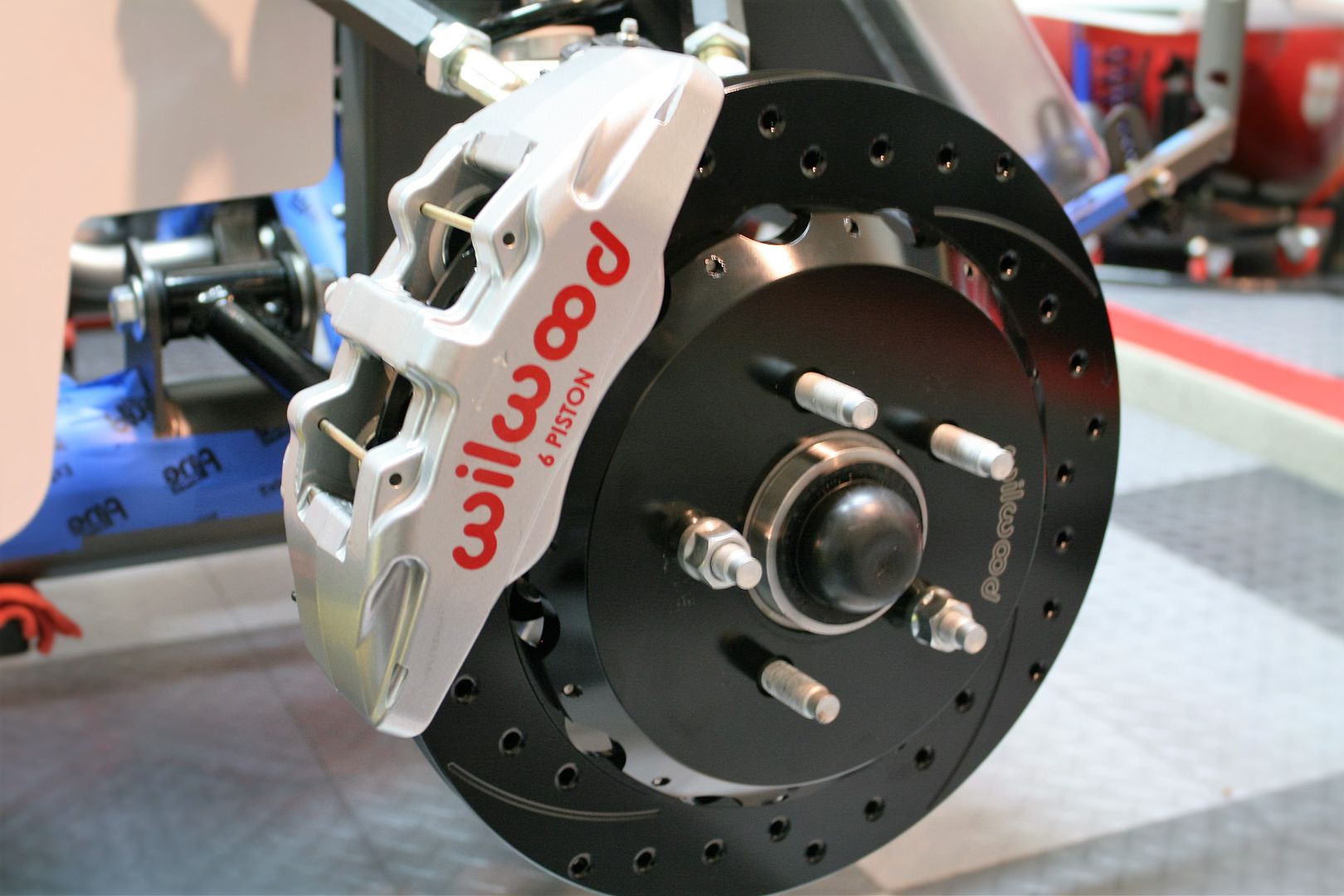
Temporarily installed one of the hats onto the rotor:
Did a quick check on the mounting. Other than it’s impossible to get a socket on the top mounting bracket to spindle bolt, all looks good:
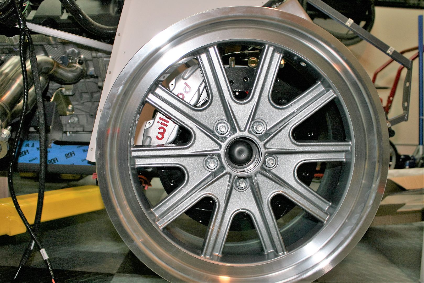
Had to drag out one of the 18 inch wheels and check the clearance. All good there too! They look nice in there.
Next update I should have them all mounted. No word yet on the back brakes. I’ve asked, but no answers yet. Onward.
Build 1: Mk3 Roadster #5125. Sold 11/08/2014.
Build 2: Mk4 Roadster #7750. Sold 04/10/2017.
Build Thread
Build 3: Mk4 Roadster 20th Anniversary #8674. Sold 09/07/2020.
Build Thread and
Video.
Build 4: Gen 3 Type 65 Coupe #59. Gen 3 Coyote. Legal 03/04/2020.
Build Thread and
Video
Build 5: 35 Hot Rod Truck #138. LS3 and 4L65E auto. Rcvd 01/05/2021. Legal 04/20/2023.
Build Thread. Sold 11/9/2023.
-
11-24-2015, 12:28 PM
#120
 Administrator

That glove box is amazing! Do you have a shrinker/stretcher you created those curved tabs with?
KILLER build so far!

FFR 5369 Pin Drive, IRS, Trigos, Torsen, Wilwoods, FMS BOSS 302 "B" cam , Mass-flo. CA SB100 (SPCN) Registered
Delivered 4/23/06. "Finished" 4/2012 (still not done!)
-
Post Thanks / Like - 0 Thanks, 1 Likes


 Thanks:
  Likes:


 Reply With Quote


 Real versions of these are available at Summit and elsewhere for not too much.


 Thanks.


 I anchor them with 3/16 inch aluminum rivets. The hole in the mount needs to be drilled out just slightly. Depending on the specific 3/16 rivet, some will drop down into the countersink. Others need to be adjusted. If so, I put them in the drill press, and with it turning a couple swipes with a file and they fit perfectly. I usually make up 10-20 at a time, and just have them available. Makes a really clean and strong installation.


