-


Frame Dolly and Body Buck Plans for the FFR MkIV Roadster
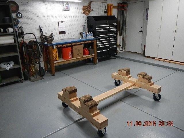
I have had two requests in the past week for my "Frame Dolly" plan. While I am honored that people seem to like it, and it works well, I must clarify that this isn't even close to "my" design. I got the basic idea from another forum member, sadly I can't remember who or I would give them credit. I started with their idea, modified it for my own needs and height, and this is the end product:
So for those that would like a "plan" for a simple frame dolly, here is mine.
Parts List:
1- 4"x6"x10'
1- 2"x6"x10'
4- Large casters with locks. I used 6", 600lb capacity, HF wheels with no locks. Good size choice, Good weight limit. (2400lbs total. Enough for the car, though it never supported the car with the engine or transmission installed.) BAD choice not getting locking casters. I fought this thing to stay in one place. GET CASTERS WITH LOCKS!!
1- 2'x4' piece of 3/4" plywood.
3 1/2" Deck Screws
2” Deck Screws
16 – 2 ½” hex head lag screws
Wood glue.
Scraps of carpet for padding.
1. Cut off the 4"x6" into two 44" long pieces.
2. Cut the remain 4x6 material into four equal pieces of about 8" each.
3. Cut 5' off the 2"x6".
4. Cut four pieces 2"x6"x12". (Make Eight of these if you are taller and want the frame to be higher off the ground, or if you use smaller casters. You will need an additional four feet of 2x6 for this.)
5. Cut the remaining 1' of 2x6 into four equal 2x6x3" pieces.
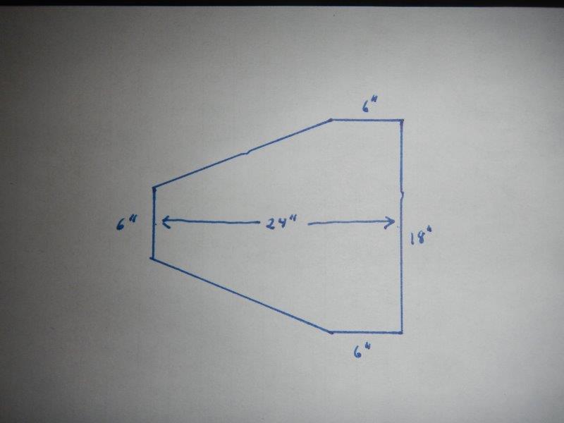
6. Cut the plywood into two pieces 18"x24". I cut the pieces in this way to create more workable space under the car next to the dolly:
7. Cut the remaining plywood into four pieces of ¾” plywood 6”x8” (Big enough to mount your casters to)
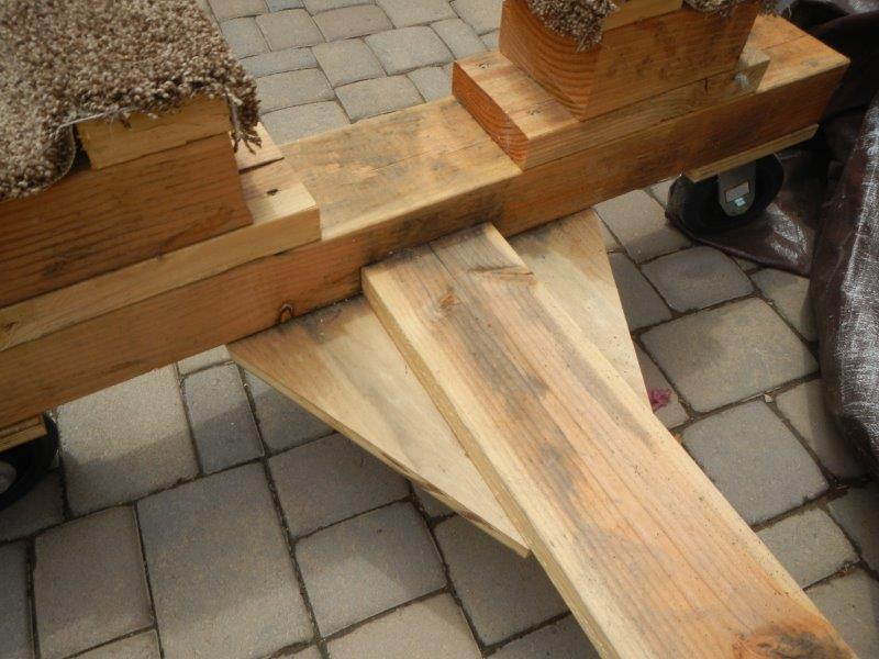
Start with the 44" long 4x6's. Find the center point at 22", then draw lines to create a half lap joint centered on the 44" length just wide enough for your 2x6x5'.
Cut out that lap joint area with either your circular saw or a table saw with a dado blade kit. (Be careful with this method! Ask me how I know!!  ) Cut this notch just deep enough to accommodate the thickness of the 2x6, approximately 1 5/8" deep. When you are done, your 2x6 should just fit into this notch. Glue and screw one end of the 5' 2x6 into each notch of the 4x6. While the 2x6 and notch are on the top (the dolly is upside down), Glue and screw the plywood pieces to the underside to completely encase the 2x6 and stabilize the dolly. When you have it all glued and screwed together, the end of your dolly should look like this:
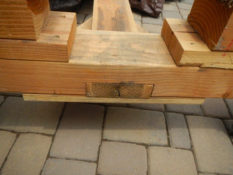
While the dolly is still upside down, glue and screw the four ¾” caster plates to the ends of the 4x6 on the same side of the 4x6 as the larger piece of plywood. Use 2 ½” lag screws to attach your casters to the caster plates. Turn the dolly right side up so it is now sitting on it’s wheels. Lock the casters in place
Make the frame support pieces:
Center the 12" 2x6 on the 8" 4x6, leaving 2" of overhang on each end. Glue and screw these pieces together. Repeat this process four times, one for each corner. If you want the frame to be higher off the ground, add one more 12" 2x6 to the stack. Turn the stack over, placing the 4x6 at the top. Glue and screw one of the 3" 2x6's on top of the 4x6 to create a notch. your frame will sit on the 4x6 and will be kept from moving by the side of the 3" 2x6. Mount the frame support stacks by gluing and screwing through the 2” extensions of the bottom most plate into the top of the 4x6. The frame rails are 24” on center apart. The vertical edges of the top 3” piece that will be on the inside of the main frame rails should be 19” apart. This will create the flat spots that the 4” main frame rails will sit on at the correct 24” on center location. Put small pieces of carpet over the top to protect the powder coated finish of the frame.
That’s pretty much it. If you like this, use it with my blessing. If you want to modify it for your own purposes, again, go forth in peace. Much thanks to whomever initially created this design. If you will PM me, I would be more than happy to give you credit. I just hope this helps someone make an easy working frame dolly. I found it worked exceptionally well for me. (With the exception of the non-locking casters!! Don’t make that mistake.)
*** EDIT *** 1/1/2018
Bill Haas' Body buck plan which I used, modified, then modified again is shown on posts 14-16 in this thread. Thank you, Bill, for this very helpful and detailed post. Your work continues to help others.
Last edited by Jazzman; 01-01-2018 at 04:31 PM.
-
Post Thanks / Like - 3 Thanks, 4 Likes
-
Senior Member

Thanks for posting Kevin. Could you provide some plans for one that fits a Gen 3 coupe...
MK4 #8900 - complete kit - Coyote, TKO600, IRS - Delivered 6/28/16 First Start 10/6/16 Go cart - 10/16/16 Build completed - 4/26/17 - 302 days to build my 302 CI Coyote Cobra - Registered and street legal 5/17/17
Build Thread
http://thefactoryfiveforum.com/showt...e-build-thread
PHIL 4:13 INSTAGRAM - @scottsrides
-
Senior Member

I've had a picture of a frame dolly, with dimensions, since before I started my build back in 2012. It's from a post back in 2007 on a different forum, but it worked great for my Mk4 frame. Problem is, I can't figure how to post it here. Tried to copy the picture and paste it into the post, but that doesn't seem to work. If someone knows what I'm doing wrong let me know and I'll get it posted.
Rick
-
On a roll

Rick (EZ$) - try this: go to the post you want and right click on the photo itself. you should get a pop up window with an option for "save image as...". Choose that one, save it someplace on your machine and then you should be able to move it/post it as you want.
Mk IV Roadster - #8650 - delivered 7-17-2015 - first start 7-28-2018 - first go-kart 10-13-2018 - licensed and on the road 9-9-19: body/paint completed 3-17-2020.
Complete kit / 2015 Coyote / TKO600 / IRS / Wilwood brakes / Mid-Shift mod / Power Steering / Heater and Seat Heaters / RT turn signal / Breeze radiator shroud and mount
-
Senior Member

You mean this pic?
Chassis dolly.jpg
818S/C : Chassis #25 with 06 WRX 2.5 turbo, ABS, cruise, PS, A/C, Apple CarPlay, rear camera, power windows & locks, leather & other complexities. Sold 10/19 with 5,800 miles.
Mk3 Roadster #6228 4.6L, T45, IRS, PS, PB, ABS, Cruise, Koni's, 17" Halibrands, red w/ silver - 9K miles then sold @ Barrett-Jackson Jan 2011 (got back cash spent).
-
Senior Member
That's the one Pete. I'm glad someone knows how to do this. I kept right clicking on the picture, clicking copy, and then going to the post, and right clicking and clicking on paste, and nothing happened. Al, I have the picture in my computer, and I still couldn't get it to work. I'll figure it out someday.
Rick
-
On a roll

Originally Posted by
wareaglescott

Thanks for posting Kevin. Could you provide some plans for one that fits a Gen 3 coupe...
Scott, Are you building a coupe now???
Mk IV Roadster - #8650 - delivered 7-17-2015 - first start 7-28-2018 - first go-kart 10-13-2018 - licensed and on the road 9-9-19: body/paint completed 3-17-2020.
Complete kit / 2015 Coyote / TKO600 / IRS / Wilwood brakes / Mid-Shift mod / Power Steering / Heater and Seat Heaters / RT turn signal / Breeze radiator shroud and mount
-
Senior Member

Thanks for this timely thread. I will be building one of these next weekend, and seeing plans from others makes it easy. I'm going to riff on the basic idea of Jazzman's detailed chassis dolly plan.
EZ$: Rick, why'd you add the two additional casters in the middle of each end? Just curious...
Thanks!
--Curt
-
Senior Member
Curt, that's not my design or picture. I found that on the other site about five years ago, but someone posted the picture with the dimensions back in 2007. I wish I could remember who it was cause it was a great design, and they should get the credit. I agree though that the extra wheels are not necessary to carry the frame, even once you get most of the other pieces mounted.
Rick
-
Senior Member
Curt, I built that chassis dolly 10 years ago for a MK3 and I probably did not need the casters in the middle. I still tend to overdo stuff, like those casters, but building our own cars makes many of us over-think and overdo, then think it over and do it over. Later, I re-did that dolly to hold an 818.
818S/C : Chassis #25 with 06 WRX 2.5 turbo, ABS, cruise, PS, A/C, Apple CarPlay, rear camera, power windows & locks, leather & other complexities. Sold 10/19 with 5,800 miles.
Mk3 Roadster #6228 4.6L, T45, IRS, PS, PB, ABS, Cruise, Koni's, 17" Halibrands, red w/ silver - 9K miles then sold @ Barrett-Jackson Jan 2011 (got back cash spent).
-
Senior Member
Oh, I know about over thinking things. Enjoy your 818 build.
Chassis dolly build to fill the time, waiting.
Thanks for the replies.
-
Junior Member

Nice work. Gonna have to keep this information for my Mk 4 build.
-
Thanks Jazzman. These are perfect.
-
Post Thanks / Like - 0 Thanks, 1 Likes
-
I just had a request for my "body buck plan". Just like the frame dolly, I stole . . . er . . . creatively acquired that plan from another builder. This time at least I can give credit where it is due. Way back in 2002, Bill Haas wrote this post "How to build a Body Buck for your Factory Five Roadster ver 2". Here is what he wrote:
How to build a Roadster Body Buck for a Factory Five Racing Roadster Roadster Kit - Ver. 2.0
By: Bill Haas
Updated: August 31, 2002
The following is a new detailed set of instructions on how to build the body buck for a Factory Five Racing (FFR) Roadster Replica kit. I am not a tech writer, so like most things you find for free there are sure to be some mistakes, so use these at your own risk. Drawings and a complete materials list, tools and supplies you will need are at the end of this document. I suggest that you take the materials list page with you when you go to the building supply place so you dont forget something (Yes, I had to make two trips).
I built my buck using a combination of several others plans and pictures that I found on the Roadster related forums on the Internet. When I was done I concluded that a few changes, updated drawings and more detail might be useful. Thats not a criticism of the fine writings and postings on this subject by others before me. About 2400 of us FFR builders have been the beneficiaries of the work, postings and pictures of people like Wade Chamberlain, Scott Brooke, John Baker and many many others. I figured for the non-carpenters or mechanically challenged people, more detail and pictures should help insure that what you create turns out to be a Buck and not a Doe.
Some of the changes in my instructions include: 1) increased stilt/leg height and reduced basic buck height to make more room under the buck for your chassis. 2) Completely new drawings. Over time, it seemed that minor errors and missing info had accumulated in some redraws that were available on the Internet. I also realized that the original FFR drawings didnt show several dimensions that us motor heads could use make the buck correctly (most of us were not geometry majors or carpenters).
Anyway, I called the factory to get a good clear copy of the original FFR spec sheet drawings that are in the back of the manual. I entered all the specs into my ESPRIT Cad/Cam software and bingo, it created a set of accurate drawings, where all the dimensions were present and the many line and arc intersect points actually met. ESPRIT was used to create the drawings at the end of this document. So that the buck drawings were as large as possible and thus easier to read, they show only the left side of Front and Rear buck faces. The right sides are just a mirror image. Yes, I work for DP Technology Corp, the developer of ESPRIT Cad/Cam software, so I need to get this plug in on the first page. Quite a few Racing Teams and NASCAR Winston Cup and IRL Chassis builders use our ESPRIT software so we do know a little about high performance cars. Take a look at www.dptechnology.com then click on motorsports on the left margin. The completed buck pictures that I included for reference in these instructions are ones I found on the various forums and Internet sites. Hopefully I didnt miss giving anyone credit.
If you are going to build only one buck, it is easier to just draw the dimensions directly on the OSB wood sheets rather than to make a full size set of paper templates. If you do want templates to survive several builds, like for your Car Club, I suggest drawing and cutting them from Tyvek. I have assumed that when there was a step that could be screwed up (like all the ones I messed up), I put down lots of detail, probably overkill.
Regards, Bill Haas, AKA Bill32 on the various Roadster forums
Southern California FFR 3358K
I can be contacted at wdhaas@earthlink.net or bill.haas@dptechnology.com
Getting Started
why stilts and wheels for the basic buck?
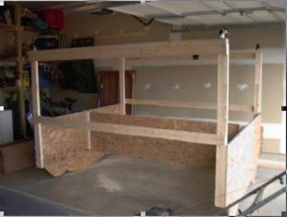
The object of the stilts is to make a buck that one person can easily roll around, is tall enough to allow storage of the Roadsters rolling chassis under it, and still be short enough so the whole thing fit through a 6 8 to 7 garage door opening. Actually, the buck comes out about 74 without the roadster body on it, so maybe 78 (6 6) with body on. You dont have to add the stilts, or the wheels, but making the stilts are only a little extra work.
Important Stuff about building the basic buck. When cutting the straight edges of the OSB, use a straight edge or chalk line to mark the lines and a skill saw to cut these, not the jigsaw. Straight cuts will help you end up with legs that are mounted straight up and down. This will also help hid the fact that you may have been nipping at the beer before you finished. Keep in mind that part of the purpose of the buck is so you can roll it out of the garage onto the driveway so that all the neighbors and passersby will see the cool thing you are creating and stop to ask questions. So, it better look good. AND, you dont want your friends laughing about the drunken Giraffe you built and ask you if the Roadster will turn out any better!
The pictures give you a pretty good idea what you are trying to build and what different people have done. Note that some of the bucks in the pictures have one pair of legs on the inside of an end face and the other pair on the outside of the end. I recommend that you put both pairs of legs on the inside faces so you dont have to shorten the length of the center OSB support to less than 8 ft. These instructions assume you are putting the legs on the inside of the end faces.
Read all before you start: I suggest that you read all the way through these instructions once before you start so you have a good overall understanding. The build will take 2 people about 2+ hours, not counting the time to go get the materials or any time spent drinking beer while discussing what the next step should be. It is fairly well documented that if you drink the beer during the build, it takes longer and you make more mistakes. But it is also known that after a couple of brews the mistakes dont seem to bother you much either. Everything will be put together using wood glue and course thread dry wall screws, not nails. Dry wall screws pull the pieces together tight so the glue will set up strong. This is important as rolling the buck around tends to loosen things up if you use nails.
There are some pros and cons to using glue
. the Pros are, it wont come apart easily
the Cons are, it wont come apart easily. Dont be skimpy with the glue and dont get carried away either. It is the glue that will ultimately hold the thing together. Pre-drill all screw holes through the OSB sheets, but do not drill the holes through into the 2 x 4s. These OSB holes need to be large enough for the screw to push through the OSB by hand, but not be sloppy.
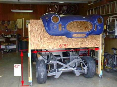
Scott Brookes buck, showing my dimension mod to height.
(width dimension, 77 in. (65) is the internal width not counting the legs.
The 42 height is from ground to bottom edge of buck end face)
Making the two buck ends faces. Start off by cutting 2 of the 4 ft. x 8 ft. OSB sheets down to 80 inches in length. That is the width of the finished buck end plates that the body sits on (see drawings at the end). Dont be confused by the 6 5 width ( 77 in.) measurement in the previous picture. That 77 in. is the inside distance between the legs (Thus, 77 in. + 2 legs at 1 ½ in. thick ea. = 80 inches, the total outside width).
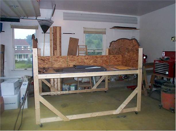
Wade Chamberlains buck. Note he made his shelves the full width of each side of the buck.
My plans have shelves only 1 foot wide, but any width will work.
Leave the 3rd sheet of OSB full length (8 ft.). This sheet you need to cut it in half lengthwise so you end up with two pieces 8 ft. x 2 ft. Now, take one of these 2 ft. wide pieces and cut it in half lengthwise again so you get two 12 wide by 8 ft pieces from it. The 2 ft wide piece is the vertical center support that ties the front and rear OSB ends together, the two 12 wide pieces will be the long shelves, which also provide racking strength to the buck. These shelves are not yet on some of the bucks in the pictures.
Either draw out the buck end dimensions directly on the OSB sheets, or if your created full size templates, layout the Front drawing on one of the OSB sheets you cut to 80 inches, and draw its outline on the OSB. Before you cut, do some final measuring. Measure twice, cut once! OK, you are ready to cut. Now, do the same with the Rear drawing on the other 80 in. OSB sheet.
After completing both panels above, draw a centerline down the front and rear panels from the top to bottom, on both sides. (the top meaning the upper sculptured edge the car will rest on). These lines will be used to align two vertical 2 x 4 supports for the center vertical OSB piece. To make these supports; take an 8 ft. 2 x 4 and cut off two 24 in. long pieces. These will be attached to the Front and Rear OSB panels per the following steps.
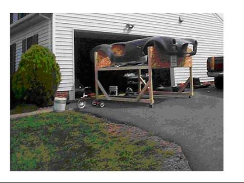
(this design used shorter diagonal cross braces which go from the middle of the leg to the lower rail, rather than my style of braces that go from the upper rail to the lower rail. Either method works OK. I dont know if the tricycle is the official buck tow vehicle, but it seems a little underpowered to me.)
-
Post Thanks / Like - 0 Thanks, 2 Likes
-
Part 2:
Making the center support. Making screw holes for the two vertical supports: Hold or clamp the Rear OSB end piece flat against the Front one, aligning the bottom edges. This will allow you to drill screw holes in both at the same time. Now, drill a single line of holes for the 1 5/8 in. drywall screws 1 inch from one side of the vertical line (doesn’t make any difference which side of the line you use). Space the holes about 5 inches apart and make sure you drill through both sheets.
Now put wood glue on the flat side of one of the 24 in. 2 x 4 vertical supports you cut in the previous instructions. Hold it up to the line you drew on the inside of the Front buck OSB sheet and screw in the 1 5/8 in drywall screws from the outside of the OSB sheet. Align the bottom of the 2 x 4 with the bottom edge of the OSB sheet. Do the same with the other 24 in. 2 x 4 support on the other OSB end sheet. Remember that these front and rear vertical 2 x 4 supports’ positions mirror each other on the inside faces (the holes you drilled are a mirror image which is why we drilled both sheets together).
You are now ready to connect the two ends of the buck using the vertical center OSB piece (the 24 in x 8 ft piece as shown in the below picture), connecting it to the vertical supports you just attached to the end sheets. If you have a third pair of hands for a couple of minutes this will help. The center OSB sheet simply screws into the 1 ½ edge of the two vertical 2 x 4 supports you just attached, use glue and pre-drill the vertical OSB support sheet. Make sure that the bottom edge of the OSB center piece is flush with the bottom of the OSB end pieces.
The basic body buck shape is now done. The next steps are to make and install the legs.
The Legs and Rails.
Making Legs: First, turn the basic buck you have just completed upside down so the sculptured edges are down and the straight bottom edges are up. To begin, cut the two 10 ft. 2 x 4s in half so you have four 5 ft pieces. These will become the buck’s legs. You will later trim off the top of these legs to the correct height. Notice in the earlier picture that you want to have about 42 inches of open height under the buck so your rolling chassis will fit under it. We have to put a line across each leg 42 inches from the “ground”. This line is used to align the bottom edges of the buck ends. Your mark will therefore be at 42 inches less the height of the wheels. Some people put an 8 ft. 2x4 flat along the bottom of the bottom rails (see pics). I don’t think these are necessary as they add more weight, but you decide. If you do add these 2x4’s you have to subtract that 1 ½ inch from your 42 inches also.
Attaching Legs: To attached the legs to the front and rear OSB ends, pre-drill holes for the 1 5/8 drywall screws in the vertical edges of the OSB about ¾ of an inch from the outer edge, then glue and screw the legs on. The bottom edges of the buck ends line up with the 42 inch line. Yea, I know, I know, this may seem very obvious to you sawdust wizards, but to some people this may not be completely obvious, and I want everyone to end up with it done right the first time. And yes my friends do tell me I sometimes over explain, over explain, over explain…..
Picture of Scott Brooke’s buck
(Scotts’s shelf for storage and racking strength is not yet attached. Note this
buck has an optional 2x4 attached flat under the bottom, between the lower rail and the wheels)
Attaching the horizontal rails. These are full length 8 ft 2x4s. Drill two screw holes about 2 inches from both ends of all 4 rails. Using glue and the 2 ½ inch drywall screws, attach them to the outside of the legs as shown in the picture.
BEFORE you actually tighten the screws on the rails, use a carpenter’s square to check that the legs are square with the rails. That is, you have a right angle at the joint of the leg and rail. If you don’t have a square, you can use a box or another piece of wood to hold next to the corner of the leg and end to see if they are square. If you don’t square this up and then tighten the screws, the whole contraption will look like a drunken cow, it will wobble when you move it, and it will confirm to all your visitors that you were already on your 2nd six pack at this point in the build!
Diagonal Cross Braces are to provide racking strength for the legs (not shown on all pictures). You are attaching these with the buck still upside down. You need to attach at least a couple of cross braces (I used only one on each side of the buck, some others use two on each side). Make these about 4 1/2 feet in length. These will go diagonally (about 45 degree angle) from the upper to lower rails. These go in the inside of the rails (same side as the legs). Attach these in the same manner as the rails, screws and glue. Check the legs-to-rails angle again for square before you tighten the brace screws. These cross braces will keep the whole assembly from racking fore and aft when you push it along. Remember that with the body on it, the buck will weigh 250 + lbs.
Wheel installation. You can either do this with the buck upside down, or roll the buck onto its side. Position the wheels on the end of the legs and mark the 4 screw holes. Drill small pilot holes for the #14 screws into the ends of the leg/rail ends so the wood doesn’t split when you put in these large screws.
For those not familiar with determining pilot hole sizes: Make sure the pilot holes are no bigger in diameter than screw shaft at the valley (bottom) of the threads. You can check this by holding a drill shaft along the side of the screw, hold it out at arms length. For screwing into wood, if you can just see the full depth of the threads sticking out beyond the drill shaft on both sides of the screw, the drill the right size. If you can’t see the full depth of the threads, the drill is too large in diameter.
Screw on the wheels and don’t over tighten, this is soft wood!! You are now ready to turn the buck right side up, so you will probably need some help. Lift it up far enough so you set it down gently onto its legs. Don’t let it crash down on them as will loosen the still damp glue joints and might break off the wheels.
Shelves. These are the two 12 in. by 8 ft. OSB pieces you cut earlier. From the remaining 2 x 4s, cut about 8 pieces, 8 inches in length each. These will be the under-shelf supports, 4 used on each shelf. You will place one on each end of the shelves and the other two along the vertical center OSB piece, spaced about evenly from the ends. Position these flat against the OSB so their bottom edge lines up along the bottom of the OSB. Pre-drill holes in OSB and then screw and glue the shelf supports in place. Now, set the 12 in x 8 ft. OSB shelves on top of these supports and screw and glue the shelves down to the supports. If you intend to put heavy items on the shelves, you can run a 2 x 4 x 8 ft support underneath the outside edge of the shelves (see pics). But be careful about putting too much weight on these shelves as it will make the buck heavy, hard to push, and could break off the wheels or legs. Cut off the upper end of the legs that are sticking up above the OSB on each corner of the buck.
The Foam Pipe insulation goes along the top sculptured edge on end faces of the buck where the body will rest. Open up the slit in the foam pieces and slip it in place. These will mold to the shape of actual body when it is on the buck. To keep the foam in place, drill holes every 18 inches along the sculptured edge, about 2 inches below that edge. Put the zip ties over the foam and through these holes to hold the foam in place.
Congratulations, you are now done, GOOD JOB, Go get beer.
Gentlemen’s Rules Note: It is specifically against the officially unwritten FFR Car Builder
Rules to open any champagne until after your kit arrives in the big Stewart Transport
Truck, you get it unloaded and onto the buck )
One last item before you open the BEER (or the trip to get more). At some point before putting the FFR body on the buck you will need to make the body support piece for the FFR body. This wood brace piece is to keep the body cockpit from flexing when you pick it up off the FFR frame and put it on the buck. This is described in the FFR manual in the “loading” section.
Credits, thanks and disclaimers
Thanks, recognition and well deserved credit to the many buck writers and builders who came long before me and the many forum posts where I found information and pictures on bucks, basic FFR build info, and examples of other people’s buck designs and kit builds.
Particular recognition and credits to:
Wade Chamberlain, http://www.quickkeys.com/Roadster/Default.htm
Has fantastic pictures of his build, very good close up pictures of detail.
John Baker, another great build site. http://Roadster.spintime.org/
Scott Brooke http://www.thebrkes.com/scott/Roadster/
DP Technology Corp, ESPRIT Cad/Cam software www.dptechnology.com .
My Dad, who helped with my buck. My son-in-law, Allen who is helping with the car build.
And my wife Claudia, who accepted the completely illogical reasoning behind my need to build a Roadster. Only a spouse can be that generous.
NOTE:
Last edited by Jazzman; 01-01-2018 at 04:48 PM.
-
Post Thanks / Like - 1 Thanks, 2 Likes
-
Part 3: Tools & supplies needed:
2 saw horses.
Tape measure, 12 ft
Chalk Line is handy for marking the OSB sheets for cutting
Skill saw
Jigsaw, use course blade
Electric or battery drill (for holes and putting in dry wall screws)
Phillips head bit for the drill
Carpenter’s Wood Glue, the good yellow stuff, NOT the cheap “all purpose” white stuff.
Carpenter’s Square and something you can use for a straight edge for drawing (2 x 4 will work).
Beer, preferably Bud Lite (I was unsure if this is a tool, required part or medical necessity, so I put it on both lists, feel free to buy it twice.)
Parts list: All of this will cost you around $100 or less including the wheels.
1. 3 sheets of OSB 4 ft. x 8 ft. . This is the stuff they use on houses for shear wall sheeting. (I used ½ inch thick and it worked great. Some others used 5/8” thick, but indicated it seemed thicker and heavier than needed.) This OSB stuff is usually under $8 a sheet. You could use plywood, but OSB is much stronger, easier to get good cuts on and won’t warp easily.
2. Ten 2” x 4” x 8 ft . You will only need 6 of these, unless you add the extra shelf supports and the long pieces under the legs and rails.
3. Two 2” x 4” x 10 ft - these get cut in half and become the legs.
4. 4 each caster wheels, recommend about 3 inch diameter or larger, total height including swivel about 4 inches or more. Don’t go smaller as they will not roll well at all.
5. Five each, 4 ft foam water pipe tubing insulation (usually comes in packages of 4 at Home Depot for about $4.00.
6. 10 inch or larger zip ties, about 16 of them, to hold foam insulation in place, or you could use some wire instead.
7. Small box - 1 5/8 in. course thread dry wall screws.
8. Small Box - 2 1/2 in. course thread dry wall screws.
9. 16 each - #14 size x 1 ¼ inch wood screws, philipps head, Check size of holes in wheel swivel.
10. Beer, optional (necessary), for back pain, best used when all above steps completed.
Last edited by Jazzman; 01-01-2018 at 04:49 PM.
-
Post Thanks / Like - 0 Thanks, 1 Likes
-
Senior Member

Great post(s)!!!! I can see myself following that plan very closely except for #10 in the tools and supplies list! 
-
Senior Member

Nice! Have seen several body bucks in various posts. Love the frame dolly!
-
I'm planning to build a frame dolly similar to the one in the first post of this thread for my MkIV kit that should be arriving in the next couple of weeks. However, I'm planning to roll the frame dolly (with frame/body) onto my four post lift so I need to make the legs wider than shown in the plan in order for the casters to be centered on the ramps of the lift. I need the casters to be 56" apart (so legs ~60" long vs. 44" as shown in the plan). My question is, will I run into interference issues between the legs and the bottom of the fiberglass body if I lengthen the legs? Do I need to raise the area that supports the 4" frame members to avoid interference? I can't tell from any photos I've seen if the lower edge of the fiberglass body hangs below the 4" frame members, and/or whether the legs of the frame dolly would interfere with the body?
Thanks,
John
-
Senior Member
Originally Posted by
mach'er
Oh, I know about over thinking things. Enjoy your 818 build.
Chassis dolly build to fill the time, waiting.
Thanks for the replies.
Mach'er
I have a frame dolly I'm finished with. You are welcome to it if you want to drive over to Kildeer, IL It's a couple hour drive. Up to you.
Steve
2nd MK4 #10639 received 3-19-23. Wife's version. Street Snake - IRS, Willwoods, no roll bars, no hood scoop, no stripes, Blue Print EFI 306 with AOD trans, and under car exhaust. Ford Eruption Green with saddle leather interior.
1st build - Mk4 Roadster #9319, received 4-10-18. IL registration 8/6/19. Moser 8.8. 3 Link. Wilwood brakes. Blue Print 427, Holley 750, TKO 600, 0.64 OD. Paint Dec 2020. Ruby Red with Carbon Flash Black metallic stripes.
-
25th Anniversary #9772

-
One Available in Portland
I have a dolly frame and body buck if anyone in the PNW wants one.
-
Post Thanks / Like - 0 Thanks, 1 Likes
-
-
Thanks, This will help a great deal.
AROCK
-
RJD, this is AROCK located in Fredericksburg VA
-
Member

This thread is much appreciated. I wish I had thought about something like this years ago when I started building my reverse trike. I did most of the work on the ground or on my bike lift until it was too heavy for my tiny compressor. I’m still in the organizing and planning stage but this is something I can do until I’m ready to put in the order. Thank you all so much!
-
Has anyone here tried to lower the height of the bucks and thus lowering the whole rig? I have somewhat smaller garage doors so trying to keep it as low as possible. Looking at the pictures here, the body seems to sit at least 10in above the bottom edge of the OSB sheets of the buck. Anyone tried just trimming that off?
-
Senior Member

Last edited by GTBradley; 11-23-2021 at 10:01 PM.
Bradley
Build thread - Mk4, Coyote, IRS, Wilwood brakes, old-style soft top and accessories.
The distance between "finished" and finished is literally infinite.
-
Post Thanks / Like - 0 Thanks, 2 Likes
-
Senior Member

Not sure why everyone so over thinks a buck? Factory Five just sets them outside on the ground.
I hung mine directly to the ceiling with hooks in the wheel wells, was like that for a long time, not a single issues.
Mrk III, 331 stroker, Borla stack injection, T5, 3:55 IRS, Power steering and brakes. Kleiner body & paint
-
Post Thanks / Like - 0 Thanks, 2 Likes
-
Originally Posted by
rich grsc
Not sure why everyone so over thinks a buck? Factory Five just sets them outside on the ground.
I hung mine directly to the ceiling with hooks in the wheel wells, was like that for a long time, not a single issues.
I wondered about that. Our kit is coming and I have seen several people doing what you did and wondered if there would be any deformation of the body. Thank you @jazzman. I am going to build the dolly before my wood shop is converted to a car shop.


 Thanks:
  Likes:


 Reply With Quote


