-
11-24-2015, 12:44 PM
#121
Senior Member


Originally Posted by
David Hodgkins

That glove box is amazing! Do you have a shrinker/stretcher you created those curved tabs with?
KILLER build so far!

Thanks David! Nope, no fancy metal working tools here. I just bent the box around the wood forms, the front ring, and the full back using a hammer. With all the relief cuts for the tabs, the 28 gauge galvanized steel is pretty malleable. It's from the heating/cooling aisle at Home Depot, used for making air handling ducts. I found a piece for about $8 that was way more than enough.
Last edited by edwardb; 11-24-2015 at 12:47 PM.
Build 1: Mk3 Roadster #5125. Sold 11/08/2014.
Build 2: Mk4 Roadster #7750. Sold 04/10/2017.
Build Thread
Build 3: Mk4 Roadster 20th Anniversary #8674. Sold 09/07/2020.
Build Thread and
Video.
Build 4: Gen 3 Type 65 Coupe #59. Gen 3 Coyote. Legal 03/04/2020.
Build Thread and
Video
Build 5: 35 Hot Rod Truck #138. LS3 and 4L65E auto. Rcvd 01/05/2021. Legal 04/20/2023.
Build Thread. Sold 11/9/2023.
-
11-24-2015, 08:33 PM
#122
Senior Member

Wow pretty nice work Edward, that dash is impressive. I'm still waiting on brakes, axles and latches. Your making some serious progress on your build. I'm going to have to put some decent hours in having a few days off coming up. Have u decided what rubber your putting on. Was reading the recommended was 225/35 and 315/30's? Cheers
-
11-24-2015, 08:59 PM
#123
Senior Member


Originally Posted by
Paul_M

Wow pretty nice work Edward, that dash is impressive. I'm still waiting on brakes, axles and latches. Your making some serious progress on your build. I'm going to have to put some decent hours in having a few days off coming up. Have u decided what rubber your putting on. Was reading the recommended was 225/35 and 315/30's? Cheers
I'm a ways away from buying tires. No advantage to having them until I'm ready to make it a roller, and they don't get better with age. Right now, I'll most likely go with the same tires FF has on the Anniversary protoptye: Toyo Proxes R888, with 255/35ZR18 fronts and 315/30ZR18 rears. There are some other brands to look at as well. Nitto NT-01's, Goodrich Rivals or Falken 615K's, to name a couple.
Hopefully you meant 255's for the front, not 225's. That's a little narrow.
Build 1: Mk3 Roadster #5125. Sold 11/08/2014.
Build 2: Mk4 Roadster #7750. Sold 04/10/2017.
Build Thread
Build 3: Mk4 Roadster 20th Anniversary #8674. Sold 09/07/2020.
Build Thread and
Video.
Build 4: Gen 3 Type 65 Coupe #59. Gen 3 Coyote. Legal 03/04/2020.
Build Thread and
Video
Build 5: 35 Hot Rod Truck #138. LS3 and 4L65E auto. Rcvd 01/05/2021. Legal 04/20/2023.
Build Thread. Sold 11/9/2023.
-
11-25-2015, 02:50 AM
#124
Very nice work on the glove box and dash. If you want to try to still use the McMaster hinges, drive the hinge pin out and reversed the mounting to make it more compact.
-
11-25-2015, 05:37 AM
#125
Senior Member

Yep, typo there meant 255. Decided I'm going to chrome the door, trunk and hood hinges. Should match the interior door latches nicely. Found someone to powder coat all the other steel parts gloss black and then the panels gray to match the frame. Given the pace of your build I was thinking you'd be driving before the snow! CHeers
-
11-26-2015, 01:03 AM
#126
Member


Originally Posted by
Paul_M

Yep, typo there meant 255. Decided I'm going to chrome the door, trunk and hood hinges. Should match the interior door latches nicely. Found someone to powder coat all the other steel parts gloss black and then the panels gray to match the frame. Given the pace of your build I was thinking you'd be driving before the snow! CHeers
PaulM if you are interested in a pair of Nitto's for the rear, I have a brand new pair of 315/30 ZR18 for sale at a discount. Never been on the pavement. PM me if you are interested
-
11-26-2015, 05:04 PM
#127
Senior Member

Thanks Bob, I'm still a long ways off from tires given my pace but will keep in mind. Got my front brakes yesterday, Jay says the rears are shipping on Dec 9th and my axels next week, so will only be waiting for the latches. Managed to get the upper control arms on, Edward you weren't kidding when you said was tight. I drilled out the frame holes and had to use the dremel on one section as it was hitting a weld but they are in. I seem to be missing the rear sway bar frame mounts so I'll have to wait for those now before moving on with IRS.
Want to wish all you fellow builders and your families a Happy Thanksgiving! Cheers
-
Post Thanks / Like - 1 Thanks, 0 Likes
-
11-27-2015, 02:10 PM
#128
Senior Member

Hey guys, anyone have the front sway bar installation instructions for our 20th kit they could send me? I found some online but those date 2011, seem right but just want to be sure. Many Thank
-
11-27-2015, 02:36 PM
#129
Senior Member


Originally Posted by
Paul_M

Hey guys, anyone have the front sway bar installation instructions for our 20th kit they could send me? I found some online but those date 2011, seem right but just want to be sure. Many Thank
I have front sway bar, rear sway bar, and IRS installation instructions. All are .PDF files. PM your email address and tell me what you need. For the front sway bar, the document I have is dated 2015. I don't think something from 2011 would be right.
Build 1: Mk3 Roadster #5125. Sold 11/08/2014.
Build 2: Mk4 Roadster #7750. Sold 04/10/2017.
Build Thread
Build 3: Mk4 Roadster 20th Anniversary #8674. Sold 09/07/2020.
Build Thread and
Video.
Build 4: Gen 3 Type 65 Coupe #59. Gen 3 Coyote. Legal 03/04/2020.
Build Thread and
Video
Build 5: 35 Hot Rod Truck #138. LS3 and 4L65E auto. Rcvd 01/05/2021. Legal 04/20/2023.
Build Thread. Sold 11/9/2023.
-
11-28-2015, 01:19 AM
#130
Senior Member

Great build so far; very detailed. I like how you made the glove box, but especially how you provide part numbers and suppliers. Great work! Although I'm building a Coupe, your build is giving me some ideas.
I'm sending you a PM for the PDF files. I'm interested to see if I can add at least the sway bars to my build. Thanks.
Carlos
FFR Coupe #0635; Ford 347ci, Tremec TKO500, 8.8 rear end w/ 3.27:1 gears, Cobra/SVO brakes
-
11-28-2015, 04:33 PM
#131
Senior Member

Front Wilwoods Installed
This will be a short update by my long-winded standards. Finished installing the front Wilwood brakes this morning after receiving them earlier this week, so thought I would go ahead and post. This was probably one of the easiest steps in the build so far. Everything fit perfectly and the instructions from Wilwood were excellent. The quality of the parts seems outstanding. The one slight glitch was none of my sockets fit the top mounting adapter to spindle bolt. It’s supposed to be tightened to 60 ft-lbs, and needed to get a socket around it to set properly. The problem is there’s not enough clearance between the bolt head and where it fits into the spindle. A quick forum search found others had experienced the same problem. Some replaced the bolt with an Allen head cap screw. Others were able to find a socket that would fit. None of mine did. I dug an unused 3/4 inch socket out of an old tool box and spun it on the face of my disk sander until the diameter was reduced enough that it would fit into the available space. Reducing it from 1.00 inch to .960 inch was all it took.
The hats are attached to the rotors with twelve 1/4 inch bolts each. The instructions say they should be installed with red Loctite and optionally safety wired. I know by experience how easy it is to snap off 1/4 inch bolts when red Loctite is used. So I used just a small dab on each one and torqued to the specified 155 in-lbs, and decided to go ahead and safety wire them. Probably not required for my intended street driving and cruising, but I wanted to give it a try since I've never done safety wires before. Picked up the safety wire twisting pliers at a local tool store (interesting tool…) and some .032 safety wire from Aircraft Spruce. I printed the referenced Wilwood safety wire instructions and watched a bunch of YouTube videos. After too much turkey and football, my brother-in-law and I sat down and took a shot at it. The first ones took awhile, and there were several do-overs. But then kind of got the hang of it and finished the first rotor. Then later finished the second one relatively quickly. The rear brakes are assembled exactly the same way, so I’ll get some more practice once they arrive.
Two down, two to go.
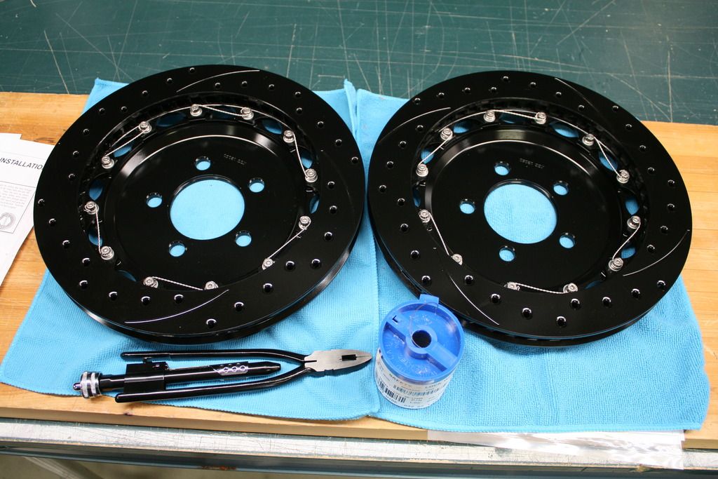
Closer view. Don’t look too close.
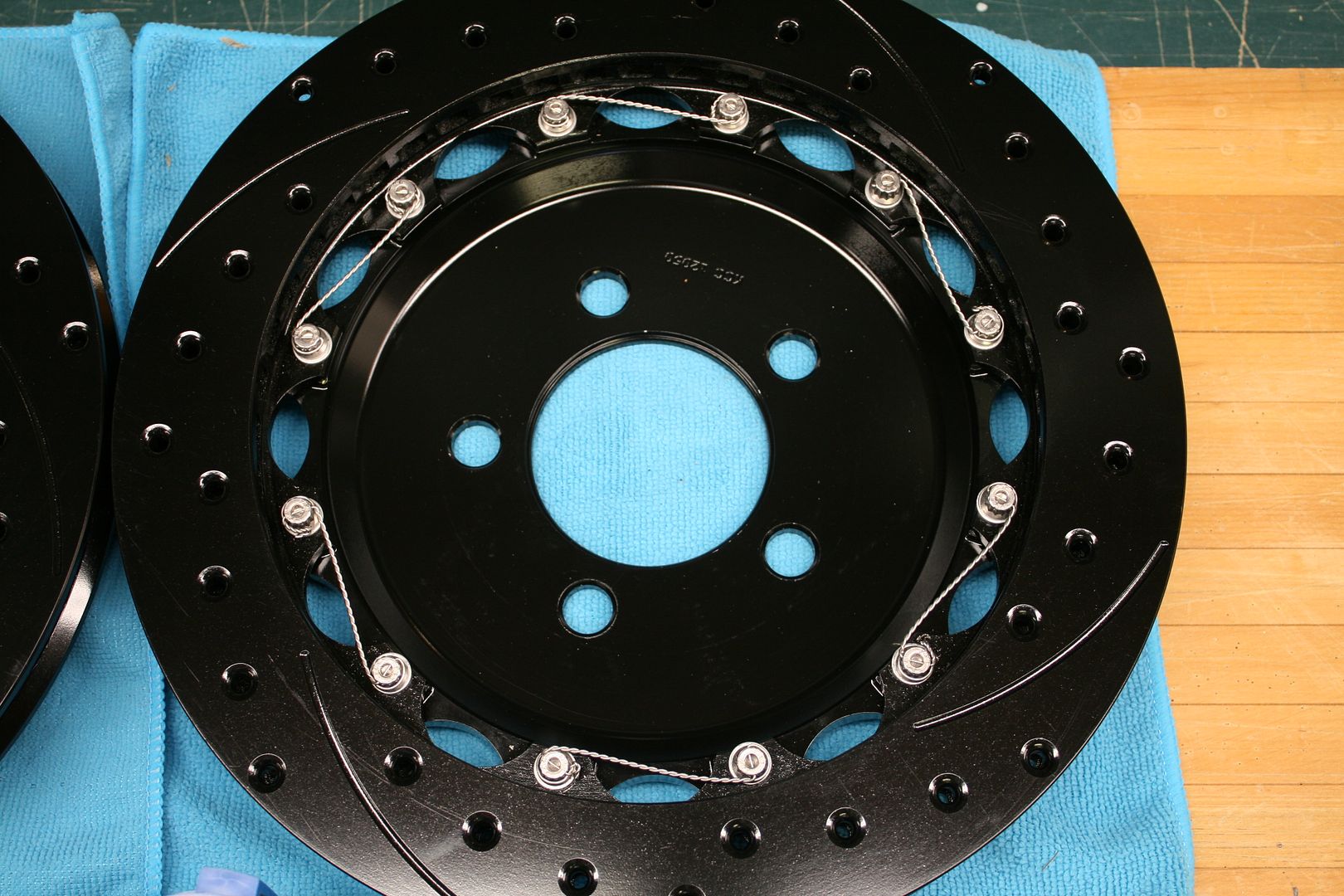
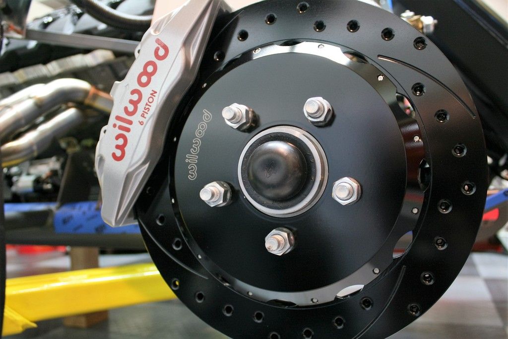
With the rotors assembled and mounted on the chassis, mounted and torqued the mounting bracket and then the calipers. It’s necessary to center the caliper using provided shims (washers). Mine took two of the thicker ones all the way around and they were perfectly centered. Then installed the pads, and installed the caliper for the last time.
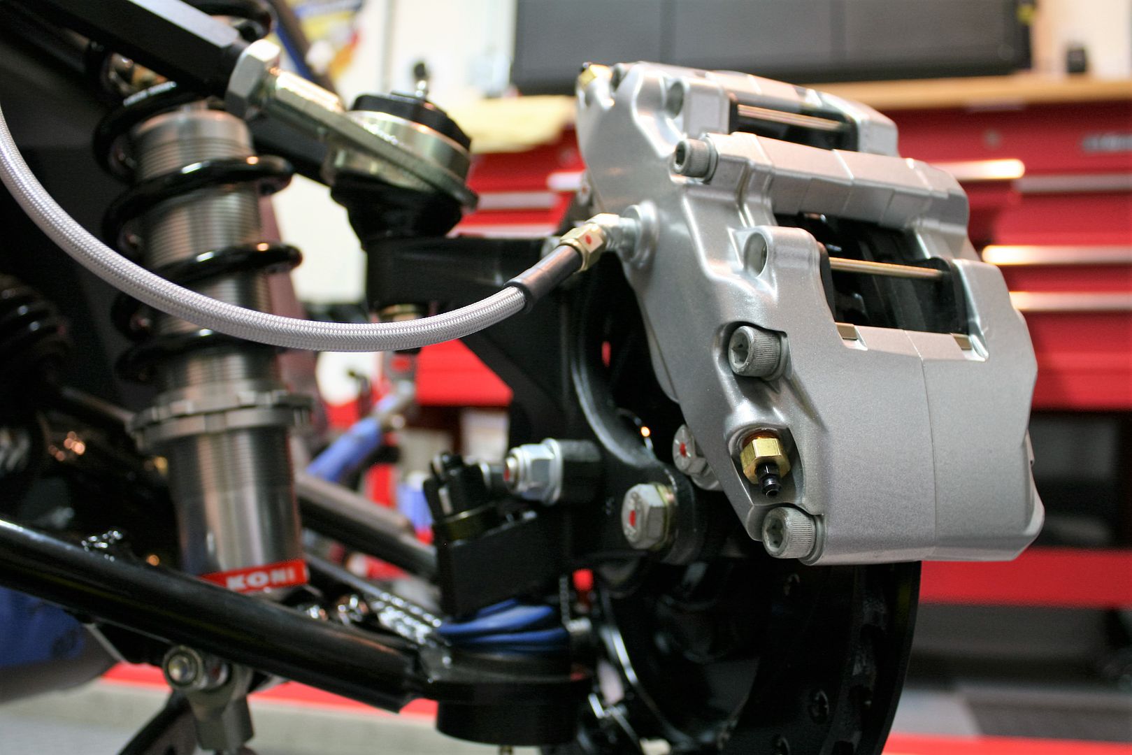
Last step was the stainless flex lines. I decided the flex lines worked best with the fittings in the calipers pointed down. Since it’s an NPT fitting into the caliper, I used Loctite 567 sealant on the threads. Just a light coat and kept it several threads away from the end. Then riveted the mounting plates and fittings into the F-panel openings. This is the same spot I’ve used for my other builds and I think is pretty typical. Then installed the flex lines and tightened the fittings with a flare nut wrench. No sealant on these threads! Turned the steering wheel lock-to-lock to confirm everything stayed where I wanted it, and called it done.
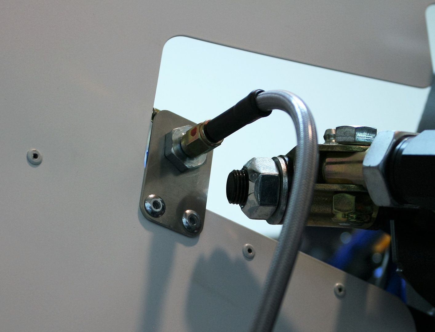
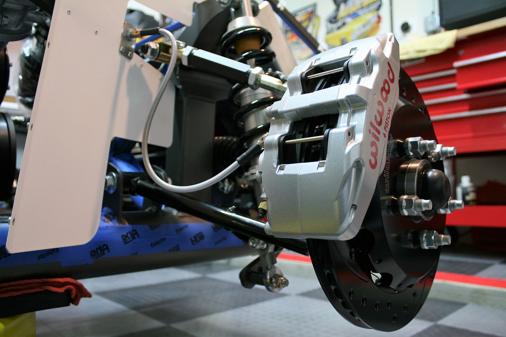
The rear brakes are currently promised to ship December 9. Hopefully that will happen. In the meantime, my shipment of 2015 Mustang GT radiator hoses is schedule for delivery on Monday. So hopefully my next update will show those installed along with the Moroso surge tank.
Last edited by edwardb; 11-28-2015 at 05:00 PM.
Build 1: Mk3 Roadster #5125. Sold 11/08/2014.
Build 2: Mk4 Roadster #7750. Sold 04/10/2017.
Build Thread
Build 3: Mk4 Roadster 20th Anniversary #8674. Sold 09/07/2020.
Build Thread and
Video.
Build 4: Gen 3 Type 65 Coupe #59. Gen 3 Coyote. Legal 03/04/2020.
Build Thread and
Video
Build 5: 35 Hot Rod Truck #138. LS3 and 4L65E auto. Rcvd 01/05/2021. Legal 04/20/2023.
Build Thread. Sold 11/9/2023.
-
11-28-2015, 04:59 PM
#132
Senior Member

Nice job safety-wiring the rotors, being your first time doing so. Am I seeing double, or do your calipers have bleeders on both ends? If not, remember that the bleeder should be on top, in order to let air out from the brake lines. I'm sure you know that, but sometimes we all can miss the simplest steps (especially when we're tired).
Carlos
FFR Coupe #0635; Ford 347ci, Tremec TKO500, 8.8 rear end w/ 3.27:1 gears, Cobra/SVO brakes
-
11-28-2015, 05:08 PM
#133
Senior Member


Originally Posted by
Carlos C

Nice job safety-wiring the rotors, being your first time doing so. Am I seeing double, or do your calipers have bleeders on both ends? If not, remember that the bleeder should be on top, in order to let air out from the brake lines. I'm sure you know that, but sometimes we all can miss the simplest steps (especially when we're tired).
Carlos
Thanks! Yes, I know how bleeders are supposed to go.  These style rotors and calipers are directional, so they have to go on specific sides. You can see the arrow just above the Wilwood name on the caliper in a couple of the pics. And yes, the calipers do have bleeders on both top and bottom. The Wilwood instructions properly explain that once installed only the top ones are used for bleeding.
Last edited by edwardb; 11-28-2015 at 05:13 PM.
Build 1: Mk3 Roadster #5125. Sold 11/08/2014.
Build 2: Mk4 Roadster #7750. Sold 04/10/2017.
Build Thread
Build 3: Mk4 Roadster 20th Anniversary #8674. Sold 09/07/2020.
Build Thread and
Video.
Build 4: Gen 3 Type 65 Coupe #59. Gen 3 Coyote. Legal 03/04/2020.
Build Thread and
Video
Build 5: 35 Hot Rod Truck #138. LS3 and 4L65E auto. Rcvd 01/05/2021. Legal 04/20/2023.
Build Thread. Sold 11/9/2023.
-
11-28-2015, 05:26 PM
#134
Senior Member

Well, I guess Wilwood makes it fool-proof, so even someone like me won't screw it up...
Carlos
FFR Coupe #0635; Ford 347ci, Tremec TKO500, 8.8 rear end w/ 3.27:1 gears, Cobra/SVO brakes
-
11-29-2015, 02:10 PM
#135
Senior Member

Edward, great job on the brakes. My fronts came on Wed, ordered the wires and twisting tool so will give it a shot next week.
I'm ordering the Russ Thompson trunk kit, has anyone decided on installing a battery box as well, seems to be nice one which sits just above / behind the rear center section?
-
11-29-2015, 05:12 PM
#136
Senior Member


Originally Posted by
Paul_M

Edward, great job on the brakes. My fronts came on Wed, ordered the wires and twisting tool so will give it a shot next week.
I'm ordering the Russ Thompson trunk kit, has anyone decided on installing a battery box as well, seems to be nice one which sits just above / behind the rear center section?
Good luck with the safety wires. I didn't find it too hard after I got the hang of it. Once you figure out the technique and proper routing, the biggest challenge IMO is that the bolt heads you're wiring are recessed down inside the rotor. So it can be challenging to feed the wire through the bolts. I know it's for a reason, but the safety wire is surprisingly stiff. Good luck and let's see those pictures when you're done.
For the battery, no question with the limited trunk space it makes sense to get it out of the trunk. The FFMetals rear trunk box is a nice setup, and many have used it. I'm planning to use the Breeze Automotive front battery box. Used it on my last build and like it very much. I'm almost certain the front box will fit OK, but I'm waiting until I have the radiator hoses, expansion tank, and power steering installed. It's getting pretty congested up there, so just want to be sure. Plan B would be to use the FFMetals rear trunk box.
Last edited by edwardb; 12-14-2015 at 08:00 AM.
Build 1: Mk3 Roadster #5125. Sold 11/08/2014.
Build 2: Mk4 Roadster #7750. Sold 04/10/2017.
Build Thread
Build 3: Mk4 Roadster 20th Anniversary #8674. Sold 09/07/2020.
Build Thread and
Video.
Build 4: Gen 3 Type 65 Coupe #59. Gen 3 Coyote. Legal 03/04/2020.
Build Thread and
Video
Build 5: 35 Hot Rod Truck #138. LS3 and 4L65E auto. Rcvd 01/05/2021. Legal 04/20/2023.
Build Thread. Sold 11/9/2023.
-
11-29-2015, 06:20 PM
#137
Senior Member

I think putting it up front makes sense if it fits. Breeze looks like a decent setup. I also have a 64 MGB, that originally came with 2 6 volts just behind the rear seat, now it has as 12v battery in the trunk, would like it out of there but there's no space. Just thinking that even if I didn't use the battery box for the battery, it's a nice compartment to store some extra fluids in the trunk so they don't spill....I'm thinking I'll install the FFMetal box and if I fit the battery up front great, otherwise it's got a nice spot in the trunk.
-
12-02-2015, 07:49 PM
#138
Senior Member

Hey Edward, quick question for you. In the process of installing the Breeze PS rack with the solid offset rack mounting kit. Did you have to grind down the frame mounts at all from interference from the boot? It seems really close so just wanted to check or did you rotate the solid bushings a little? Many thanks
-
12-02-2015, 08:33 PM
#139
Edwardb can answer too, but I have the same step and I did need to grind down some of the mounts per the included instructions.
-
Post Thanks / Like - 0 Thanks, 1 Likes
-
12-02-2015, 08:56 PM
#140
Senior Member


Originally Posted by
Paul_M

Hey Edward, quick question for you. In the process of installing the Breeze PS rack with the solid offset rack mounting kit. Did you have to grind down the frame mounts at all from interference from the boot? It seems really close so just wanted to check or did you rotate the solid bushings a little? Many thanks

Originally Posted by
RRussellTx

Edwardb can answer too, but I have the same step and I did need to grind down some of the mounts per the included instructions.
Really? I didn't grind anything down. Check the pics of the two sides in post #9 previously. The offset bushings should be installed with the large shoulder on the back (engine compartment side) and with the offset holes oriented towards the top. This slightly moves the rack toward the front and down. As a result, the boots touch the large frame member just slightly and the front LCA mounting ear just slightly. The frame member you can't do anything about anyway. Without the offset bushings moving the rack forward though some guys do get pretty good interference there. The trimming shown in the Breeze instructions is to the LCA mounting ears. But they're lower profile than they used to be. Personally, I don't think it's necessary to create any additional clearance. Keep in mind the suspension is hanging right now and the tie rods pointing down. At ride height, the tie rods will be almost parallel to the ground, moving the boot away from the LCA mounting ear interference.
Last edited by edwardb; 12-06-2015 at 10:28 AM.
Reason: Correction. Rack moves down not up.
Build 1: Mk3 Roadster #5125. Sold 11/08/2014.
Build 2: Mk4 Roadster #7750. Sold 04/10/2017.
Build Thread
Build 3: Mk4 Roadster 20th Anniversary #8674. Sold 09/07/2020.
Build Thread and
Video.
Build 4: Gen 3 Type 65 Coupe #59. Gen 3 Coyote. Legal 03/04/2020.
Build Thread and
Video
Build 5: 35 Hot Rod Truck #138. LS3 and 4L65E auto. Rcvd 01/05/2021. Legal 04/20/2023.
Build Thread. Sold 11/9/2023.
-
12-02-2015, 09:03 PM
#141
Senior Member

Thanks guys, Yep have the bushings installed correctly with the hole on the top. Edward from looking at your photos it didn't look like you had to grind anything but just wanted to ask to be sure as I can't seem to get it lined up. Will trying adjusting the solid spacers and keep trying. Cheers
-
12-02-2015, 09:09 PM
#142
Member


Originally Posted by
edwardb

This will be a short update by my long-winded standards. Finished installing the front Wilwood brakes this morning after receiving them earlier this week, so thought I would go ahead and post. This was probably one of the easiest steps in the build so far. Everything fit perfectly and the instructions from Wilwood were excellent. The quality of the parts seems outstanding. The one slight glitch was none of my sockets fit the top mounting adapter to spindle bolt. It’s supposed to be tightened to 60 ft-lbs, and needed to get a socket around it to set properly. The problem is there’s not enough clearance between the bolt head and where it fits into the spindle. A quick forum search found others had experienced the same problem. Some replaced the bolt with an Allen head cap screw. Others were able to find a socket that would fit. None of mine did. I dug an unused 3/4 inch socket out of an old tool box and spun it on the face of my disk sander until the diameter was reduced enough that it would fit into the available space. Reducing it from 1.00 inch to .960 inch was all it took.
The hats are attached to the rotors with twelve 1/4 inch bolts each. The instructions say they should be installed with red Loctite and optionally safety wired. I know by experience how easy it is to snap off 1/4 inch bolts when red Loctite is used. So I used just a small dab on each one and torqued to the specified 155 in-lbs, and decided to go ahead and safety wire them. Probably not required for my intended street driving and cruising, but I wanted to give it a try since I've never done safety wires before. Picked up the safety wire twisting pliers at a local tool store (interesting tool…) and some .032 safety wire from Aircraft Spruce. I printed the referenced Wilwood safety wire instructions and watched a bunch of YouTube videos. After too much turkey and football, my brother-in-law and I sat down and took a shot at it. The first ones took awhile, and there were several do-overs. But then kind of got the hang of it and finished the first rotor. Then later finished the second one relatively quickly. The rear brakes are assembled exactly the same way, so I’ll get some more practice once they arrive.
Two down, two to go.

Closer view. Don’t look too close.

With the rotors assembled and mounted on the chassis, mounted and torqued the mounting bracket and then the calipers. It’s necessary to center the caliper using provided shims (washers). Mine took two of the thicker ones all the way around and they were perfectly centered. Then installed the pads, and installed the caliper for the last time.

Last step was the stainless flex lines. I decided the flex lines worked best with the fittings in the calipers pointed down. Since it’s an NPT fitting into the caliper, I used Loctite 567 sealant on the threads. Just a light coat and kept it several threads away from the end. Then riveted the mounting plates and fittings into the F-panel openings. This is the same spot I’ve used for my other builds and I think is pretty typical. Then installed the flex lines and tightened the fittings with a flare nut wrench. No sealant on these threads! Turned the steering wheel lock-to-lock to confirm everything stayed where I wanted it, and called it done.


The rear brakes are currently promised to ship December 9. Hopefully that will happen. In the meantime, my shipment of 2015 Mustang GT radiator hoses is schedule for delivery on Monday. So hopefully my next update will show those installed along with the Moroso surge tank.
Bob C here, 20th Anniv. No.2. Lots of promises from FFR on Wilwood shipments but as of today, no tracking no., no shipment. :-(
-
12-05-2015, 11:59 AM
#143
Senior Member

Coyote Radiator and Coolant Tank Update
This week I’ve nearly completed the installation and prove-out of the radiator and coolant expansion tank hook-ups. As mentioned in an earlier update, I decided to go with the Mustang radiator and coolant setup versus the FF described setup using the T-filler and simple overflow tank. It’s slightly more complicated, but I think (hope) in the end is maybe better since it’s how our friendly Ford engineers intended the cooling system to work. Thanks to previous Coyote builds and postings, I was able to find most of the necessary information. So thanks for that! I will provide updated details including 2015 Mustang part numbers, since there are a few changes.
First order of business was the coolant expansion tank itself. Many previous builds have used the stock expansion tank. It wasn’t bad looking, fit OK, and the price is reasonable. However, the design was changed for the 2015 version, and it’s not so good looking. It’s been affectionately dubbed the turtle, and probably some not quite so nice. Here's a picture from a stock Mustang.
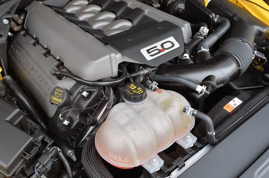
I chose instead to install the 2015 Mustang replacement tank pictured previously, a Moroso 63806. About an $85 upgrade ($70 vs. $155) but I’ll take it. I spent quite a bit of time figuring out the best location that met up with the hoses, cleared everything including the hood, etc. Then I fabricated some mounting brackets that matched the stock mounting locations on the Moroso tank. This is one of the times where I realize I will never build one of these in the 200-300 hour range as FF suggests. It’s pretty crazy how many hours you can spend coming up with the best design, fabricating the parts, completing the do-overs, etc. until all is good. The tank uses two bolts along the front and then a mounting receptacle on the bottom. I decided to hang it off the 3/4 inch upper radiator mounting tube and rest on the fan shroud. I first made some brackets out of .090 inch aluminum. But I wasn’t satisfied with the rigidity or the appearance of cracks/fracturing when making the bends. Even over a soft radius. So I switched up and made the brackets out of 1/8 thick x 1 inch wide mild steel strip stock from HD. Riveted them to the front of the 3/4 inch tube and wrapped around to the back where I installed 5/16 rivet nuts. For the mounting receptacle, made it out of three stacked pieces of the same material and bolted to the top of the fan shroud. Takes lots of time to get these just right, in the right location, etc. I sprayed with the same Rust-Oleum used for touch up in other places. Matches the Anniversary powder coat pretty OK, and nearly hidden when all done. There is the final mounting bracketry. Looks innocent enough, but lots of work there:
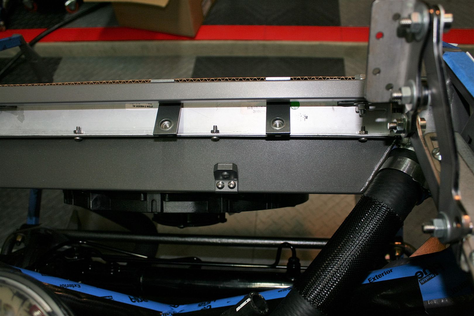
Then installed the upper radiator hose and lower tank hose. I’ll give the part numbers for this stuff at the end.
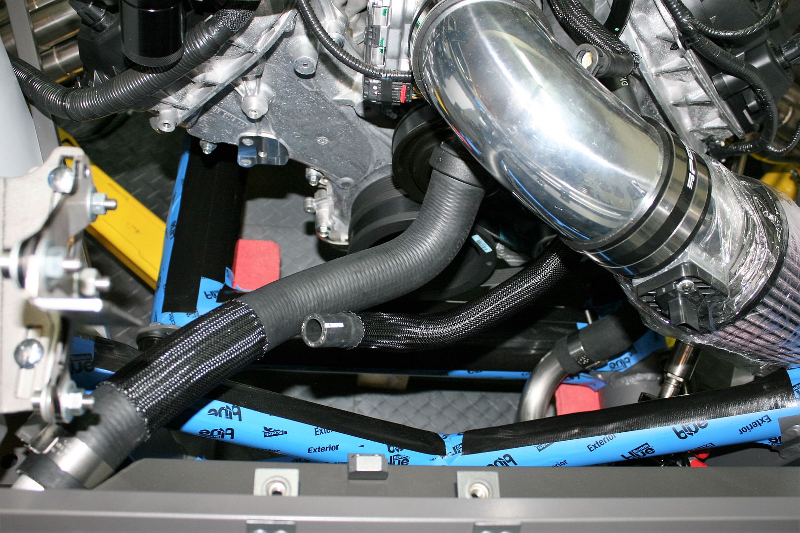
Then installed the tank.
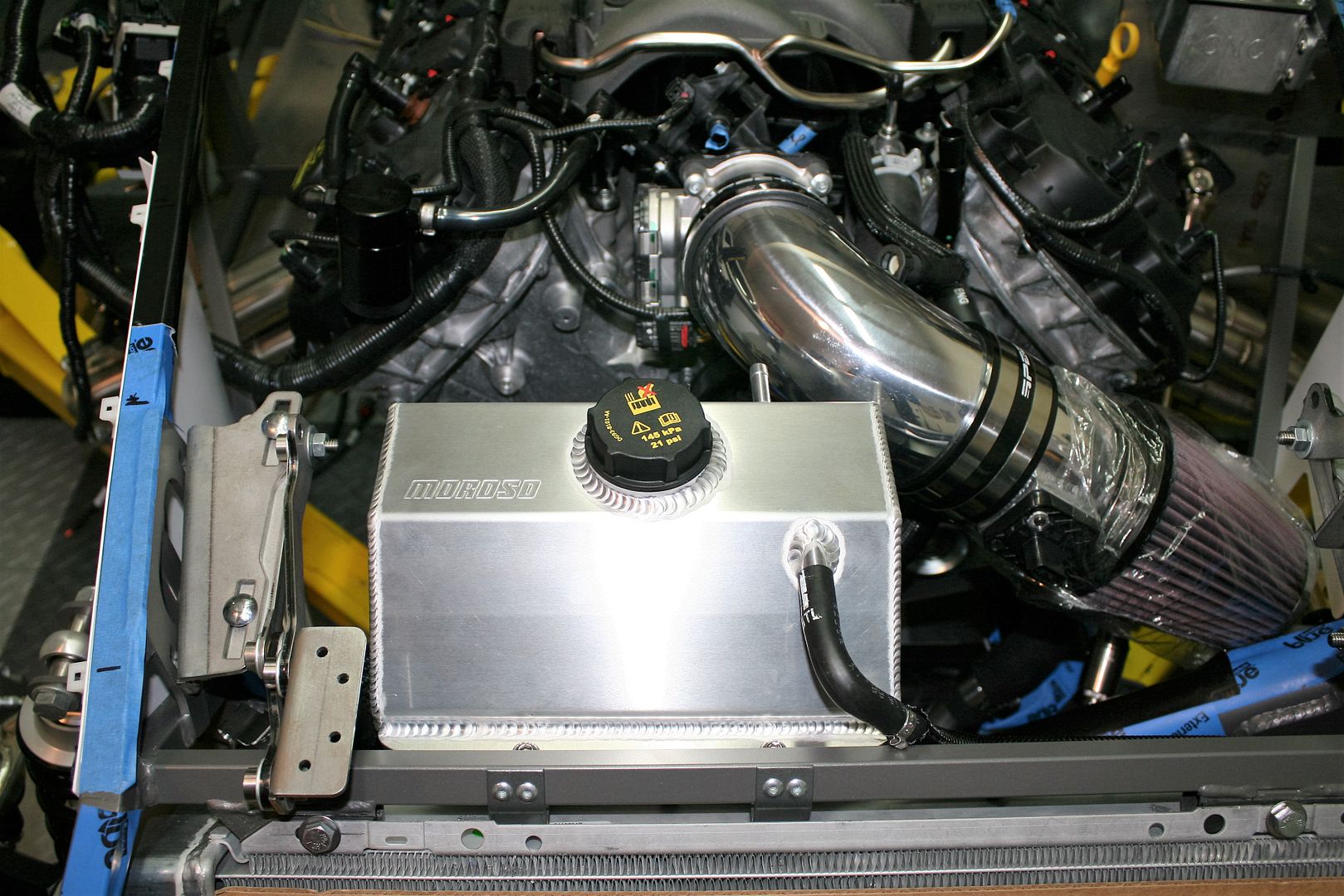
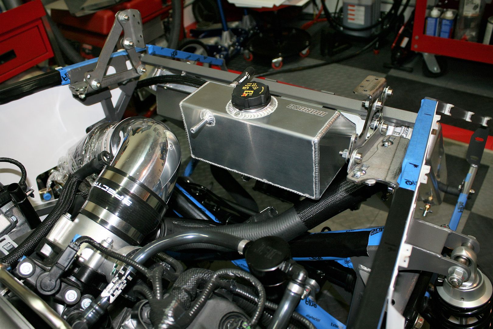
Looks good and I’m really happy with how it turned out. But even though I checked and double checked the dimensions, I began to have some doubt about whether I had it low enough to clear the hood. This is where it’s a huge luxury to have a completed Mk4 available. I measured exactly where the hood sits relative to the 3/4 inch hood frame, and set it in place on the new build.
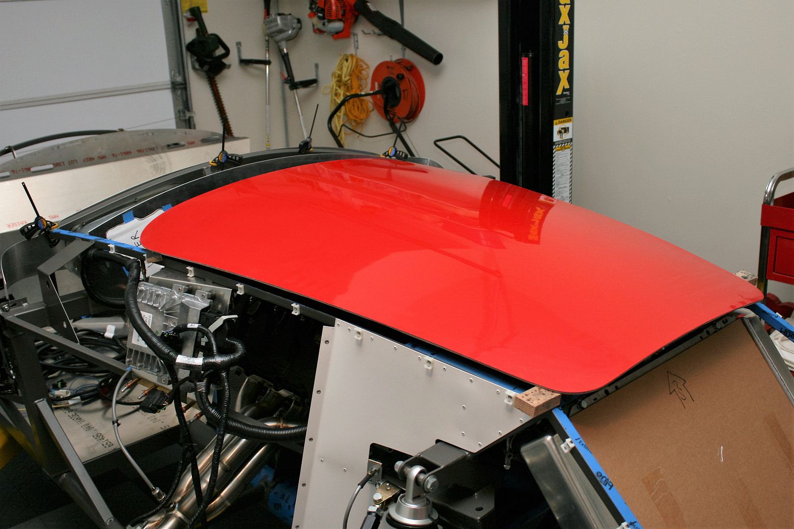
Confirmed that all was good. Tank and cap clear everything by an inch or so. I also noted that the larger and taller looking Coyote engine cover easily fits under the hood. I did find though that my also carefully calculated brake and clutch reservoirs were at basically zero clearance. So adjusted them down about 3/8 inch, and all is good there as well.
One of the hoses goes from the tank to the DS of the radiator. It’s required you remove the supplied petcock and replace with a hose barb. I used this Gardner-Westcott J9033 hose barb to pipe fitting from Summit. The Ford hose will need to be trimmed a bit to route properly. Note this hose has a one-way check valve at the tank end, which needs to be left alone. I guess that’s also why it’s a $50 part. Fortunately, the only one that expensive.
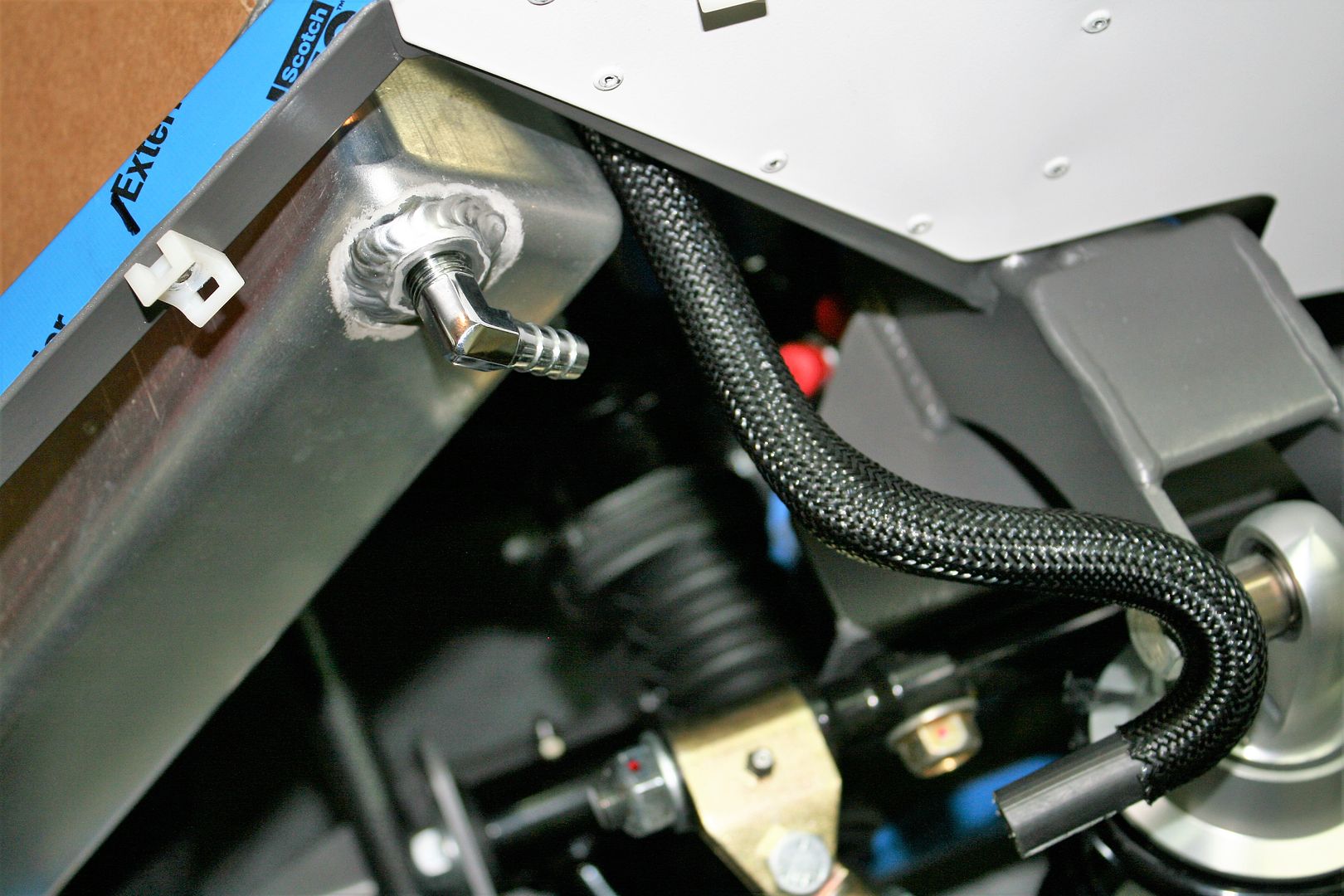
So for other 2015 Coyote builds if you are interested, here are the specific parts used:
CL3Z-8260-A or KM-5114 - Upper radiator hose. This is actually a 2012 F150 upper hose. As others have found, fits a bit better than the Mustang upper hose with its longer straight section. It has the quick disconnect on the engine side. Then cut it right at the sharp bend (check carefully!) and it plugs perfectly into the Afco upper connection.
FR3Z-8C289-B - Large tank bottom to engine.
FR3Z-8075-C – Hose from tank top/front to radiator, including one-way check valve described earlier.
DG9Z-8100-A - Stock Mustang reservoir cap. There are shiny aftermarket billet versions available, but this one at < $4 is a bargain.
FR3Z-8276-B - Hose from the overflow tank top/rear to the water neck near the throttle body. This part I was unable to find at any Ford part location. Several reported back they had no promise dates from Ford. Fortunately, it’s a simple hose, so will just make it up from stock material. The tank side is 3/8 inch ID, the engine side is 5/16 ID. So will require a reducer. But that’s easy.
Dayco 71713, Jegs 679-MB1040, Breeze Automotive 70612 – These are the parts used to make up the lower radiator hose. Previously described and pictured, but thought I would add the details here to make a complete list.
Finally, since I’m not installing a heater, I will make up a heater bypass hose as recommended by Ford Racing and mentioned before, rather than just capping the connections. I have the Gates 28504 heater hose connectors on the way, and will connect the inlet and outlet as recommended. There is supposed to be a 5/16 inch restrictor in the line, which I’m planning to fabricate since I can’t find anything that meets that description. No big deal. When all is said and done, the only remaining connections on the front of the engine not accounted for are the vacuum port and fuel evaporator intake tube just behind the throttle body. Those will be capped per the FF Coyote instructions.
I received an email directly from Wilwood this past Thursday apologizing for the Anniversary brake delays, and promising my rear brakes will ship next week arriving before the weekend. I understand all Anniversary buyers received a similar message. Hopefully they will deliver on their promises and we all can get this behind us. I’m looking forward to wrapping up the brake installation and moving to brake lines, fuel lines, etc.
Last edited by edwardb; 02-03-2016 at 11:01 AM.
Build 1: Mk3 Roadster #5125. Sold 11/08/2014.
Build 2: Mk4 Roadster #7750. Sold 04/10/2017.
Build Thread
Build 3: Mk4 Roadster 20th Anniversary #8674. Sold 09/07/2020.
Build Thread and
Video.
Build 4: Gen 3 Type 65 Coupe #59. Gen 3 Coyote. Legal 03/04/2020.
Build Thread and
Video
Build 5: 35 Hot Rod Truck #138. LS3 and 4L65E auto. Rcvd 01/05/2021. Legal 04/20/2023.
Build Thread. Sold 11/9/2023.
-
12-13-2015, 08:55 AM
#144
Senior Member

Update Including Rear Brakes
Friday I received my second 50 pound shipment from Wilwood. The rear brakes. This is a milestone on two fronts. First, I now have the complete set of long awaited Anniversary Edition Wilwood brakes. Second, it’s the last item on my shortage and/or missing list for my kit. I am now officially 100% complete.
Just a couple words about this subject. I am a huge fan of Factory Five products (obviously) and have the highest respect for the company and their products. They’ve allowed me to do something I’ve always wanted to do, and have a final product that I’m proud to own and a blast to show and drive. But I think they have room for improvement in the order fulfillment and delivery process. I fully realize the Anniversary Edition has some unique parts plus it is (I think) the first customer deliveries of the new 2015 Mustang IRS setup. So some shortages and delays maybe could be expected. But I was honestly pretty surprised when I saw the length of the backorder list when I picked up my kit, then added some items that were missing or just plain not accounted for. Everyone at FF was super friendly and helpful during every phone call and/or email. But it’s been six months since I ordered my kit, and four plus months since I picked it up. IMO that's really not acceptable. Especially the extended delays and missed promises for the Wilwood brakes. And they require 100% payment up front before taking delivery on anything. Hmm... But now it’s finally complete. I’m confident this will soon be a distant memory, and forgotten entirely once the build is completed. Owning and driving one of these will do that to you. But especially for first-time customers, this all has to be pretty disappointing. I spent my career doing multiple business continuous improvement projects. I would suggest this is something FF may want to focus on. Premium freight alone has to be significant. OK, enough about that. And I don’t want to turn my build thread into a rant on this subject. For me it’s done. I know there are others still waiting for a number of parts. Hopefully you too will soon get to this point.
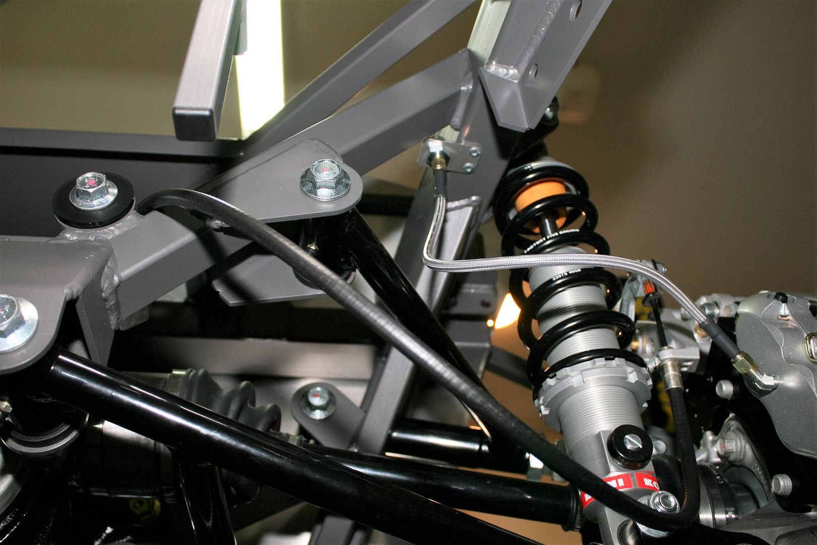
After completing the front brakes a couple weeks ago, the rear brakes went together very quickly. Again, the parts and instructions from Wilwood were top notch. Everything fit perfectly, and exactly like the instructions. I was interested (and maybe a little nervous) about the bracketry for the 2015 Mustang IRS knuckles, but it was fine. Not much to do except post some pictures.
The rears also use a separate rotor and hat assembly that is bolted together and optionally safety wired. I chose to do the safety wires like on the fronts. Getting a little better at it I guess. At least a little faster. Took me about an hour for each rotor and hat. The rotors are the same diameter as the fronts, but slightly thinner. The hats are different too. Different offset and don't require the adapter rings for the hub.
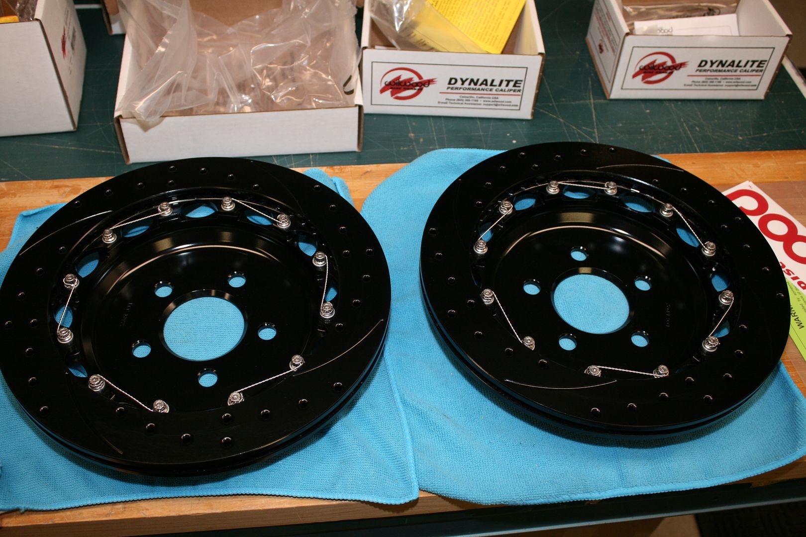
Shims are used to center the 4-piston caliper to the rotor, and also the height of the caliper on the mounting bracket. All was easy to set up just like described in the instructions. The rears use a separate parking brake caliper. So it’s quite an assembly when completed.
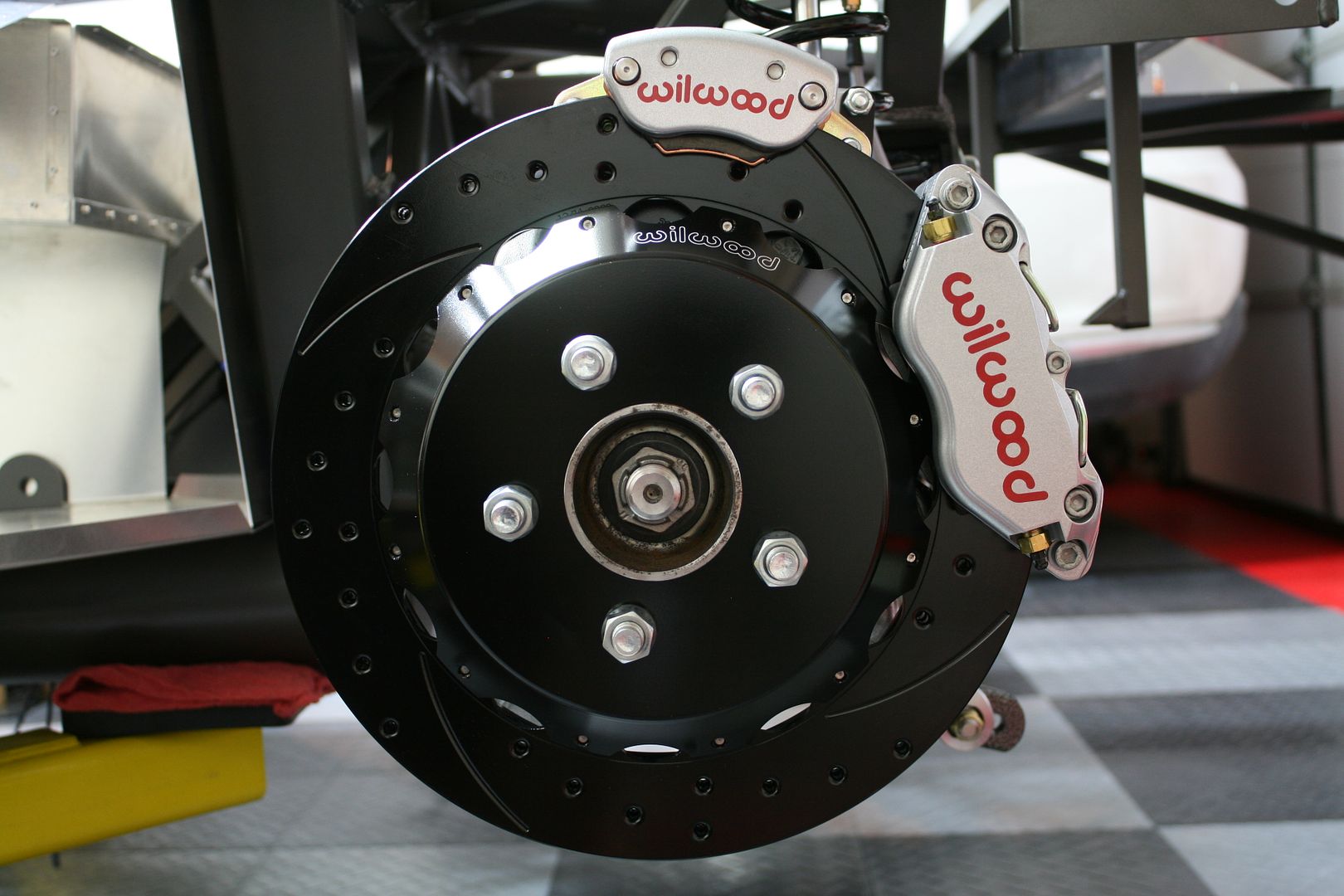
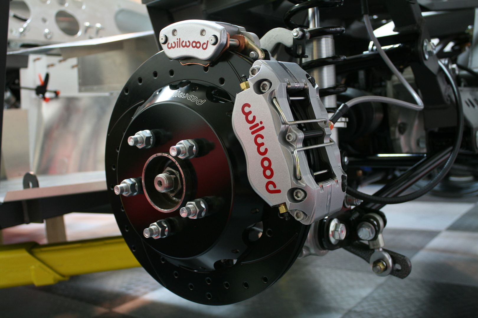
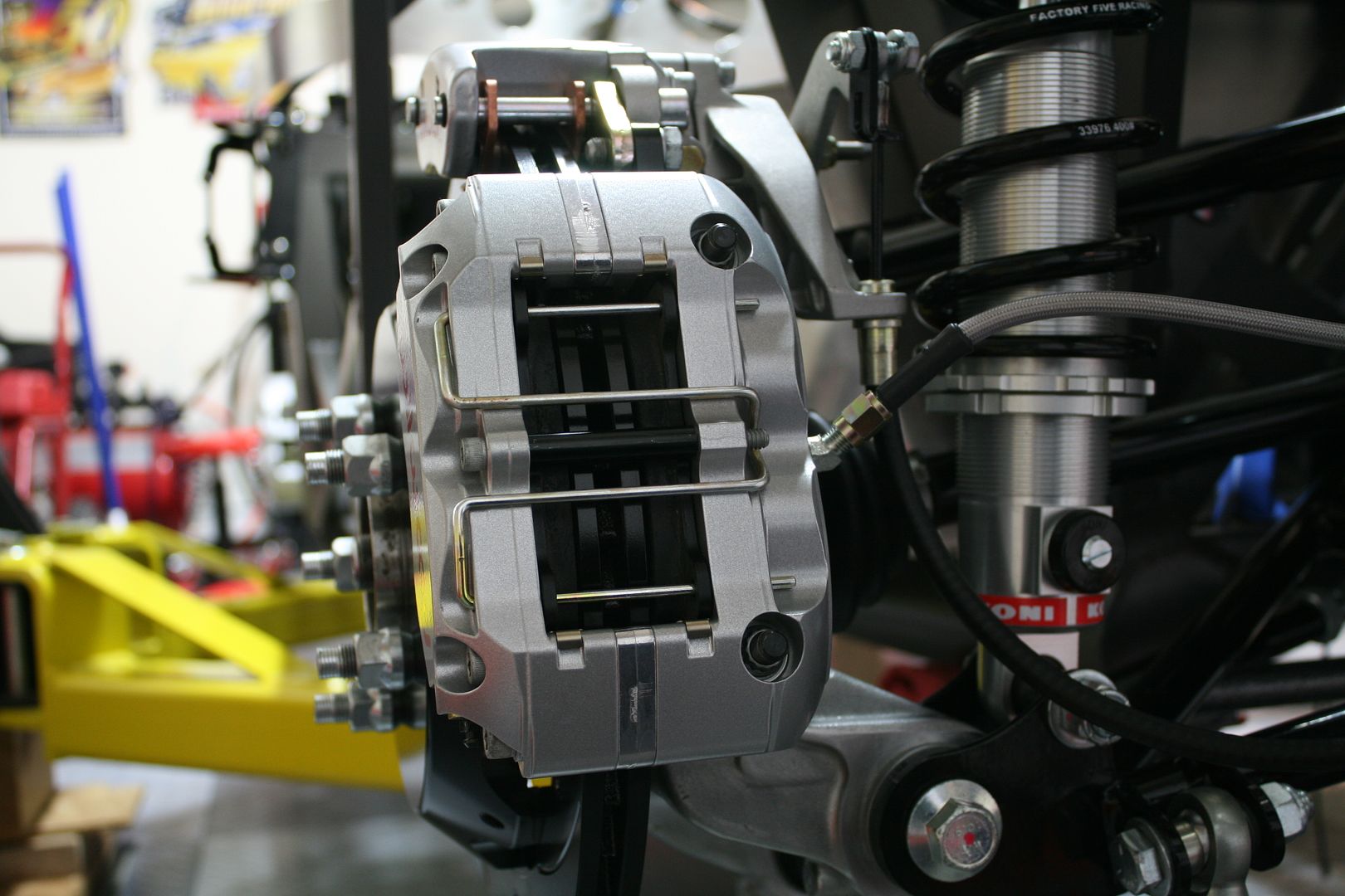
I routed the e-brake cables per the instructions, and looks OK to the rear mounting holes. I’m going to look for alternatives to going under the 4 inch tube to the handle. Still can’t get my head around that, even though I know many do it and it’s fine. The instructions don’t specifically say where to mount the chassis end of the flex hoses, but I could kind of see them in some of the pictures and ended up (I think) in the same locations. This should provide easy enough access to the brake lines.
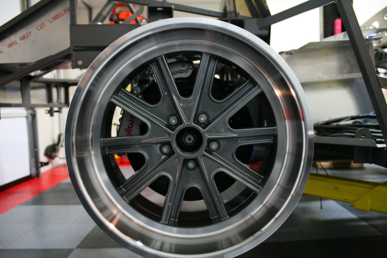
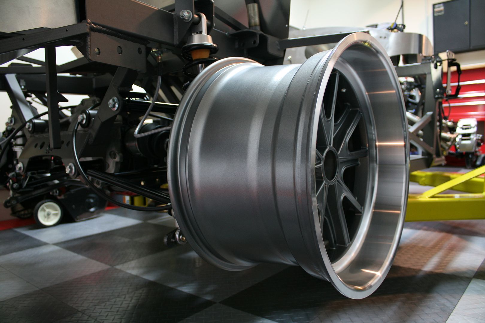
I had to drag out one of the 18 inch rear wheels to check the clearance and also just see what it looked like on there. Clearance all good. They are huge though.
Last edited by edwardb; 12-20-2015 at 06:17 PM.
Build 1: Mk3 Roadster #5125. Sold 11/08/2014.
Build 2: Mk4 Roadster #7750. Sold 04/10/2017.
Build Thread
Build 3: Mk4 Roadster 20th Anniversary #8674. Sold 09/07/2020.
Build Thread and
Video.
Build 4: Gen 3 Type 65 Coupe #59. Gen 3 Coyote. Legal 03/04/2020.
Build Thread and
Video
Build 5: 35 Hot Rod Truck #138. LS3 and 4L65E auto. Rcvd 01/05/2021. Legal 04/20/2023.
Build Thread. Sold 11/9/2023.
-
12-13-2015, 08:56 AM
#145
Senior Member

Update Including Rear Brakes (continued)
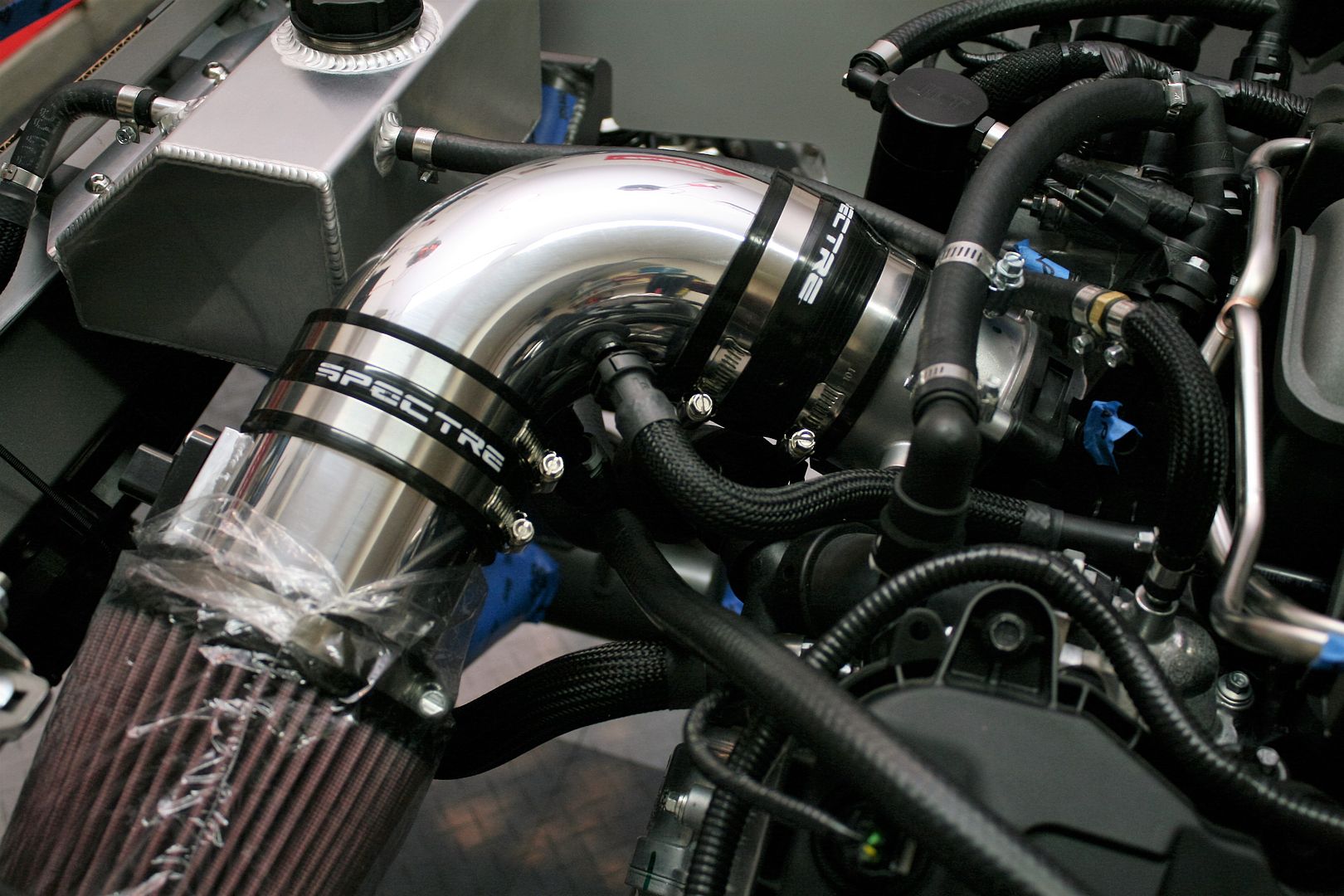
Earlier this week, I pretty much finished up all the cooling lines, vacuum, and PCV hoses on the front of the Coyote. Here you can see the crossover from the inlet to outlet of the heater connections. Ford Racing recommends if not using a heater (I’m not) to connect the two with a 5/16 inch restrictor in the line. I received the Gates quick connects mentioned in my last post and made up the hose. Wasn’t sure what to do for a restrictor. I ended up with a 3/4 inch long steel bushing from the hardware store that I drilled out to 5/16 inch and put in the hose held by the clamp pictured. I also completed the hose from the water neck to the top of the expansion tank. This is the one I mentioned in my last update that wasn’t available anywhere from Ford. Easy enough to make up, except that the water neck connection was 5/16 ID, and the tank 3/8 ID. So searched around and found an adapter and it’s done. I also made up the PCV hose to the bottom of the Spectre intake on the DS, and decided to re-do the PS with the same hose and placing the JLT Performance oil separator a little more neatly.
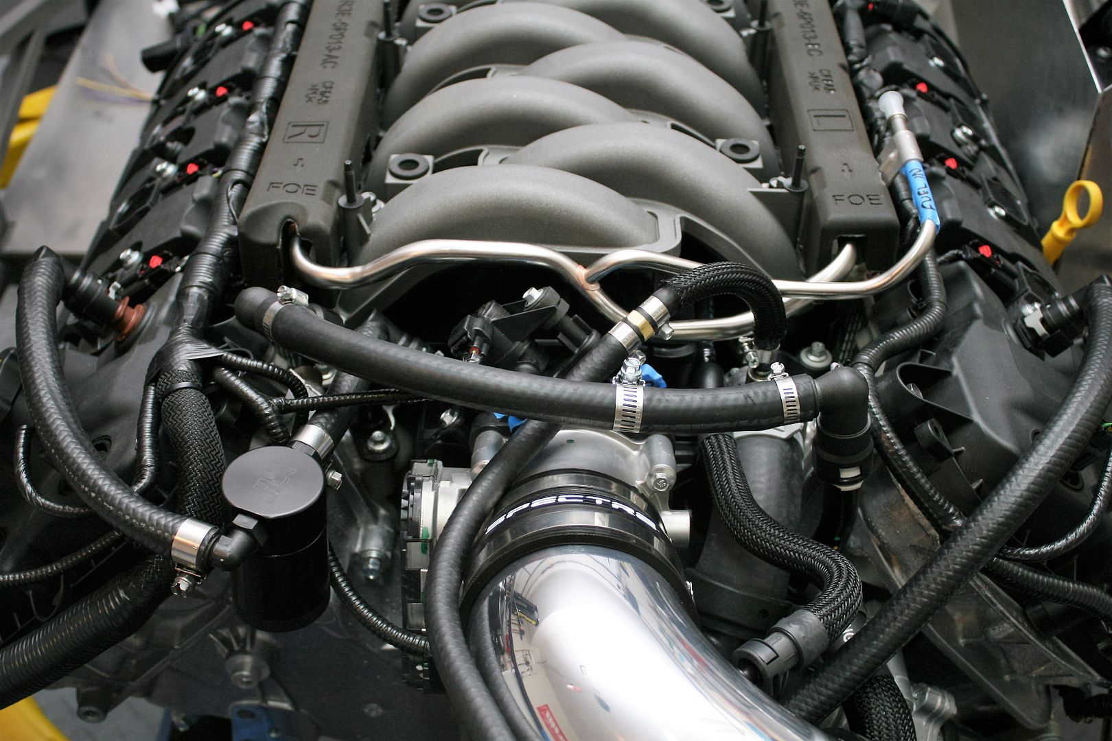
Here you can see the connections I made to the Spectre intake. The top one is for the CMCV system, and the lower one (just visible, sorry) is the DS PCV line. I used connectors from JLT Performance mentioned in some other Coyote build threads. They are aluminum, and fit into a rubber grommet in the intake. I used some Permatex Ultra Black RTV when installing them. Seems to work perfectly. The factory connectors clip right on.
All those hoses and such look pretty messy. No way to make things very pretty. That I can figure out anyway. Looks a little better with the cover in place.
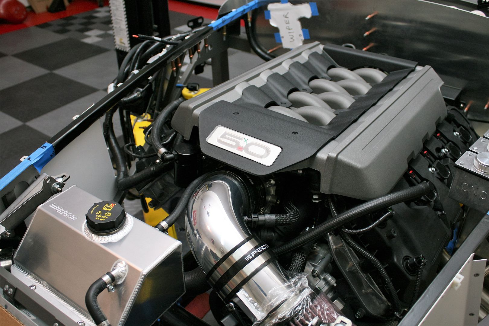
Just a few more details to wrap up on the engine. Mainly power steering and then a final decision about battery location. Then it will be back out so I can finish installing all the aluminum panels. Right now doesn’t appear that I will have any space issues in the front of the engine. But it’s sure busy in there. Onward!
Last edited by edwardb; 12-13-2015 at 09:01 AM.
Build 1: Mk3 Roadster #5125. Sold 11/08/2014.
Build 2: Mk4 Roadster #7750. Sold 04/10/2017.
Build Thread
Build 3: Mk4 Roadster 20th Anniversary #8674. Sold 09/07/2020.
Build Thread and
Video.
Build 4: Gen 3 Type 65 Coupe #59. Gen 3 Coyote. Legal 03/04/2020.
Build Thread and
Video
Build 5: 35 Hot Rod Truck #138. LS3 and 4L65E auto. Rcvd 01/05/2021. Legal 04/20/2023.
Build Thread. Sold 11/9/2023.
-
12-13-2015, 08:30 PM
#146

Originally Posted by
edwardb

.... placing the JLT Performance oil separator a little more neatly.
The JLT oil separator works and accumulates more oil than I expected. With just a little more than 150 miles on mine now, I checked the separator and it had about a quarter cup of oil in it. I recommend this device for anyone running the Coyote engine.
-
12-16-2015, 04:34 PM
#147
Senior Member

Tach Connection
As updates go, this is pretty minor and maybe even a little trivial. But I’ve covered a number of aspects related to the 2015-2016 Coyote installation, and this is one that has to be dealt with. So I'll share what I did. The 2011-2014 Coyote crate motor control pack has a tach connection in the dash harness. Obviously very easy to attach to the tach gauge and away you go. I could not find any mention of a tach connection in the instructions for the 2015-2016 Coyote control pack, so included this in a list of questions when I talked to Ford Racing tech support. The response was (1) No, there isn’t a tach connection in the new control pack, (2) Look at all the other improvements you received (uh…ok…), (3) Recommended using something like an Autometer tach adapter.
I briefly looked at the Autometer piece ($80-90) and didn’t look too bad to wire up. But would have to break into several wires in the Coyote harness. Then I looked at the Speedhut directions for the tach. Good news! One wire to connect and nothing to buy. All that’s needed is a single connection to one of the coil on plug trigger wires, and then calibrate the tach to 1 pulse per 2 revolutions or 1/2 pulse per 1 revolution. In looking at the Coyote wiring to each coil on plug, there are only two wires. One is the same color for all (purple) and the other is a different color for each. According to the Speedhut instructions, this different colored wire is the trigger wire.
So today I decided to add the tach wire. It doesn’t matter which cylinder is selected. I chose #7. I will have other wires running to the gauges on that side (water temp, oil pressure) so this one can join the bundle. Instead of #8 (closest to the firewall) I chose #7 so the end of the connection will still be under the engine cover. After unplugging the connector to the coil on plug and pulling it free to expose the full length, I chose the location where I would break into it. About 3/4 of an inch from where it splits out of the harness to the coil and another branch to the injector. Using a brand new sharp X-Acto blade and a jeweler’s loupe, I carefully cut away about an inch of the tape wrap and then shaved about 3/8 of an inch of insulation from the yellow (in this case) trigger wire. Getting up close like that with a loupe was probably way overkill. But I was determined to not damage anything, nick any wires, whatever. Mission accomplished.
Then I made up the tach connection wire 3-4 inches long using a female spade connector crimped and lightly soldered on one end, and shrink sleeve over the wire and the connector. I wanted a crimped connection to the trigger wire, so cut the crimp end off the right size spade connector and used that to crimp the tach wire onto the exposed trigger wire. I was just able to get a wire crimper in there. Then I put a light touch of solder on the joint, wrapped it back up, and put on a cable tie so the tach wire isn’t pulling on the connection. Only a couple hours work, but now I have a tach connection and I’m satisfied it will work long term and I didn’t do anything to harm the engines wiring harness. BTW, there have been endless threads about whether to solder or not to solder. Let’s not make this one of them. I have a professional quality Weller solder station and have been doing this kind of thing for years. I just put the lightest touch on each connection and apply the heat and solder in such a way that there’s little/no wicking up the wires. I will typically do the same thing with the rest of the chassis wiring with the exception of Weatherpack style connectors. I have a dedicated crimper tool for those connectors and find it makes excellent folded crimps that don’t need additional solder. But I digress. Here are some pics.
Location where I broke into the harness:
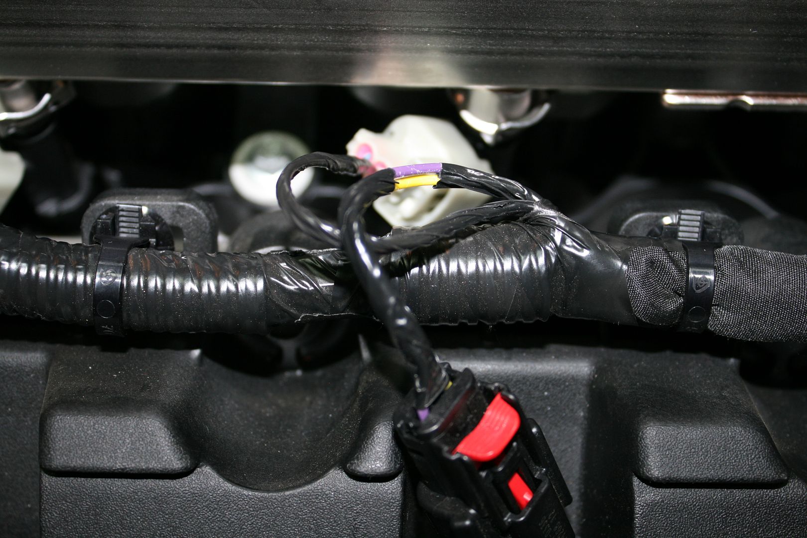
Attachment to the yellow trigger wire. Note all eight cylinders have a purple wire on one side of the connector, the other side is different for each. #7 happens to be yellow:
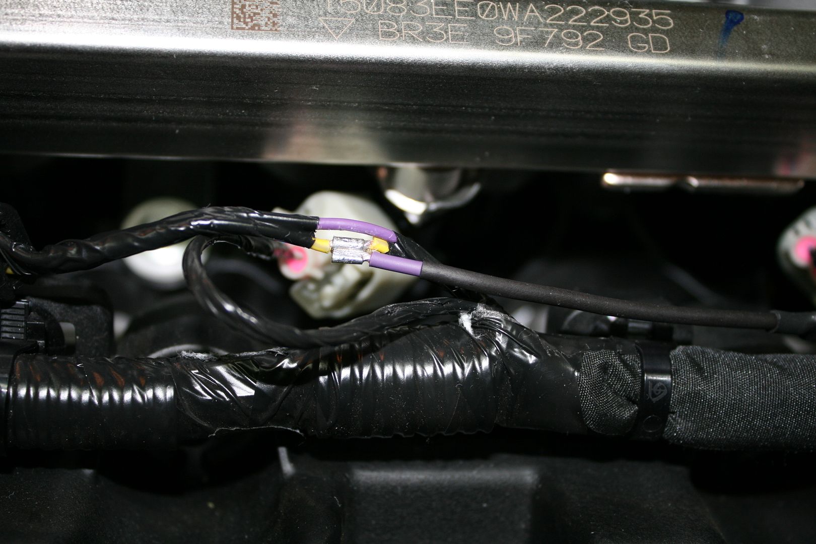
All re-wrapped, in place, and tach wire available for connection to the gauge:
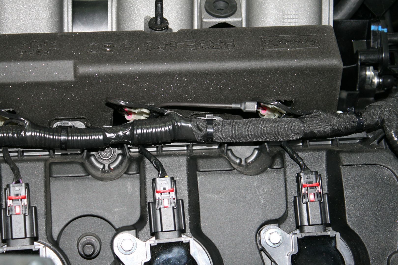
Tomorrow my power steering components are scheduled for delivery, so my next update will be about that. I looked at a number of power steering options, and will share what I chose and why along with the installation.
Last edited by edwardb; 12-16-2015 at 05:19 PM.
Build 1: Mk3 Roadster #5125. Sold 11/08/2014.
Build 2: Mk4 Roadster #7750. Sold 04/10/2017.
Build Thread
Build 3: Mk4 Roadster 20th Anniversary #8674. Sold 09/07/2020.
Build Thread and
Video.
Build 4: Gen 3 Type 65 Coupe #59. Gen 3 Coyote. Legal 03/04/2020.
Build Thread and
Video
Build 5: 35 Hot Rod Truck #138. LS3 and 4L65E auto. Rcvd 01/05/2021. Legal 04/20/2023.
Build Thread. Sold 11/9/2023.
-
12-23-2015, 02:45 PM
#148
Senior Member

Hey Edwardb, With the year coming to a close I'd just like to thank you again for all your detailed posts. It's certainly been a huge help as a first time builder, so thanks again. While not as quick as i'd like I'm making a little progress, Breeze PS rack is in, took a little muscling but done, RT rear trunk box done, front brakes installed last weekend, still waiting on my rear sway bar mounts from the PC, but will hopefully finish up the IRS next. I'm all up to date with parts except for the door latches...maybe I'll get them on the 25th! Wishing all you guys Merry Christmas, Happy Holidays and all the best for 2016, good luck with the builds! Cheers
-
12-23-2015, 03:20 PM
#149
Member

I second Paul's comments, not only on this build but your previous projects as well. Many thanks to you and all of the more experienced builders that share their time with those of us that are new to this. Merry Christmas and Happy New Year!
Doug
Mk4 Roadster #8567, IRS, Levy Racing 427w Stroker, 8-stack EFI
-
Post Thanks / Like - 0 Thanks, 1 Likes
-
12-23-2015, 05:11 PM
#150
Senior Member

Thanks guys! I'm enjoying sharing this build. It's very cool that it has several new aspects, and especially enjoyable knowing that others are following during their first builds. Merry Christmas and Happy New Year to all.
Build 1: Mk3 Roadster #5125. Sold 11/08/2014.
Build 2: Mk4 Roadster #7750. Sold 04/10/2017.
Build Thread
Build 3: Mk4 Roadster 20th Anniversary #8674. Sold 09/07/2020.
Build Thread and
Video.
Build 4: Gen 3 Type 65 Coupe #59. Gen 3 Coyote. Legal 03/04/2020.
Build Thread and
Video
Build 5: 35 Hot Rod Truck #138. LS3 and 4L65E auto. Rcvd 01/05/2021. Legal 04/20/2023.
Build Thread. Sold 11/9/2023.
-
01-03-2016, 12:12 AM
#151
Senior Member

Power Steering
It’s been a little while since my last update. Family visits and travel during the holidays will do that. All good, and a little bit of a break was good. Also my usual waiting for parts. The first time, and then the do-overs. I’m sure that doesn’t happen to anyone else. Tonight I finished the mock-up of the power steering installation. It will all come back out when I take the engine out in the next week or two. But it should go back in for good very quickly when the time comes.
First a few words about power steering. For me it’s not a complicated discussion. My first build didn’t have power steering. It was my single regret from the build. My second did, and what a difference. Yes it’s about effort, mainly at slower speeds and parking. But it also allows significantly more caster in the front end alignment (from around +4 to +8) which gives the car better straight line tracking and high speed stability. It just makes the car such a pleasure to drive. For a Coyote build, it does get a little interesting though. Ford doesn’t install engine driven power steering in any of their cars using the Coyote. Like more and more modern cars, they are using electric power steering. So any engine driven setup for the Coyote will come from the aftermarket.
I won’t get real deep into the options, but there are several that I looked at. All go on the passenger side of the engine. Ford Racing sells an adjustable bracket that mounts near the bottom, and then uses a mod motor stock pump. This is the setup Factory Five has on the prototype Anniversary Roadster. It’s not cheap though. The bracket alone is around $250. Some guys have reported interference problems with the pulley and the frame. Another choice is a homemade bracket instead of the Ford Racing one, and then again a mod motor stock pump. Another forum member sent me the pattern, and it wouldn’t be hard to make. The other two choices place the pump more in the center of the passenger side. Eliminates the possible frame interference issue, but this is also the Ford location for the A/C compressor. So if A/C is in your build plan, these won’t work for you. One is sold by Forte. Looks good, but also isn’t cheap and again uses a stock mod motor pump. Another choice, and the one I chose, is a setup from KRC Power Steering. Again, certainly not cheap. I guess that’s a common theme for any of the choices when you add everything up. But for me there were several advantages that swayed me to KRC. First it’s an aftermarket pump that seems very high quality. It comes with AN fittings as standard. If you want to use AN hoses (I did) it completely eliminates fumbling around with the various adapters, O-rings, etc. With the provided pulleys it runs the proper RPM. One of the biggest advantages IMO is that has a provision for changeable flow valves. This allows you to tailor the amount of boost. They’re easy to change, although not as easy as twisting the knob on a Heidts valve. But for my driving I don’t need that. Several other forum Coyote builds have been with the KRC setup, which I have studied carefully. Thanks guys! All report excellent results.
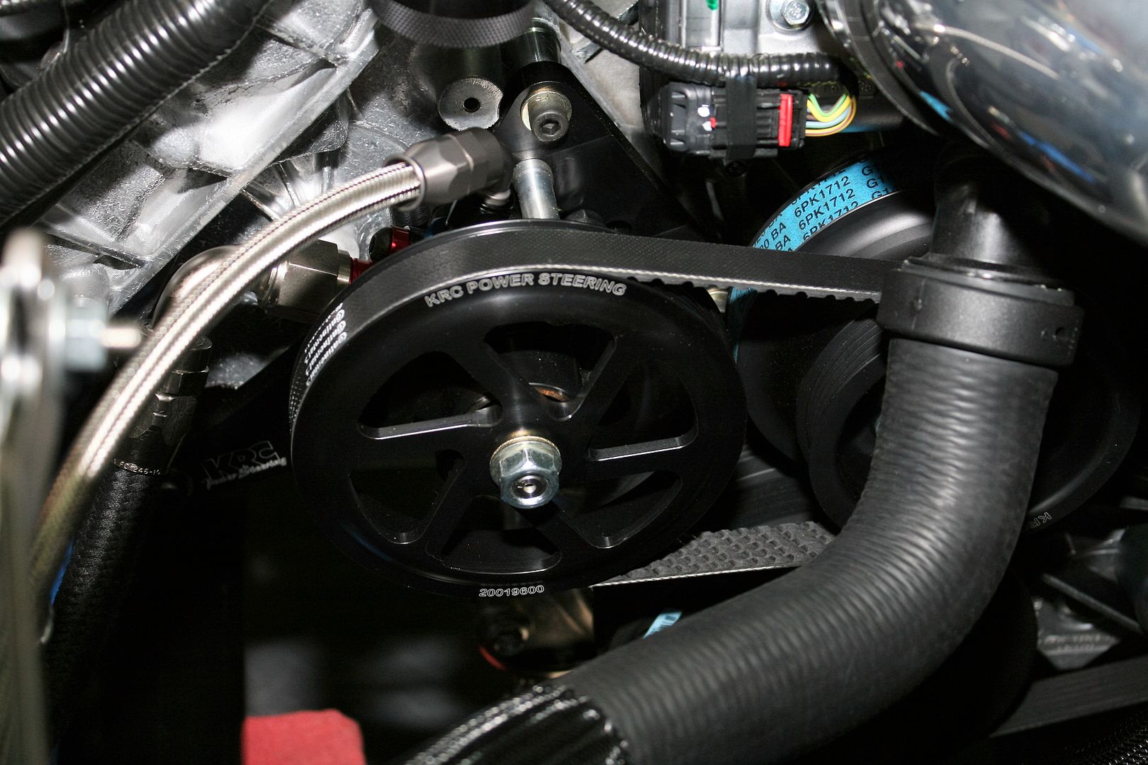
Mid-December I placed my order for the KRC components directly with KRC. I received everything in just a couple of days. The KRC setup includes a new water pump pulley with a second pulley for the power steering drive. I mounted everything up, and unfortunately immediately noted a problem. The power steering pump and the drive pulley on the water pump were over 1/2 inch misaligned. I’ll spare you the long version of the story and just give this hint: Buy the complete setup under part number 66302050. Don’t do what I did and buy the cast iron pump and engine mounting kit separately. If you do, you will get the wrong power steering pump pulley. After a couple calls to KRC, we figured out the problem, they shipped the right pulley, I returned the wrong one, and all was OK. It was all a little bit harder than it had to be though, and I’ll leave it at that. Buy the complete setup and you’ll be OK. Another hint. KRC is sold through various other outlets. I see the setup listed at Summit, Jegs, Pegasus, etc. And it seems to be a bit cheaper. Still apparently shipped directly from KRC.
OK, enough about that. On to the installation. Here’s all the pieces you get. The blue colored piece right in the middle of the picture is the flow control valve. Based on forum recommendations for the cast iron pump, I chose the #4 valve, which is flow rated at 1.66 GPM. The valve is mounted in the top of the pump, and has the -6 AN threads for the high pressure pump output. To change the valve, disconnect the hose, remove the valve, install the new valve, replace the hose. It's that simple.
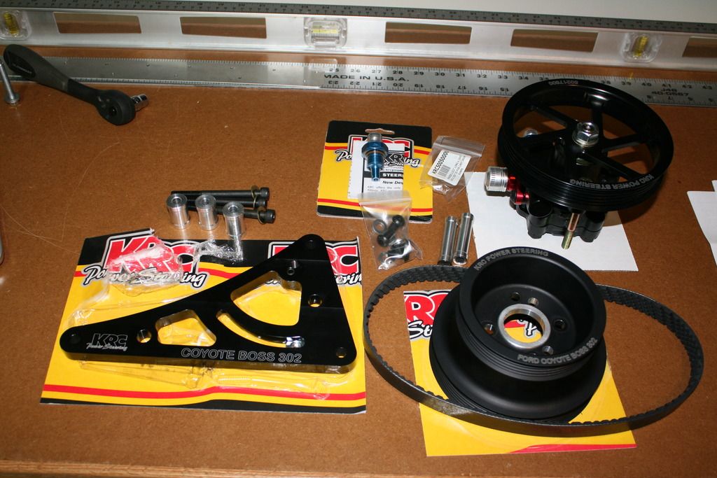
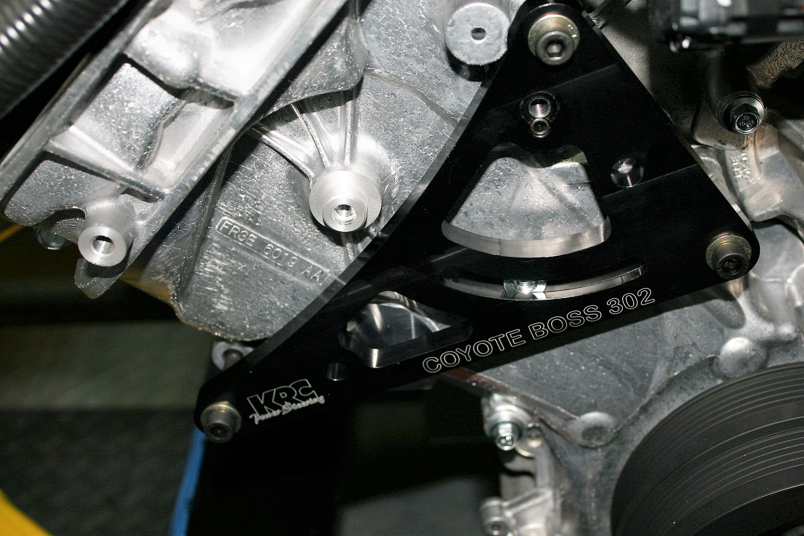
The pump bracket is held in place by three bolts, supplied with the bracket. They replace these front cover bolts on the Coyote, marked with blue tape for the picture:
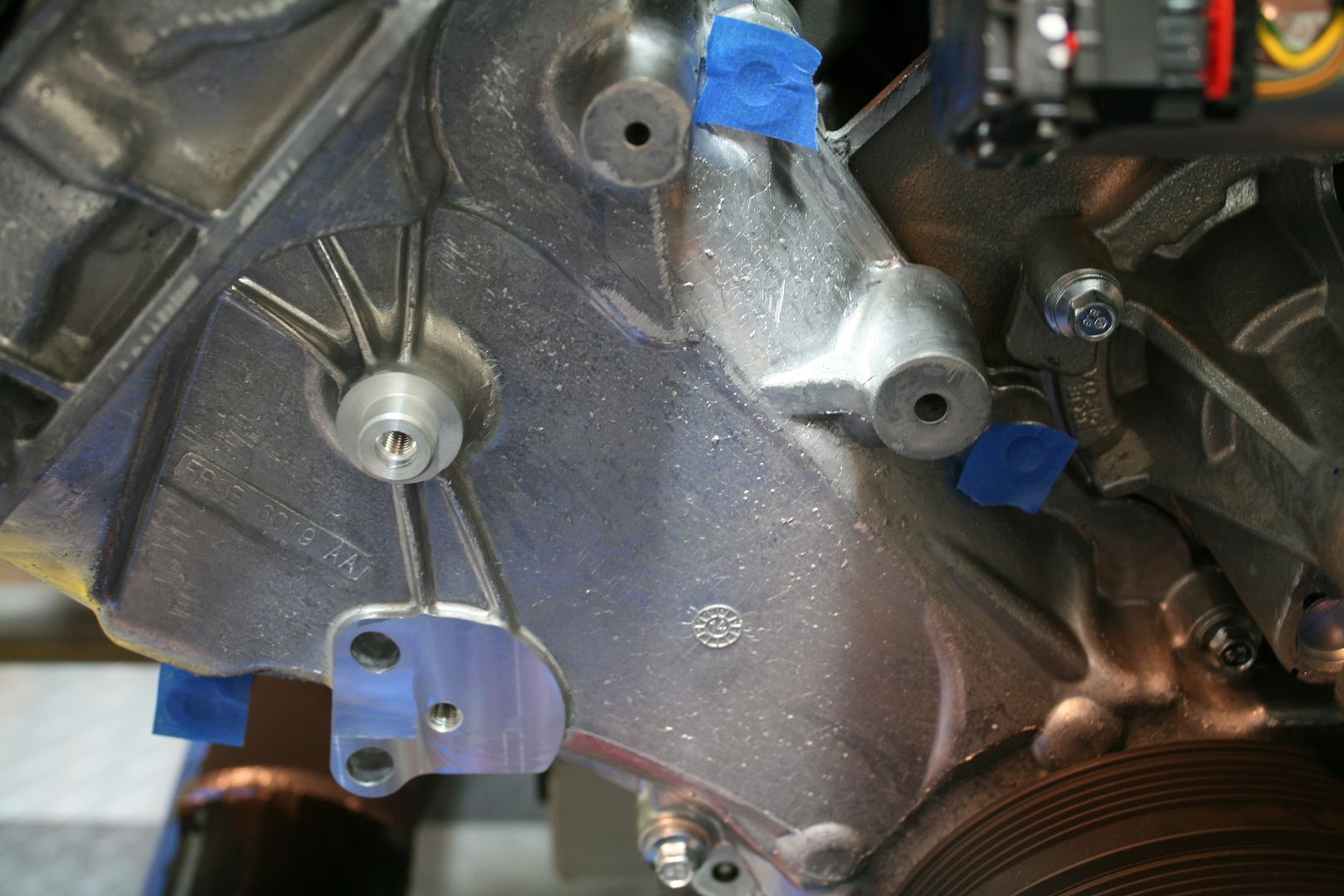
This is the pump bracket on the front of the engine. There are spacers between the bracket and the engine. I hadn't installed them yet when this picture was taken:
And with the pump, new water pump pulley, and serpentine belt installed:
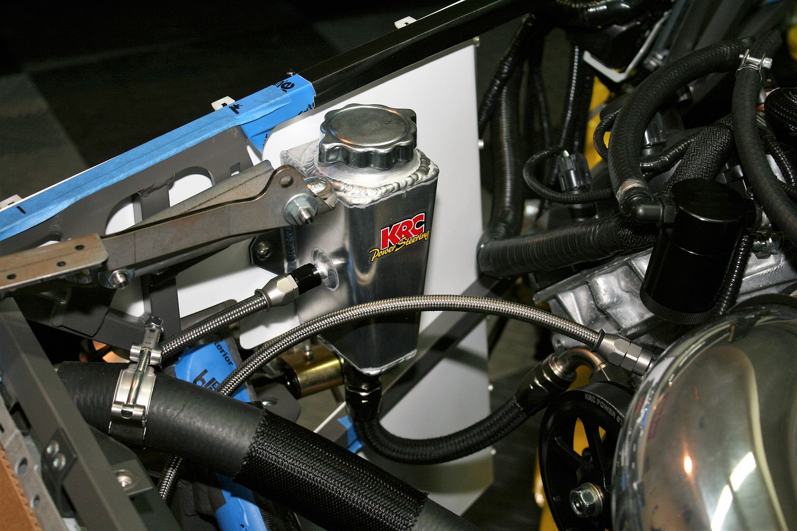
I looked at a number of options, and decided on the KRC 91515000 reservoir. It’s a nice piece with an internal baffle. Many of the reservoirs out there aren’t baffled. I settled on this location on the F panel. It’s a little tight to the engine and pump, but works out OK and keeps the overall plumbing layout relatively simple. The instructions from KRC say that the top of the fluid inside the reservoir must be at least two inches above the top of the pump. I easily meet that requirement. The bottom of the tank is just slightly below the top of the pump. My biggest concern was the relatively tight bend for the return hose from the bottom of the tank to the pump. I tried a number of -10 AN fittings and ended up with a straight and right angle. Regular -10 AN braided stainless was way too stiff to make this bend. So I tried the Aeroquip StartLite Aramid hose, which has the same liner as braided stainless but is much more flexible. I think it’s going to be OK.
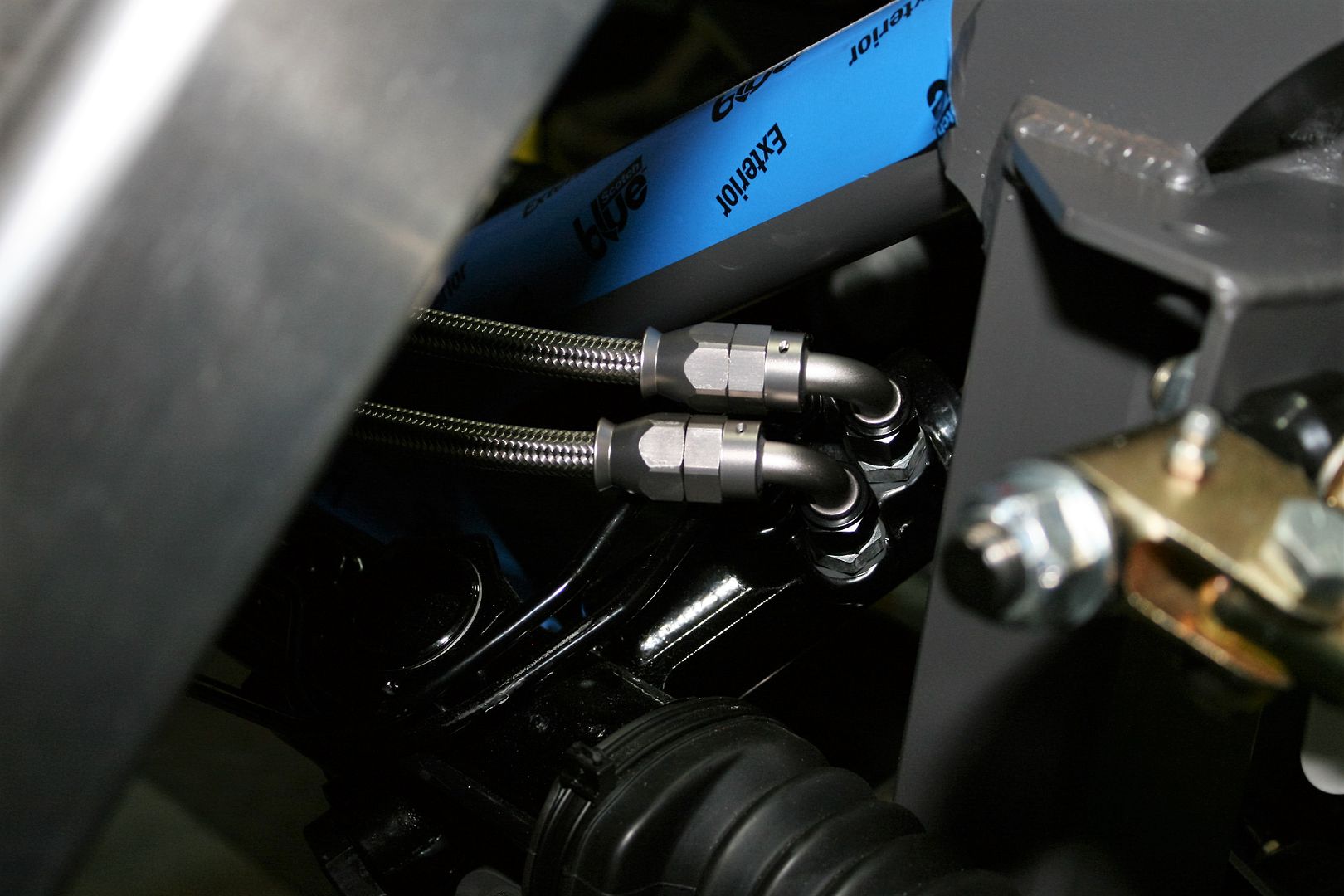
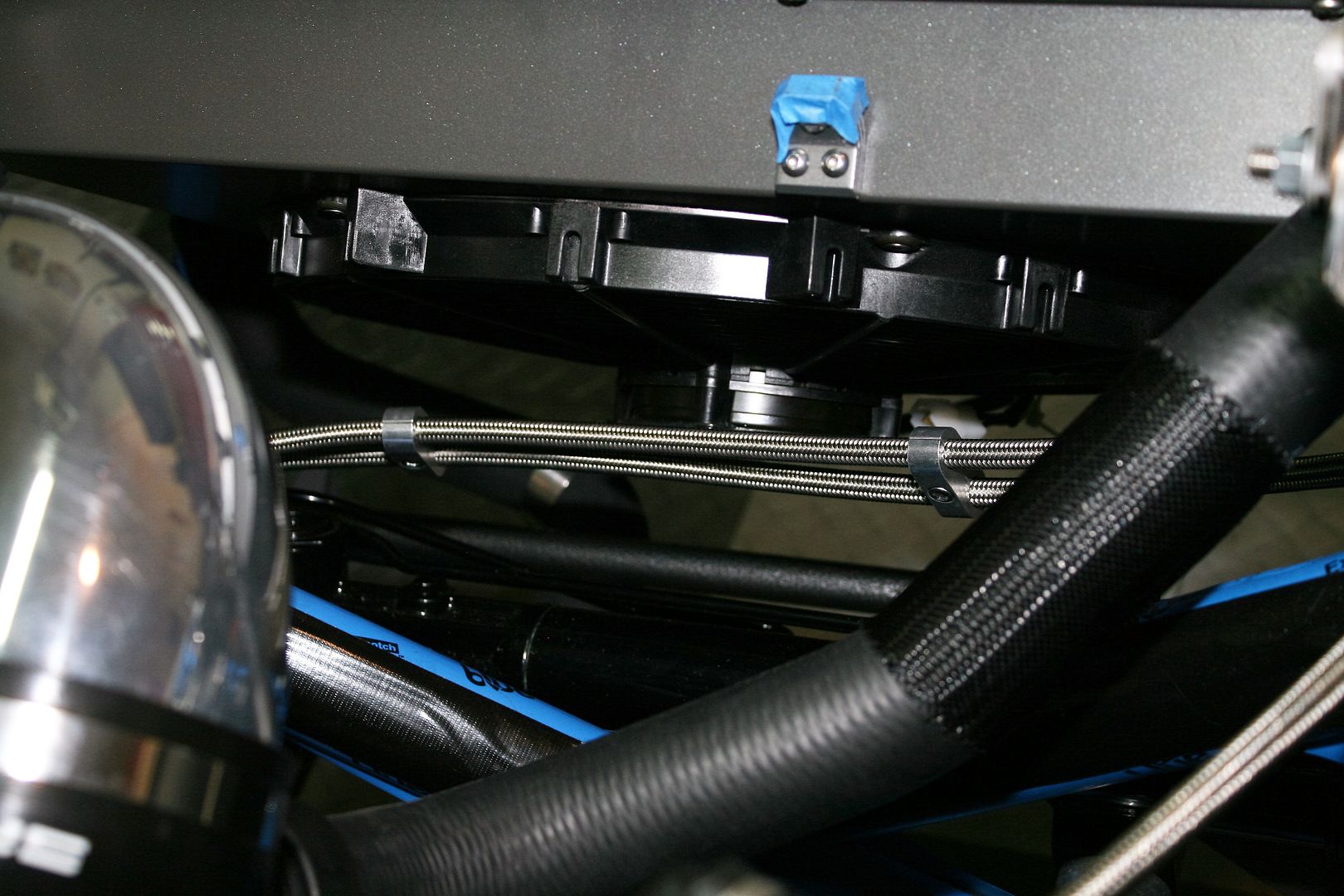
For all the high pressure hose, I used braided stainless Teflon lined hose and fittings from Mark at Breeze Automotive. I bought exactly what I needed, and managed to ruin one of the hoses trying to re-use one of the little ferrules contained in these kind of connectors. I’m not even going to try to explain what I did, but it was a learning experience. Another quick order to Breeze and I was good to go. Here are the lines coming out of the PS rack:
Crossing behind the radiator and cooling fan:
Last edited by edwardb; 01-03-2016 at 03:29 PM.
Build 1: Mk3 Roadster #5125. Sold 11/08/2014.
Build 2: Mk4 Roadster #7750. Sold 04/10/2017.
Build Thread
Build 3: Mk4 Roadster 20th Anniversary #8674. Sold 09/07/2020.
Build Thread and
Video.
Build 4: Gen 3 Type 65 Coupe #59. Gen 3 Coyote. Legal 03/04/2020.
Build Thread and
Video
Build 5: 35 Hot Rod Truck #138. LS3 and 4L65E auto. Rcvd 01/05/2021. Legal 04/20/2023.
Build Thread. Sold 11/9/2023.
-
01-03-2016, 12:13 AM
#152
Senior Member

Power Steering (continued)
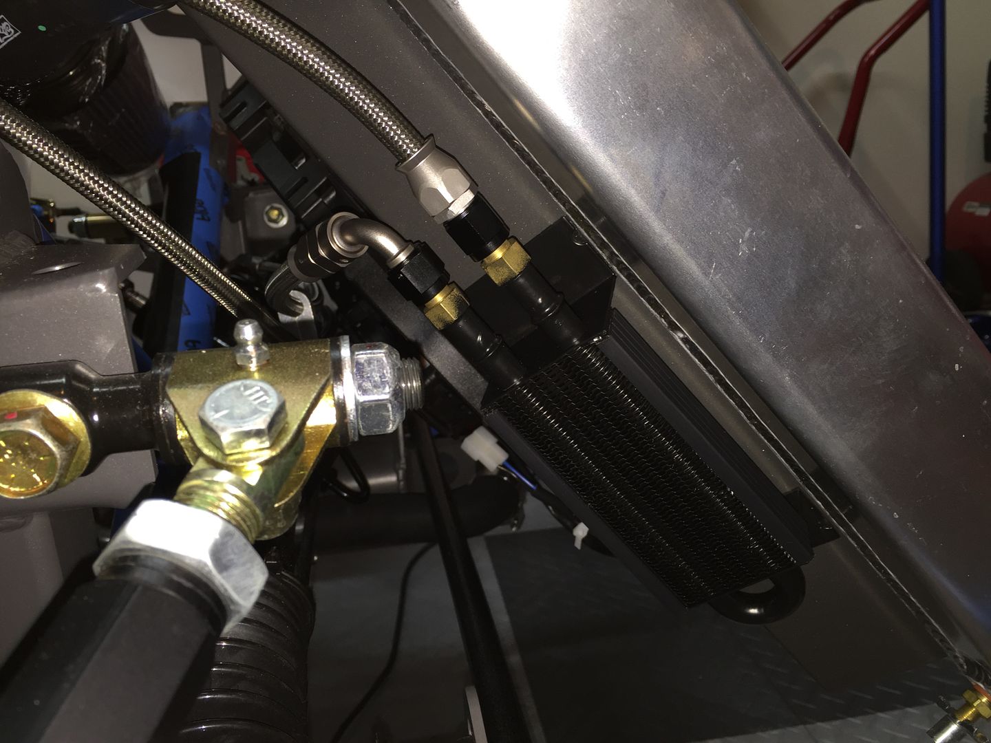
I included a small cooler on the return line to the reservoir. I mounted it on the passenger side of the radiator cooling shroud. I don’t know if it’s really needed, but much easier to do now than later. I used the same exact Derale 13310 on my last build.
That’s about it for the power steering. While waiting for parts, I’ve continued to make progress drilling panels and getting them ready for powder coat. I have all the trunk pieces done, and starting on the cockpit. I’ve decided I have room for the front mounted battery, so will be ordering that kit from Breeze next. Just a few more details and a lot of note taking, and the engine will come back out so I can finalize all the sheet metal and power wiring. I've been working on my fuel and brake line material list and layout. Getting close I think. Yesterday I checked the FF stock e-brake handle and the provided Wilwood cables. Looks like it's going to work OK, but I still just can't get used to routing the cables under the 4 inch chassis tube. I've managed to avoid that on my other builds. May not be so lucky this time. One thing I noticed was that the separate Wilwood e-brake calipers require very little cable movement to actuate.
Last edited by edwardb; 01-03-2016 at 12:37 AM.
Build 1: Mk3 Roadster #5125. Sold 11/08/2014.
Build 2: Mk4 Roadster #7750. Sold 04/10/2017.
Build Thread
Build 3: Mk4 Roadster 20th Anniversary #8674. Sold 09/07/2020.
Build Thread and
Video.
Build 4: Gen 3 Type 65 Coupe #59. Gen 3 Coyote. Legal 03/04/2020.
Build Thread and
Video
Build 5: 35 Hot Rod Truck #138. LS3 and 4L65E auto. Rcvd 01/05/2021. Legal 04/20/2023.
Build Thread. Sold 11/9/2023.
-
01-03-2016, 01:30 AM
#153
Looks very well designed, as per usual. Did you decide to attach the reservoir directly to the F panel with bolts, rivets, or is there some sort of a bracket hidden behind the reservoir? Based upon your usual detailed explanation, it appears to be attached directly. Is there any concern that the thin aluminum F panel may not be strong enough to support this piece and the ongoing vibration it will receive? As always, thank you for your detailed descriptions and photos.
-
01-03-2016, 05:28 AM
#154
Carl

EdwardB,
The KRC power system setup looks great. I really like the valve adjustment to change boost.
"Yesterday I checked the FF stock e-brake handle and the provided Wilwood cables. Looks like it's going to work OK, but I still just can't get used to routing the cables under the 4 inch chassis tube. I've managed to avoid that on my other builds. May not be so lucky this time."
I did not like the setup that puts the cables running under the 4 inch chassis tube and solved it by using a Lokar cable kit with a modified FFR e-brake mechanism.
Here is the drawing showing the difference between the supplied lever and the one I made.

In addition to the Lokar cables, I used the following Lokar parts ...

Here is the final assembly ... the bottom of the extended lever does not drop below the 4" round tube.

Carl
Mk 4 Roadster
October 25, 2012 - Kit Arrives
April 8, 2013 - Build Starts
August 23, 2015 - Rolling Chassis/Engine & Transmission Installed
March 26, 2016 - Go Cart
-
01-03-2016, 07:32 AM
#155
Senior Member


Originally Posted by
Jazzman

Looks very well designed, as per usual. Did you decide to attach the reservoir directly to the F panel with bolts, rivets, or is there some sort of a bracket hidden behind the reservoir? Based upon your usual detailed explanation, it appears to be attached directly. Is there any concern that the thin aluminum F panel may not be strong enough to support this piece and the ongoing vibration it will receive? As always, thank you for your detailed descriptions and photos.
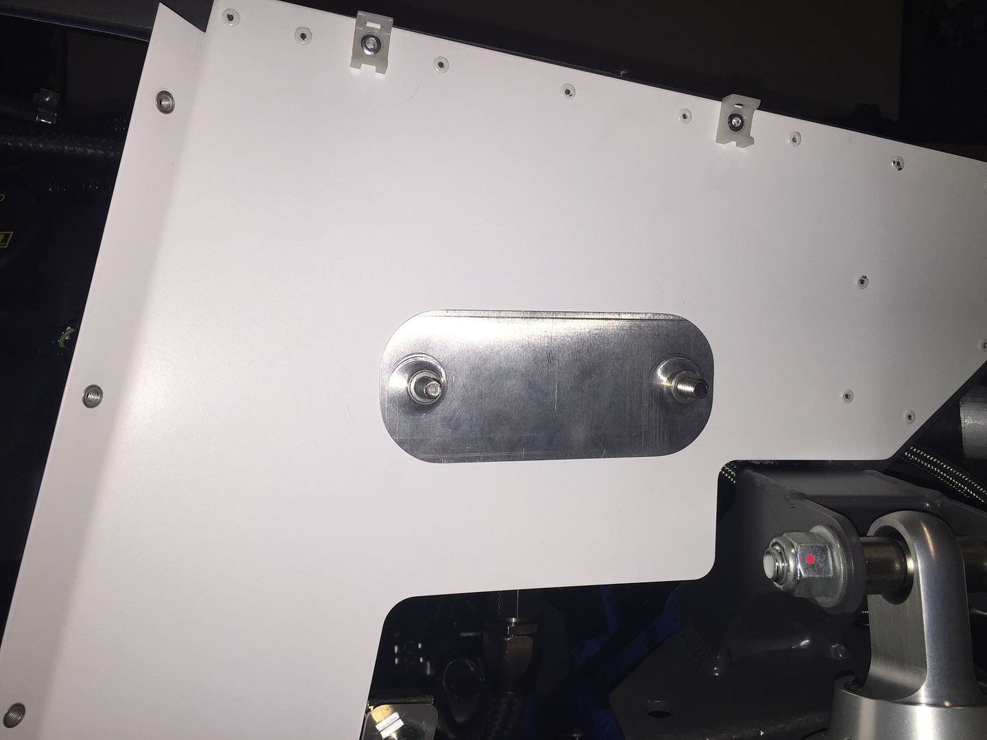
The reservoir is attached to the F panel with bolts through mounting ears on the sides of the tank. You can just see the front one on the picture I posted. The F panel is plenty strong for the reservoir. On my other Mk4, I bolted the PS reservoir on one F panel, and the radiator overflow tank on the other. Zero issues. The one thing I did do on this build though was to use rivnuts so I could install/remove the reservoir without having to chase nuts and washers inside the wheel well. Rather than putting them directly in the F panel, I made a backing plate and installed them there. This is also maybe a little more rigid since it doubles the aluminum. I will have it powder coated white to match the F panel (gotta keep those inner wheel wells neat and clean  ) and then stick in place with some adhesive. The 5/16 inch nutserts are way overkill, but what I had on hand. Plus matches the hardware on the radiator expansion tank. I also need to find some shorter bolts or trim the ones I used. Snapped a quick pic this morning:
Last edited by edwardb; 01-03-2016 at 07:44 AM.
Build 1: Mk3 Roadster #5125. Sold 11/08/2014.
Build 2: Mk4 Roadster #7750. Sold 04/10/2017.
Build Thread
Build 3: Mk4 Roadster 20th Anniversary #8674. Sold 09/07/2020.
Build Thread and
Video.
Build 4: Gen 3 Type 65 Coupe #59. Gen 3 Coyote. Legal 03/04/2020.
Build Thread and
Video
Build 5: 35 Hot Rod Truck #138. LS3 and 4L65E auto. Rcvd 01/05/2021. Legal 04/20/2023.
Build Thread. Sold 11/9/2023.
-
01-03-2016, 07:40 AM
#156
Senior Member


Originally Posted by
carlewms

I did not like the setup that puts the cables running under the 4 inch chassis tube and solved it by using a Lokar cable kit with a modified FFR e-brake mechanism. Carl
Thanks for positing those to my build thread. I actually found your pics and write-up while searching and looking at what others have done. I saved and printed the pictures and is one of the solutions I'm going to look at. It's a very nice and well executed solution. I'm just not sure how the extended lever, meaning the handle will need to move less, will work with the Wilwood e-brake calipers that require so little actual cable movement. But this is the first thing I'm going to try. I will mock it up somehow and see how it works. I think I could use the existing cables and hardware. They would just have to be shortened a little. We'll see. Thanks again.
Last edited by edwardb; 01-12-2016 at 01:00 AM.
Build 1: Mk3 Roadster #5125. Sold 11/08/2014.
Build 2: Mk4 Roadster #7750. Sold 04/10/2017.
Build Thread
Build 3: Mk4 Roadster 20th Anniversary #8674. Sold 09/07/2020.
Build Thread and
Video.
Build 4: Gen 3 Type 65 Coupe #59. Gen 3 Coyote. Legal 03/04/2020.
Build Thread and
Video
Build 5: 35 Hot Rod Truck #138. LS3 and 4L65E auto. Rcvd 01/05/2021. Legal 04/20/2023.
Build Thread. Sold 11/9/2023.
-
01-05-2016, 05:01 PM
#157
Senior Member

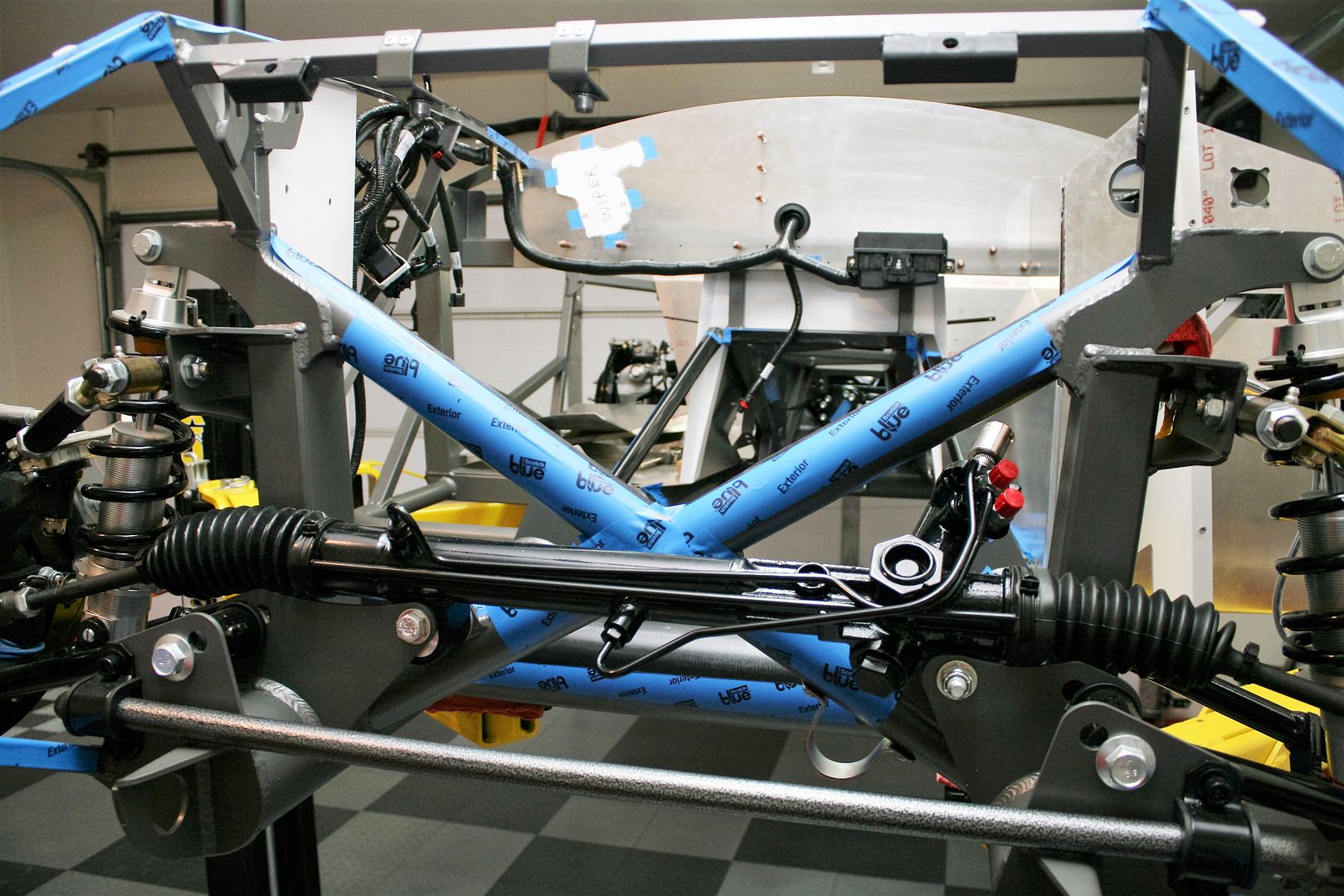
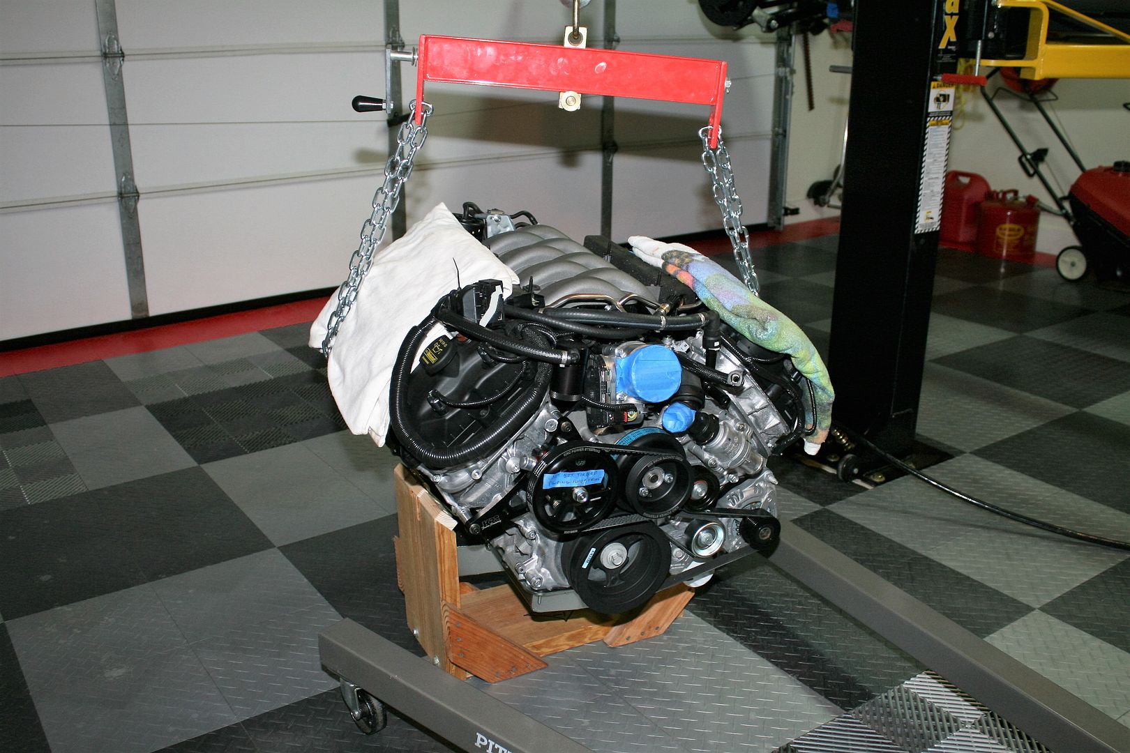
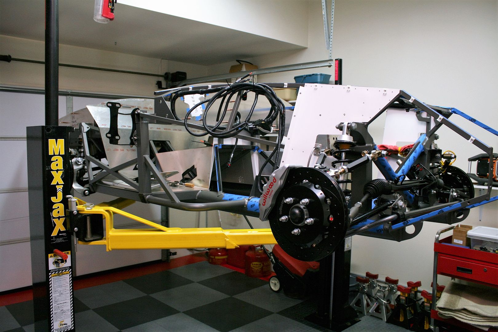
Coyote Has Left the Building
As updates go, this is about as trivial as it gets. But still represents a pretty big milestone. Yesterday I disassembled much of what I’ve been working on the past weeks, took a lot of pictures, took a number of measurements, and made a few pages of notes. Then today we (my trusty wife and I) took the Coyote back out of the chassis. It’s not hard without most of the sheet metal and the trans, but still a tight fit. Had a bit of a setback when I unfolded my couple year old Harbor Freight 2-ton shop crane and it didn’t work. No pressure on the handle when pumping and no movement. I figured a major malfunction, but a quick Google search and found the solution. Needed the “valves flushed.” There was a specific sequence of opening and closing the valve and manually moving the lift arm, and it was good to go. Is this anything like exercising the muffler bearings? Now onward with finishing the sheet metal and getting powder coated and installed, putting in the power wiring, brake lines, fuel lines, and spraying some Lizard Skin. Then the Coyote with the TKO this time will go back in hopefully for the last time. I'm expecting in a few months.
4 degrees here this morning. My heated garage stayed warm enough, but I'm sure jealous of you guys out there in warm climates that are driving right now. Oh well, some pics:
Empty engine bay:
Coyote out. I’ll tuck in the corner of the garage for a bit.
Nice to have the lift back in play again. I couldn’t use it while I had the engine propped in place. Man I got spoiled fast with that thing.
Collection of stuff removed and now in the basement. I expect to go back in very quickly the next time:
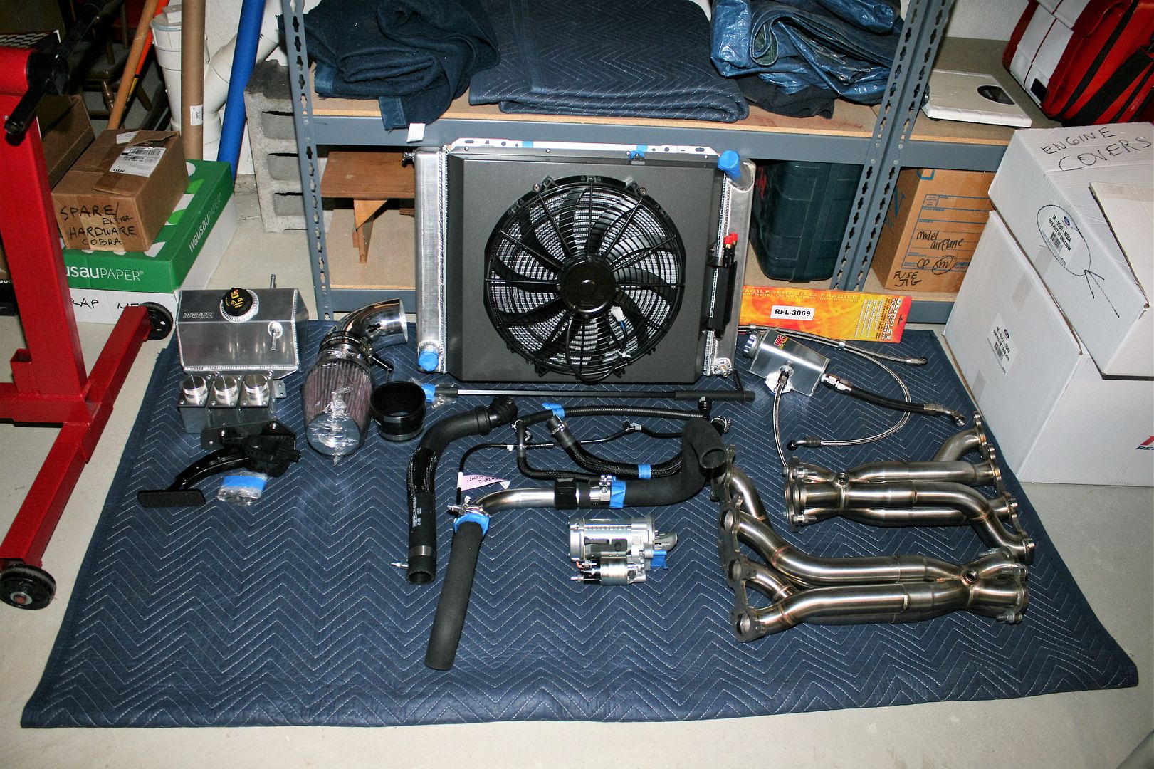
Last edited by edwardb; 01-05-2016 at 05:14 PM.
Build 1: Mk3 Roadster #5125. Sold 11/08/2014.
Build 2: Mk4 Roadster #7750. Sold 04/10/2017.
Build Thread
Build 3: Mk4 Roadster 20th Anniversary #8674. Sold 09/07/2020.
Build Thread and
Video.
Build 4: Gen 3 Type 65 Coupe #59. Gen 3 Coyote. Legal 03/04/2020.
Build Thread and
Video
Build 5: 35 Hot Rod Truck #138. LS3 and 4L65E auto. Rcvd 01/05/2021. Legal 04/20/2023.
Build Thread. Sold 11/9/2023.
-
01-05-2016, 05:39 PM
#158
-
01-05-2016, 07:39 PM
#159
Senior Member

You ain't lying about the cold weather. It was 64 degrees today in Apollo Beach, FL. I almost broke out a long-sleeve t-shirt.
I'm interested in your two-post lift. Can you share where you purchased it, and a part number? I'm looking to get one for my garage. How do you like yours?
Carlos
FFR Coupe #0635; Ford 347ci, Tremec TKO500, 8.8 rear end w/ 3.27:1 gears, Cobra/SVO brakes
-
01-05-2016, 10:03 PM
#160
Senior Member


Originally Posted by
Jazzman

You're right, it sure is cold today! It got down to 55 in the shop yesterday before I turned on my little space heater! Sunday when I worked in the shop I had to give up my standard shorts and t-shirt for long pants and a short sleeve t-shirt because it dropped to 65 with the garage door open and the sun shining!!

Of course you will be the one laughing in July when it is 115 here in the shade.
Glad the engine came out so smoothly. Aren't wives wonderful! Mine steps in and helps when I need a second pair of hands too.
Why did you decide to remove the radiator? Since it is in front of the X frame and the steering rack, did it somehow restrict the engine from coming out? Or was it necessary to remove the radiator in order to get the shop crane close enough to lift the engine safely?
I notice you have a hole cut in the firewall to route cable through. Why did you choose this location as opposed to using the already provided hole on the PS of the firewall? What size hole did you cut and did you use some sort of rubber grommet to protect the cables? Do you plan to try to seal the hole to prevent heat from entering the cockpit? (Oh that's right, it was 4 degrees there yesterday! You aren't concerned with heat coming in, only heat going out!!

At the rate you are going, you will be ready to unveil this work of art at Huntington Beach in April!

Originally Posted by
Carlos C

You ain't lying about the cold weather. It was 64 degrees today in Apollo Beach, FL. I almost broke out a long-sleeve t-shirt.
I'm interested in your two-post lift. Can you share where you purchased it, and a part number? I'm looking to get one for my garage. How do you like yours?
Carlos
Alright you guys, you're supposed to feel sorry for us freezing up here in the frigid north. Not give me a hard time and complain about maybe putting on a sweater. I'll remember that come summer time where we're out cruising all day in the beautiful 70-80 degree Michigan weather and you can't go out after 9:00 AM. 
OK, on to more productive things. The radiator does need to be out of the way in order for the shop crane to reach if you're loading the engine from the front. That's with the 2-ton I have out to the longest setting. It's possible to load in from the side, and some guys do that. And with the body on it's pretty much the only choice. But I strongly prefer doing it this way if I can. With the body off, I think it's the most common method. The wiring and power distribution box in that picture is the Coyote controls pack wiring. I don't remember the exact size of the hole, but it fits the grommet included with the Coyote harness. That's pretty much the only location for everything to work. I'll caulk it up good when it's permanently installed, and I'm not expecting any heat issues from it. If you're not using a Coyote, ignore that stuff. For the Ron Francis harness, the front harness comes through the top of the driver's side footbox, and the rear harness at the top side of the driver's footbox. You typically need a couple of small holes in the firewall for the gauge senders, choke, power wires, etc. But nothing like that big hole. The 2-post life it a Danmar MaxJax. http://www.maxjaxusa.com/. It's pretty basic, but fits my garage perfectly. I'm happy with it, and the difference in comfort and convenience while working on the car is amazing. My body just wasn't going to take another build crawling on the ground and rolling on my back using jackstands. They're available all over the place. Google it. When I was shopping the best price I found was Costco, so that's where I got it. I've had it for about 1-1/2 years now.
Last edited by edwardb; 01-06-2016 at 07:11 AM.
Build 1: Mk3 Roadster #5125. Sold 11/08/2014.
Build 2: Mk4 Roadster #7750. Sold 04/10/2017.
Build Thread
Build 3: Mk4 Roadster 20th Anniversary #8674. Sold 09/07/2020.
Build Thread and
Video.
Build 4: Gen 3 Type 65 Coupe #59. Gen 3 Coyote. Legal 03/04/2020.
Build Thread and
Video
Build 5: 35 Hot Rod Truck #138. LS3 and 4L65E auto. Rcvd 01/05/2021. Legal 04/20/2023.
Build Thread. Sold 11/9/2023.


 Thanks:
  Likes:


 Reply With Quote


