FormaCars

Visit our community sponsor

Thanks Thanks:  0
Likes Likes:  0
Page 3 of 3 FirstFirst 123
Results 81 to 117 of 117

Thread: '65 Mustang / GT350R Tribute project

  1. #81
    Out Drivin' Gumball's Avatar
    Join Date
    Feb 2011
    Location
    Blackberry Township, IL
    Posts
    2,653
    Post Thanks / Like
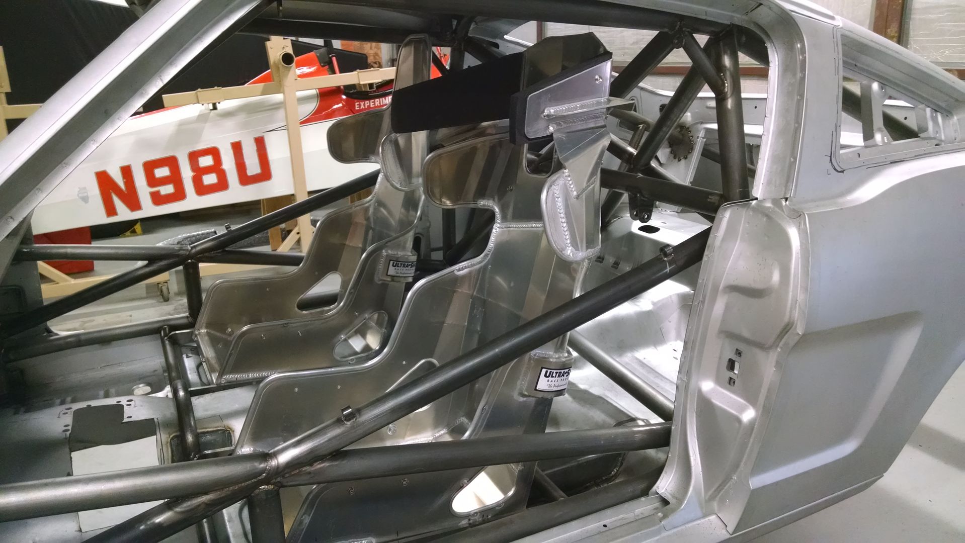
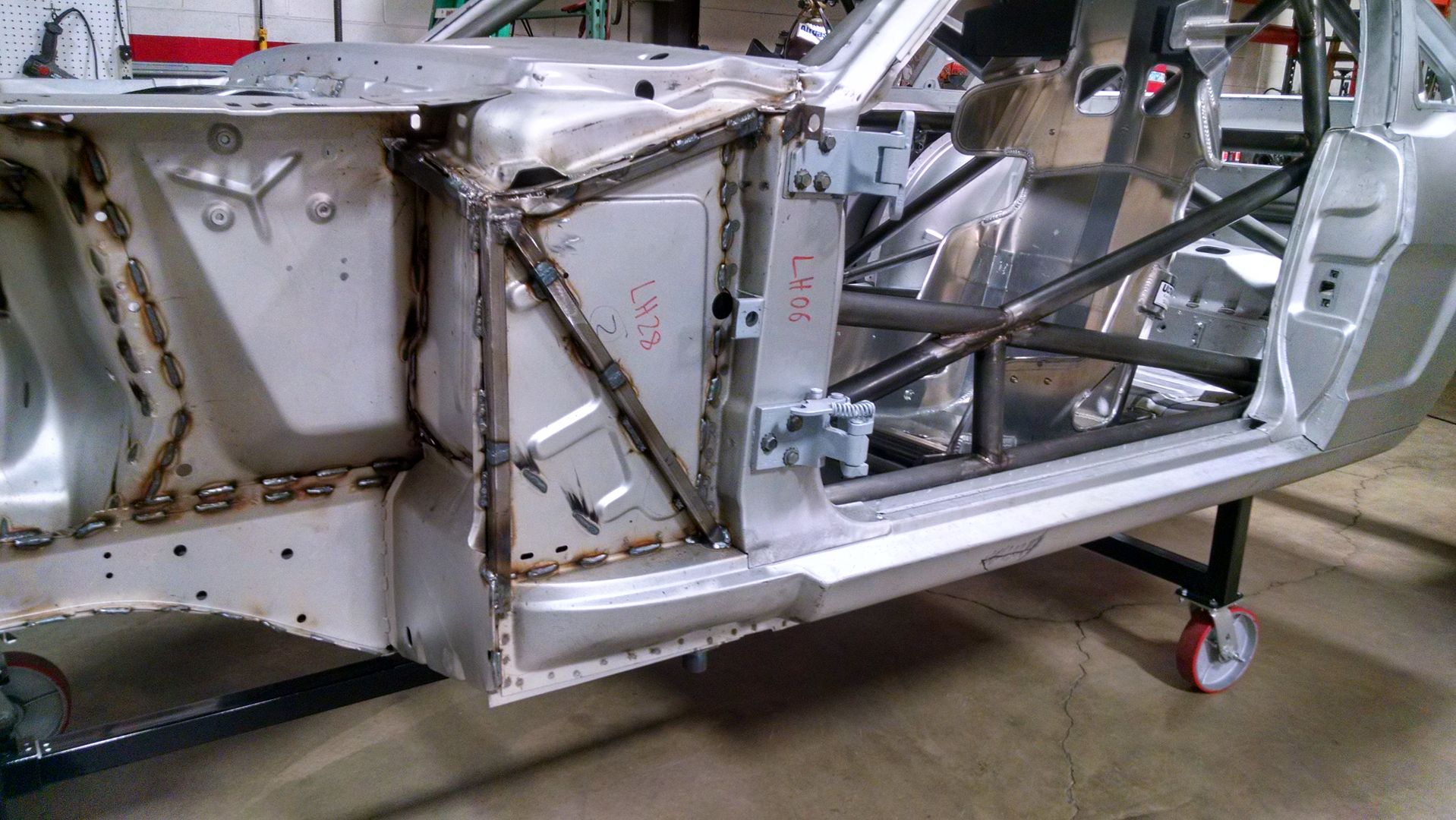
    After six weeks at the chassis place, it's back in my shop. Here are a few pics I took during the most recent round of cage and suspension work, which included.....

    Finishing up a few of the hard-to-get-at welds;
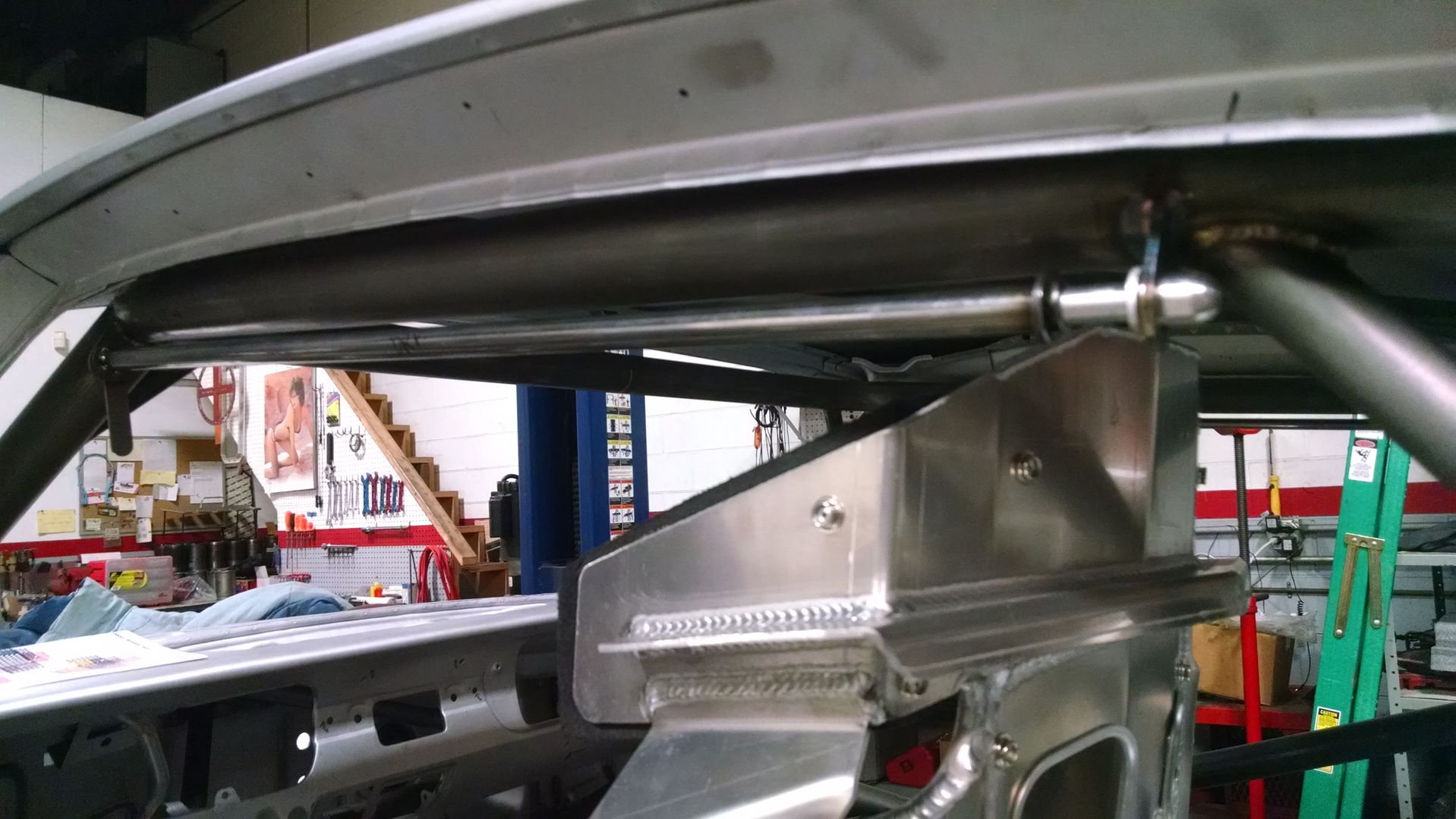
    Adding removable window nets (driver and passenger);
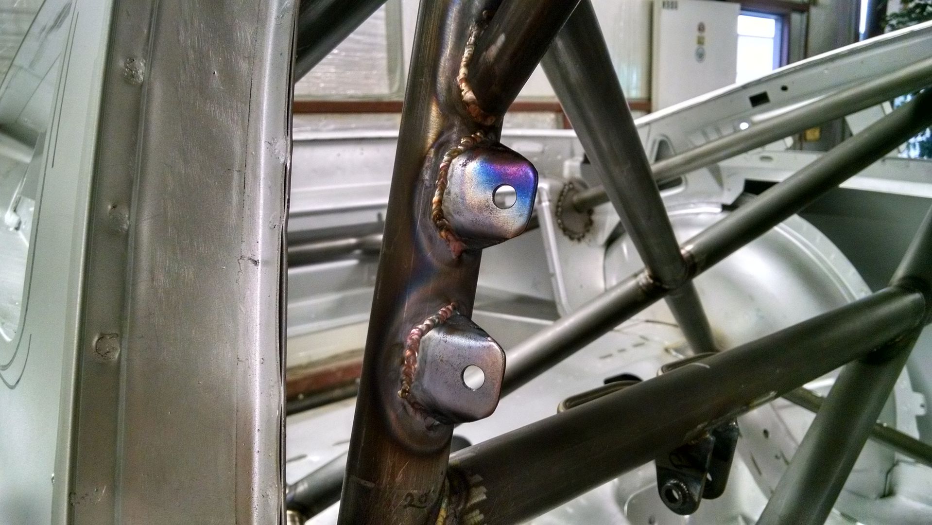
    Tabs on the cage for external access to the fire suppression activation and emergency shut-off switch;
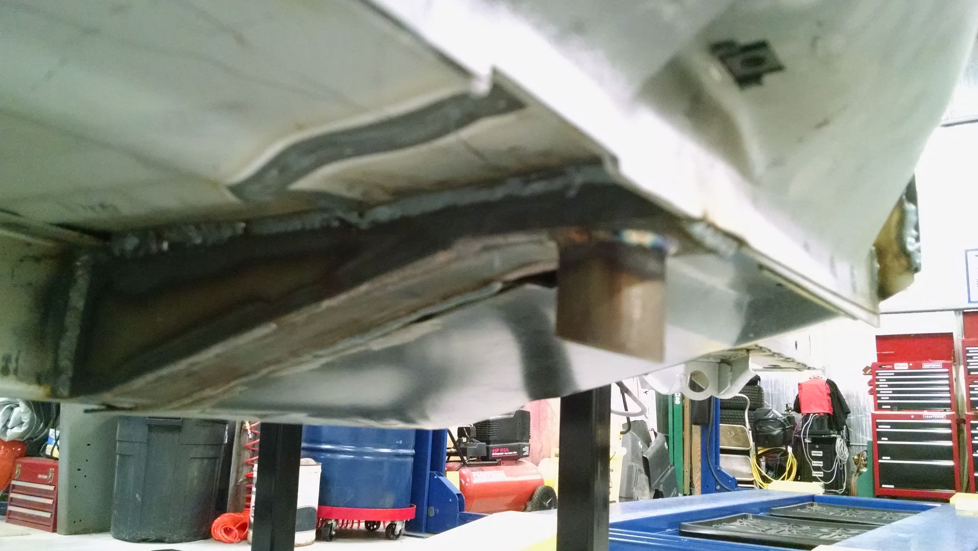
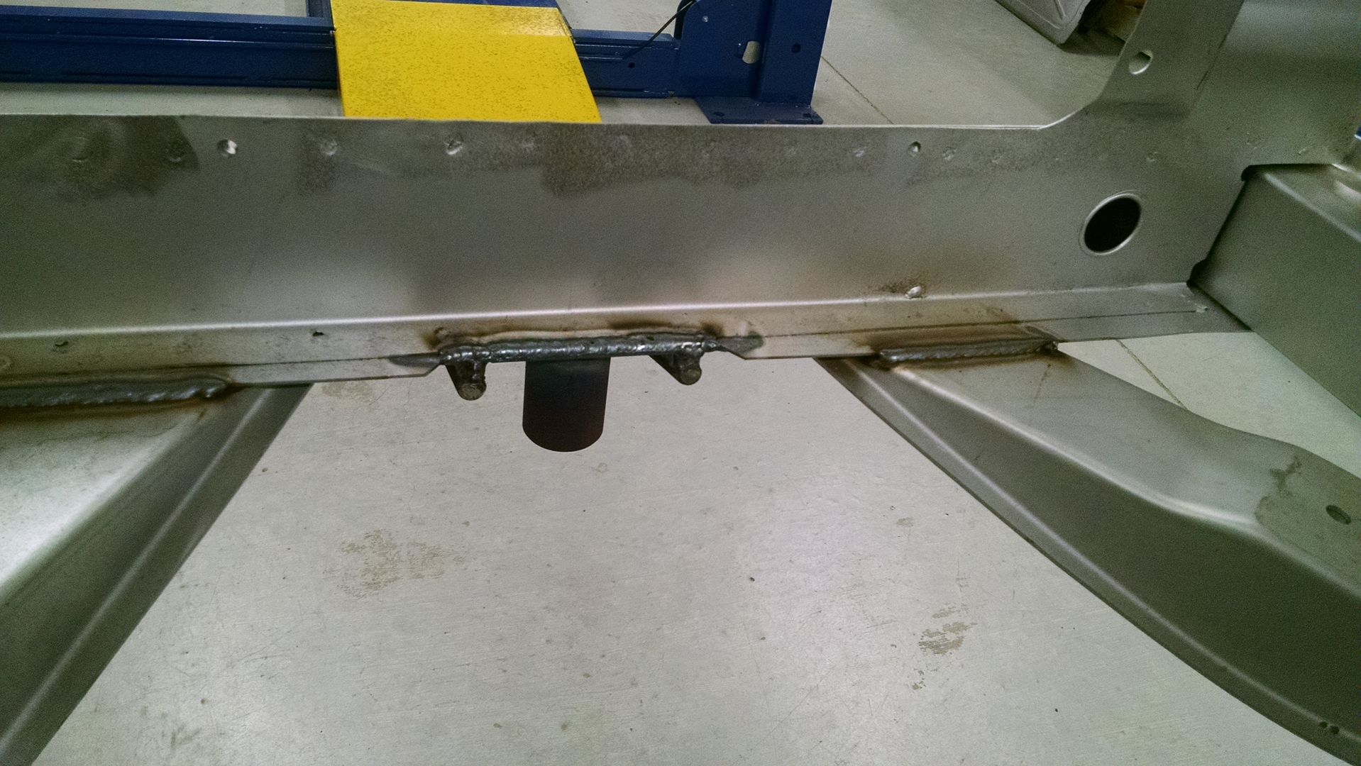
    Jacking points under the rocker reinforcements;
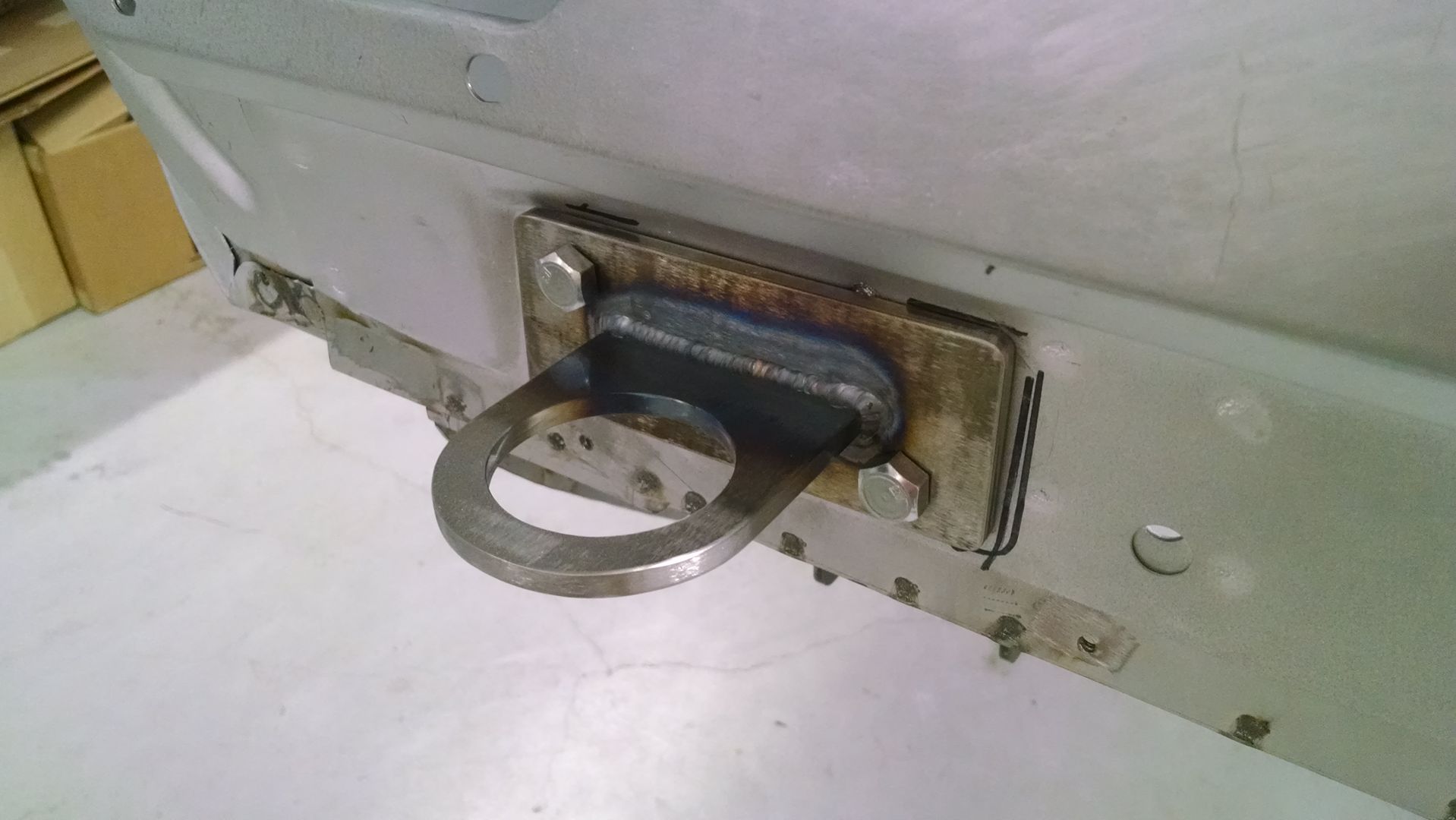
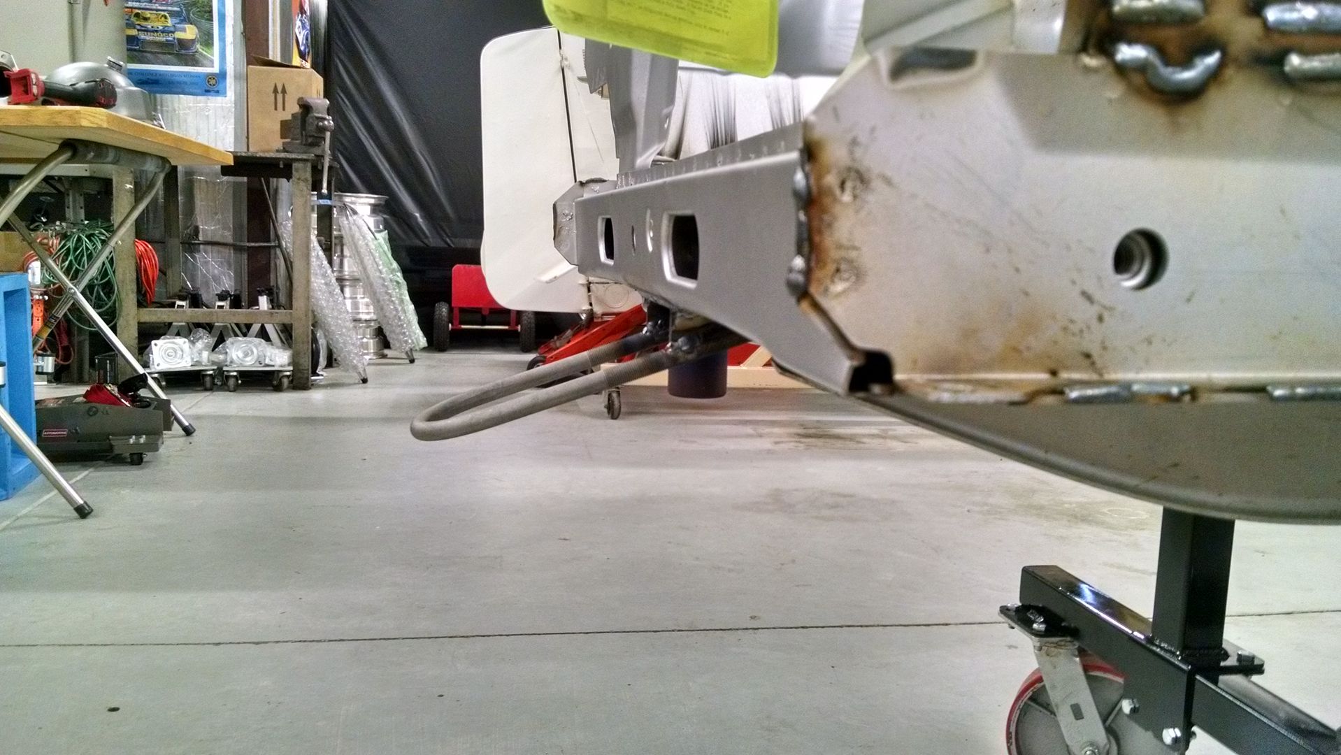
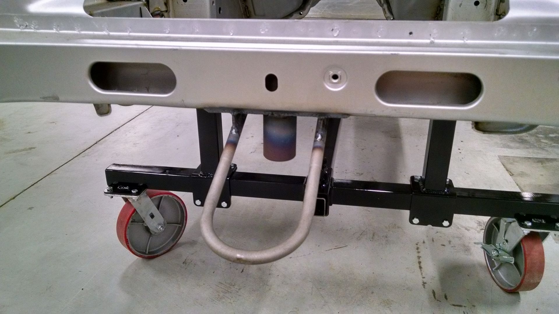
    Tow hooks front and rear - including an incorporated jacking point at the front tow hook location;
    Installation of the sliders for the leaf spring rear mounting point (instead of shackles);
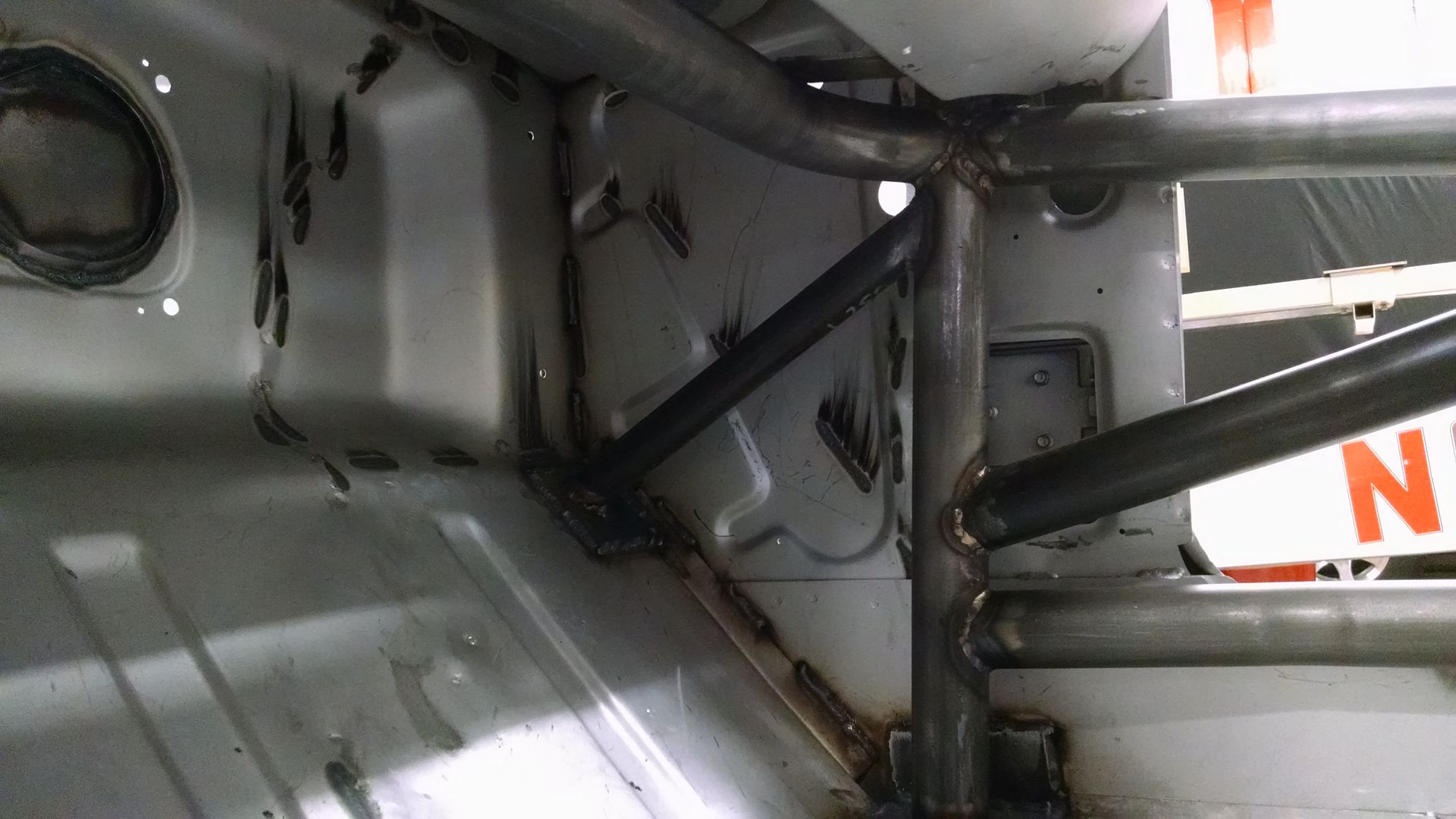
    Gusseting - under the dash and at the cage / subframe intersection;
    Completion of the "exoskeleton" for the cowl - 3/4" square tube surround that ties the cowl into the cage / "A" pillars and the front suspension;
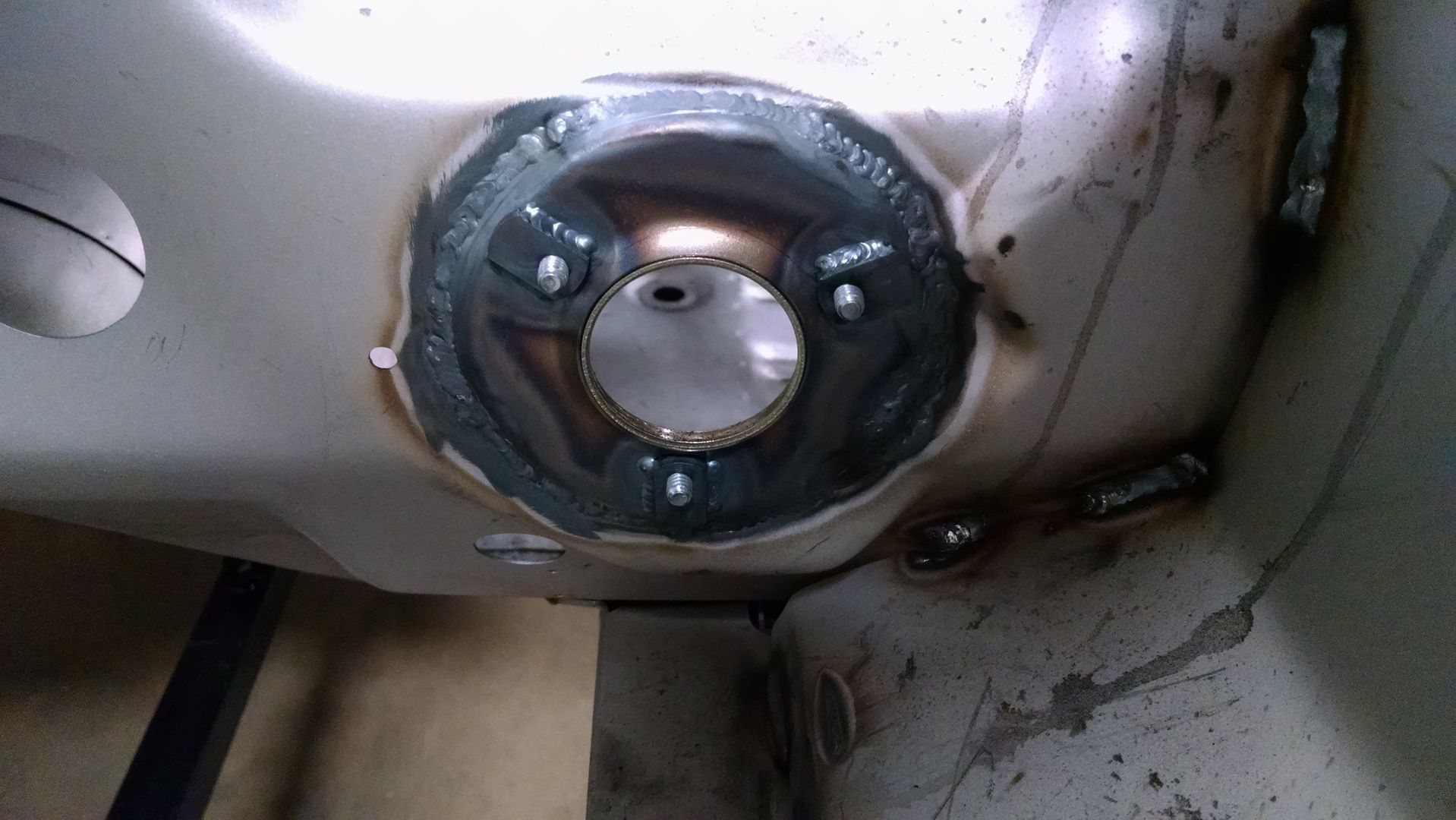
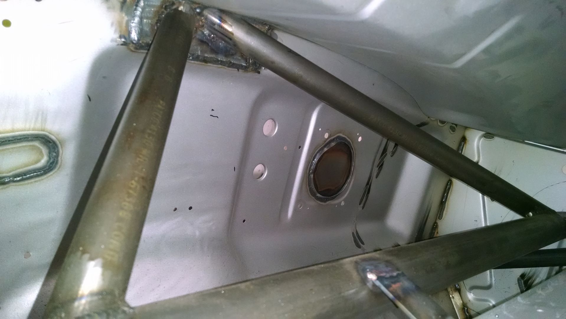
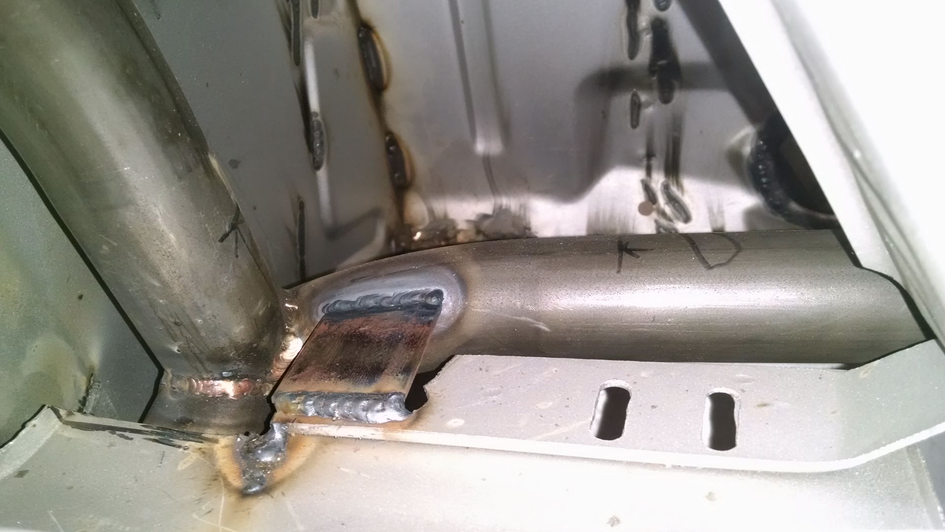
    Firewall mounting point for the lower steering shaft bearing mount; and
    Recess in the under-dash crossbar for additional steering column clearance

    Firewall work for steering shaft bearing....


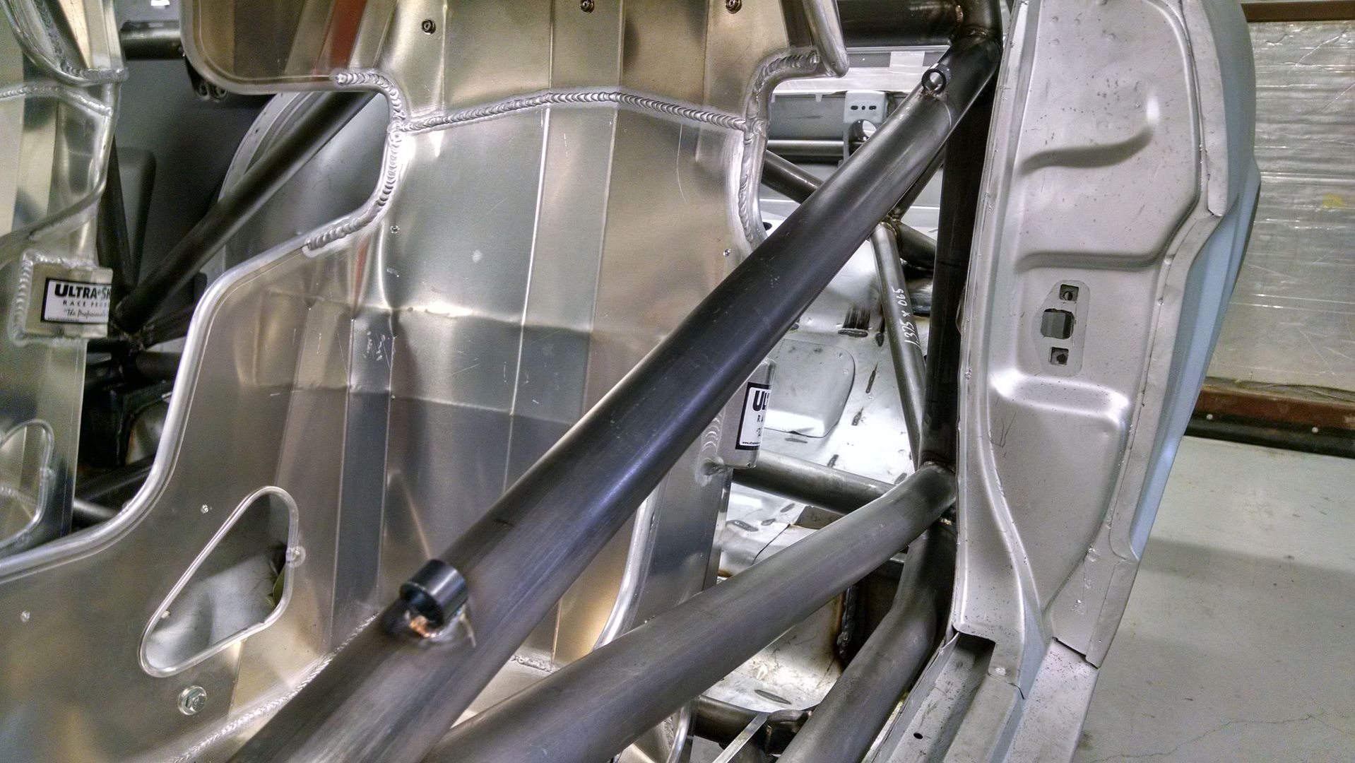
    Upper rod for driver's window net....


    Passenger side slider located to rear of subframe below trunk floor opening - not the best pic... more to come on this....


    Cowl reinforcement.....
    Later,
    Chris

    "There are no more monsters to fear, and so, we have to build our own."
    Mk3.1 #7074

  2. #82
    Out Drivin' Gumball's Avatar
    Join Date
    Feb 2011
    Location
    Blackberry Township, IL
    Posts
    2,653
    Post Thanks / Like
    Some additional pics of the latest work.......

    I made this rear tow eye that bolts to the rear bumper mount area out of 1/4" plate steel and tacked it together before letting the real welder (i.e., a guy with skill) do the final welding, since it may be used to haul my butt out of a bad spot someday:


    Here are a couple pics of the front tow eye that includes a jacking point - I also made this one following a tried-and-true formula, but delivered it to the chassis guy only tacked together for him to do the finish welding, including welding it to the car. It'll protrude about 3" out from below the R-model fiberglass valance that will be on the front when done and the thick-walled tube protruding downward will serve as a front center jacking point - the eye and the tube are welded to a piece of plate steel, which in turn is welded to the radiator core support:


    This one shows the two tabs where I'll mount the "T" handles for the fire suppression system and the emergency cut-off switch - the cut-off switch will actually be mounted on the control panel on the trans tunnel between the seats, but there will be a cable that will run to this point for external access by a corner worker:


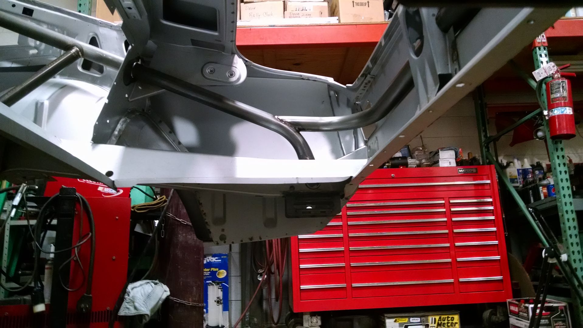
    Here is a shot of the additional triangulation that we added to the cage from the "A" pillar main tube down at a 45* angle to a pad that is mounted at the point where the toe board meets the firewall - on the outside of this is the upper point for the convertible torque boxes that were also added during the body reconstruction:


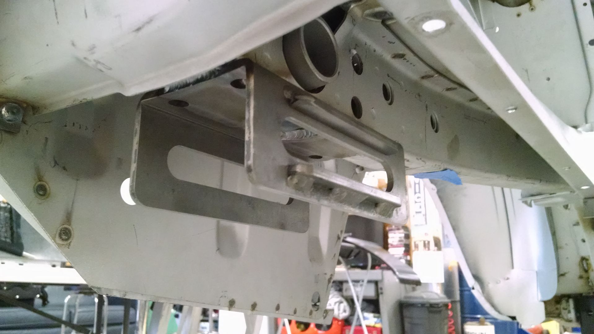
    Here's a much better picture of the leaf spring rear mount - these sliders replace the OEM shackle (which would have mounted to the large tube directly above the slider) and allow the springs to run on a set of bearings in the tracks above and below the slots:


    This shows the mounting points for the lower window net rod - due to the odd shape of the opening, I had RJS make a set of trapezoidal nets that are secured by these tubes with a pin on the bottom and by a spring-loaded rod at the top (as shown in one of the pics in the post before this):

    Last edited by Gumball; 09-08-2016 at 09:38 AM.
    Later,
    Chris

    "There are no more monsters to fear, and so, we have to build our own."
    Mk3.1 #7074

  3. #83
    Out Drivin' Gumball's Avatar
    Join Date
    Feb 2011
    Location
    Blackberry Township, IL
    Posts
    2,653
    Post Thanks / Like
    Just a few more pics......

    This is the bracing and gussets for the under dash tube - the angled braces mount to the pad that is directly behind the "export brace" mounting point inside the engine compartment - effectively connecting the cage to the front shock towers through the firewall - but through what is really a bolt-on application of the "export brace" - also, you can see one of the under dash tube gussets that connect that tube to the lower edge of the dash:


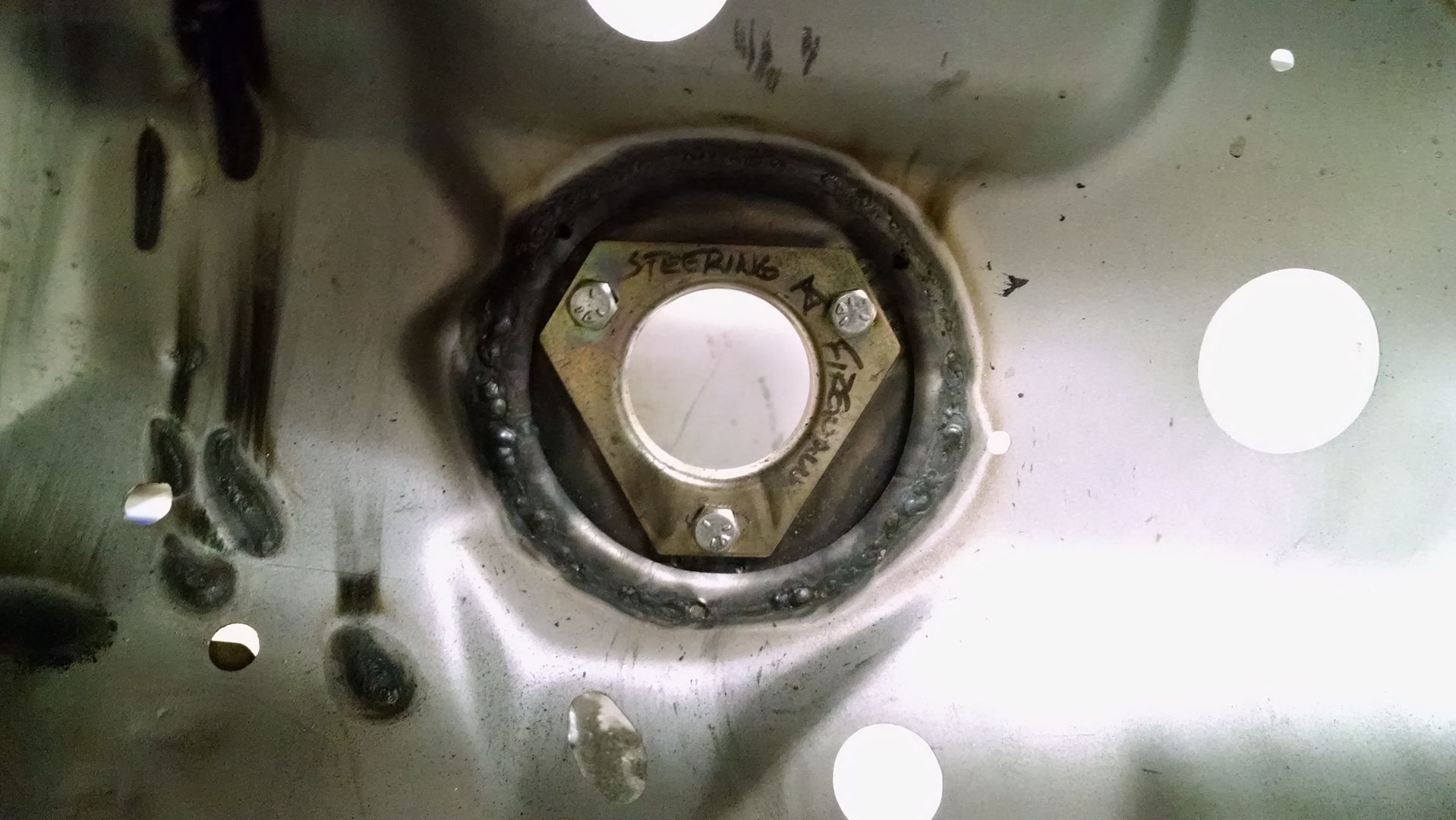
    Inside of the firewall showing one of the sides of the mounting flange for the lower steering shaft:


    And here's an overall pic of the interior as it stands now:

    Later,
    Chris

    "There are no more monsters to fear, and so, we have to build our own."
    Mk3.1 #7074

  4. #84
    Out Drivin' Gumball's Avatar
    Join Date
    Feb 2011
    Location
    Blackberry Township, IL
    Posts
    2,653
    Post Thanks / Like
    And a few more photos showing details of the recent work.

    Here is the jack bung on the underside of the reinforcement that runs sideways between the front subframe and rocker - this reinforcement ties those two areas to the floor, the front torque box, and the cage (since the front "A" pillar tube pad sits right above this on the other side of the floor pan) - this bung, which still needs final shaping, will hook onto a hydraulic jack pad and will be parallel to the ground when the jack is fully raised, lifting both the front and rear wheels on the side that is jacked up.


    This shows the detail of one of the three gussets that attach the lower dash lip to the cage tube that runs behind the dash - the lower part of the dash was originally attached at only the sides, but those attachment points were removed to make room for the cage tubing. You can also see the full welding that was done to the front lower strut rod supports where they meet the radiator core support.


    And finally, one more shot of the front tow eye / jack point... this time from the engine compartment side showing how it's welded to the radiator core support.

    Later,
    Chris

    "There are no more monsters to fear, and so, we have to build our own."
    Mk3.1 #7074

  5. #85
    Out Drivin' Gumball's Avatar
    Join Date
    Feb 2011
    Location
    Blackberry Township, IL
    Posts
    2,653
    Post Thanks / Like

    Considering Wilwood pedals and Tru-Bar balance system

    Hey guys,

    I'm thinking about using the Wilwood brake and clutch pedal system with their Tru-Bar balance set up. Since I will be installing a hydraulic clutch, this seems a logical next step.

    Thoughts and experiences with the Wilwood stuff from those of you who are using it in your FFR or other cars are appreciated.
    Later,
    Chris

    "There are no more monsters to fear, and so, we have to build our own."
    Mk3.1 #7074

  6. #86
    Out Drivin' Gumball's Avatar
    Join Date
    Feb 2011
    Location
    Blackberry Township, IL
    Posts
    2,653
    Post Thanks / Like
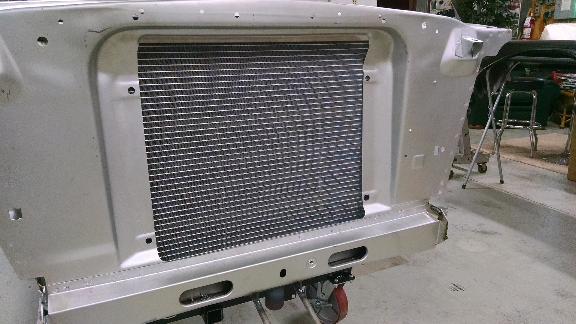
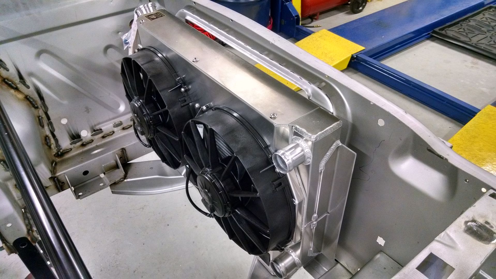
    This ought to keep things cool - you'd think I'm planning on an engine that generates a bit of heat.

    Still need to trim the recessed area of the core support to make the opening match the oversized area of this radiator, but this gives an idea of how it will fit.


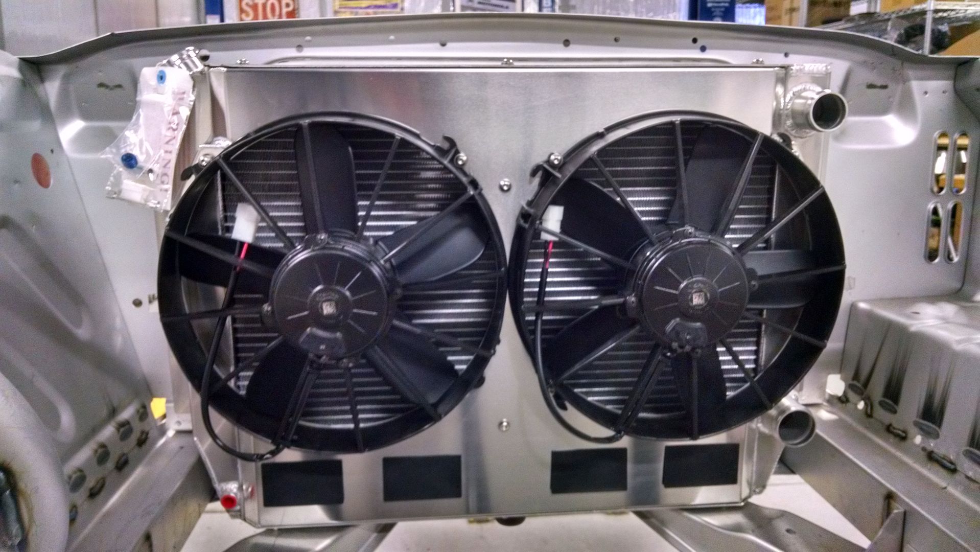
    These fans should move a bit of air... about 3200 cfm, in fact:


    The black rectangles at the bottom are rubber flaps over cut-outs that relieve pressure in the shroud at higher speeds - oh, say like around 150 mph on a couple of the longer stretches at Road America:

    Last edited by Gumball; 10-07-2016 at 07:53 AM.
    Later,
    Chris

    "There are no more monsters to fear, and so, we have to build our own."
    Mk3.1 #7074

  7. #87
    Out Drivin' Gumball's Avatar
    Join Date
    Feb 2011
    Location
    Blackberry Township, IL
    Posts
    2,653
    Post Thanks / Like
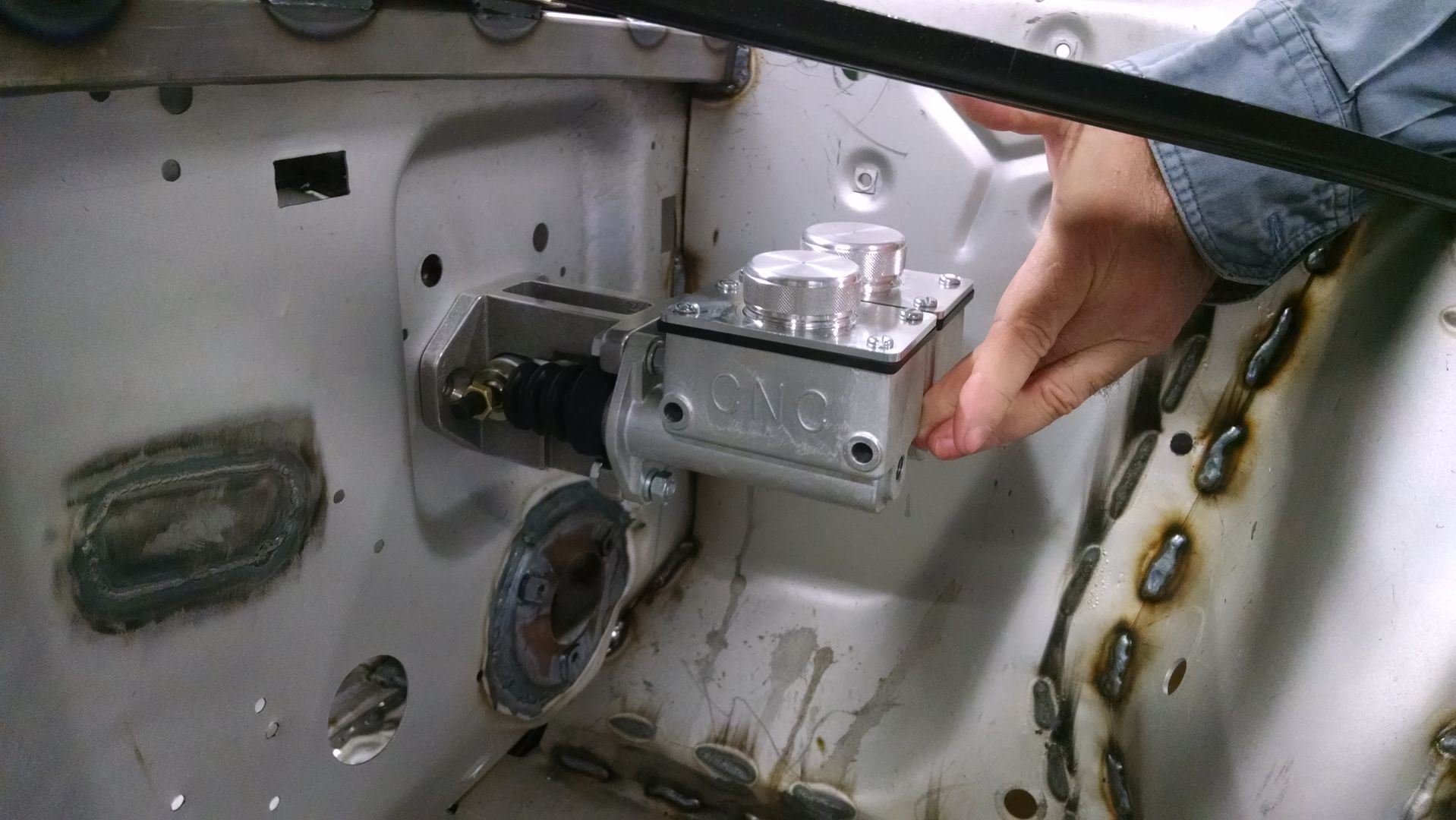
    As an alternative to the Wilwood pedal assembly mentioned above in post #85, here's something a friend just bought for his Mustang and brought by my shop for me to do a test fit - it's a dual master cylinder assembly by CNC with an adjustable balance bar rod. The balance bar works by being connected to a knob in the car that changes the fulcrum applying pressure to the master cylinder pushrods, just like the Wilwood Tru-Bar set-up.... only this works using the original pedal assembly.

    Later,
    Chris

    "There are no more monsters to fear, and so, we have to build our own."
    Mk3.1 #7074

  8. #88
    Out Drivin' Gumball's Avatar
    Join Date
    Feb 2011
    Location
    Blackberry Township, IL
    Posts
    2,653
    Post Thanks / Like
    I've been doing some more mock-up work, getting ready to install some additional forward section bracing and shock tower reinforcements.

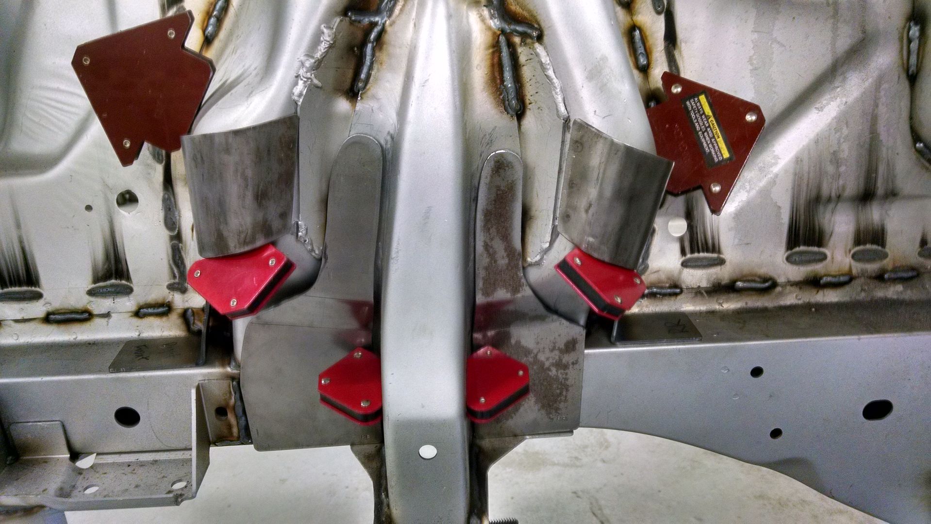
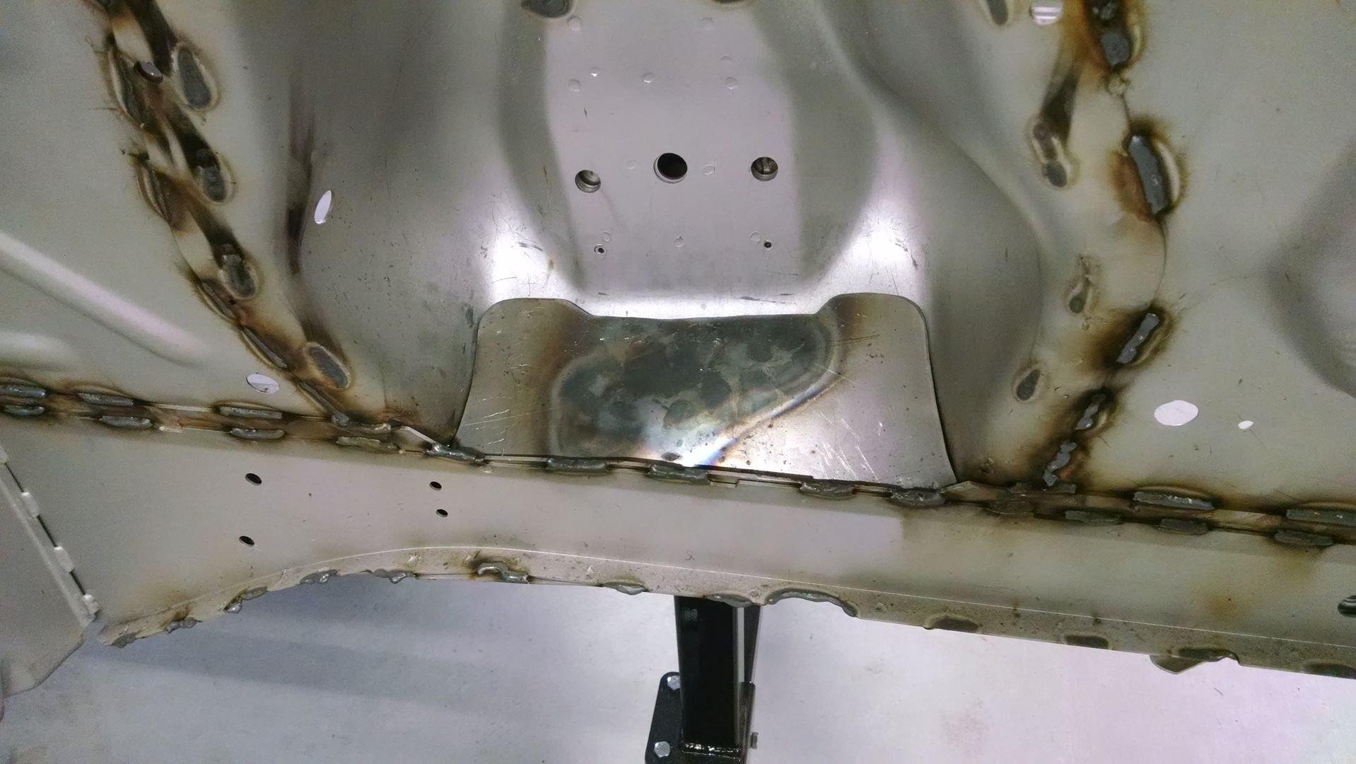
    The shock tower reinforcement is a kit sold by the "Dr. Gas" guys and includes six pieces per side for the inner shock tower area (this mimics the big-block cars from later years, as well as the Boss 302s) and although the kit did come with a couple pieces of flat stock for the outer pocket, I made my own so that they are more like what the old Boss 302 chassis prep manual put out by Ford back in '70 recommends.

    Here's the full reinforcement kit held in place with welding magnets - the side pieces that sit on top of the subframe rails are hard to see in this pic:


    This pic shows the panel covering the outer pocket, which rises at a 45* angle from the inner lip of the subframe - note the pilot holes drilled for the 1 3/4" upper control arm drop:


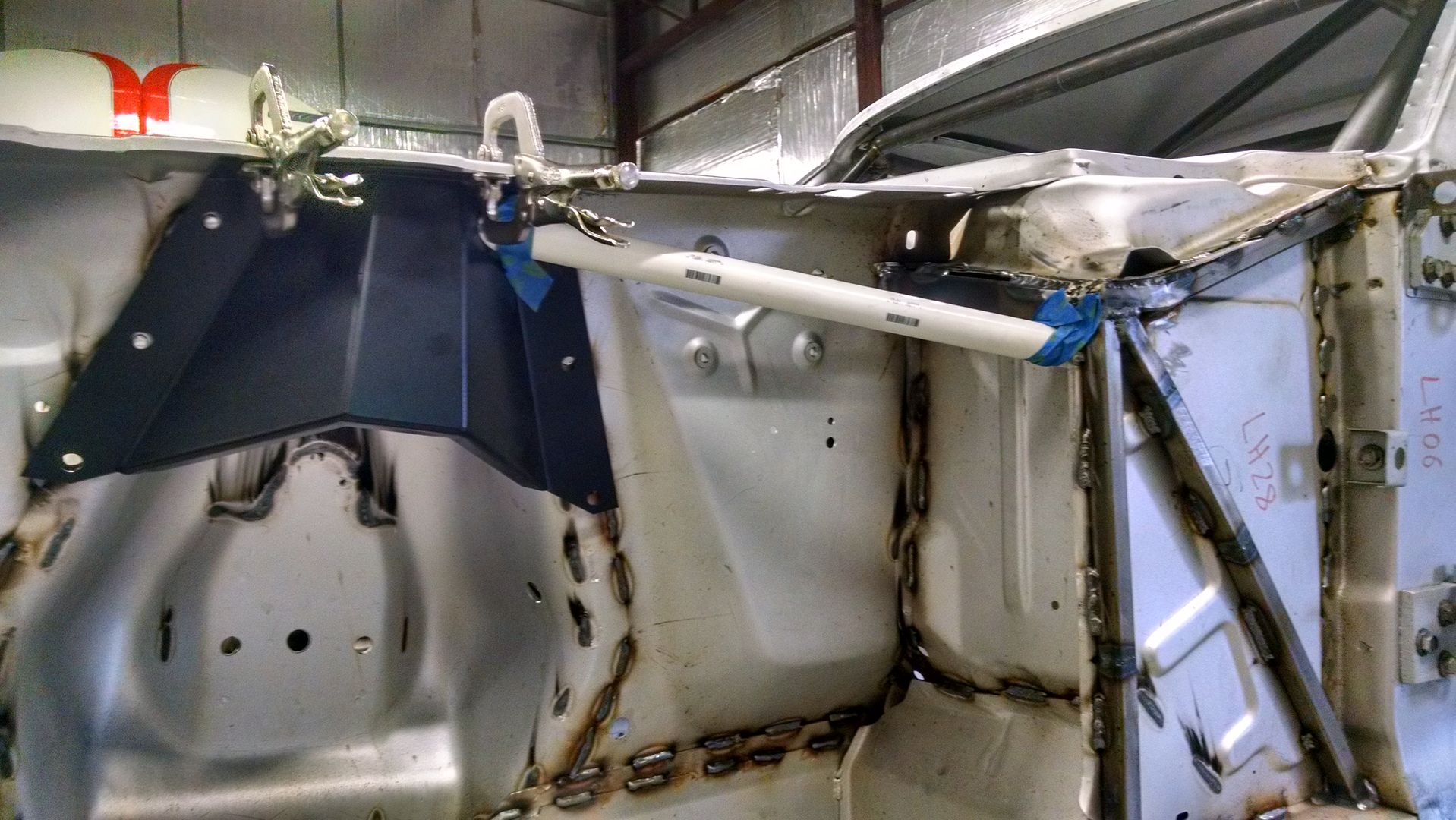
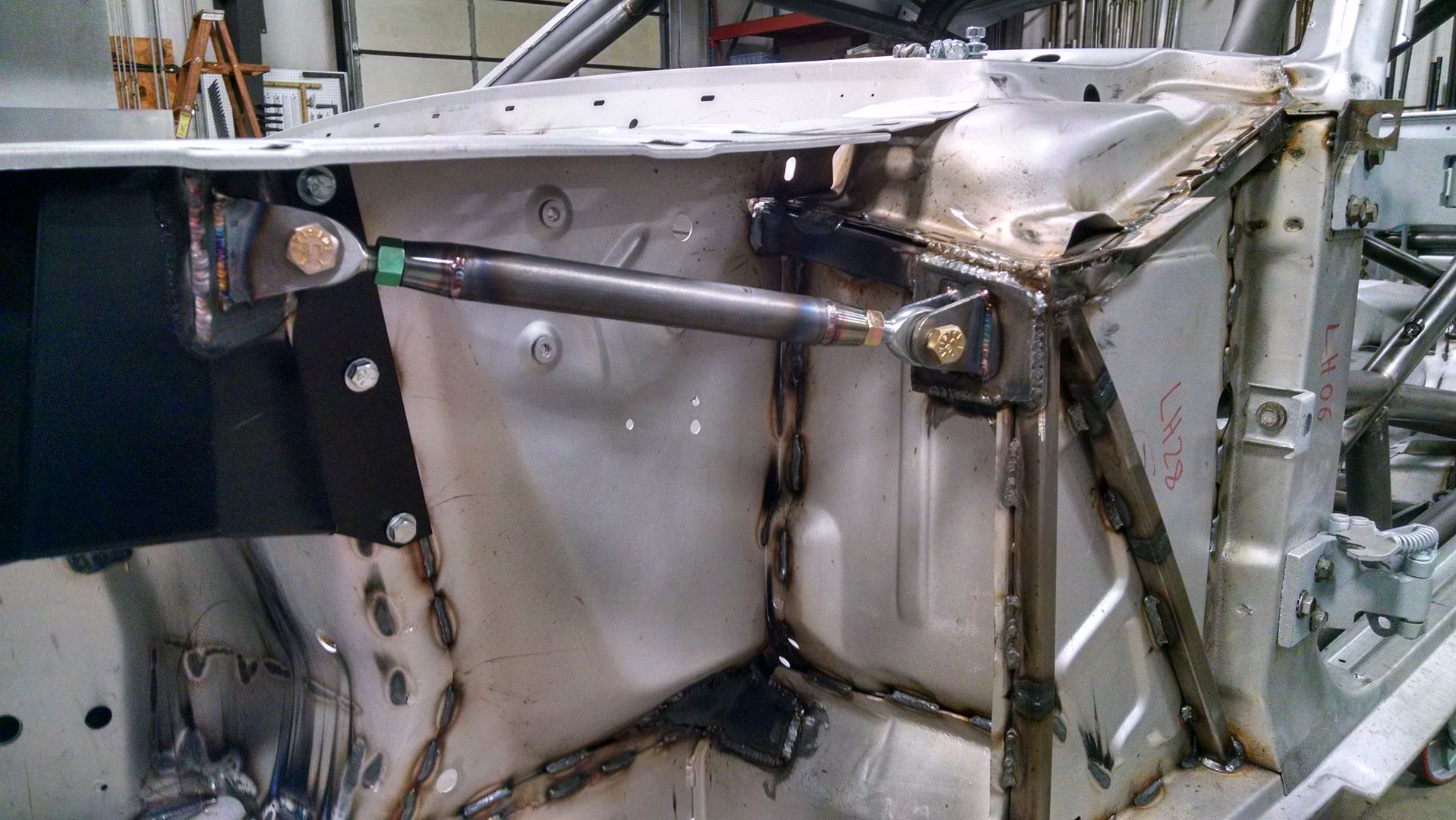
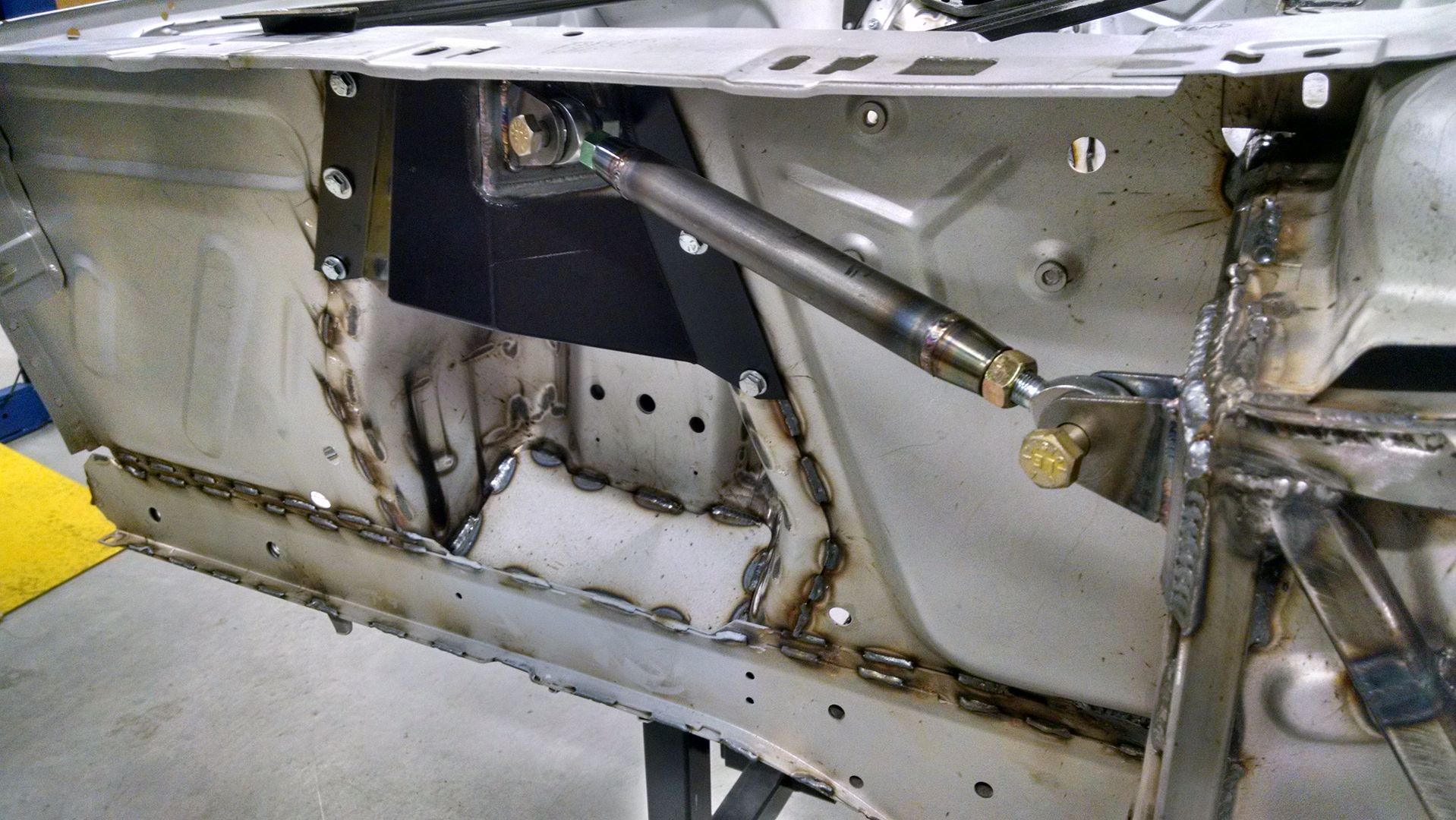
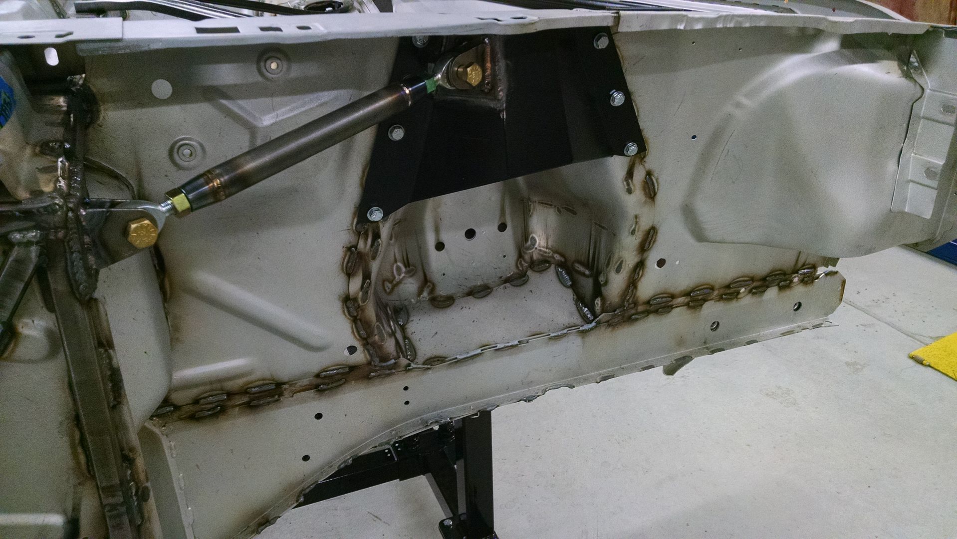
    And this is a shot of the mock-up of the final front section stiffener - a strut rod that will run from the upper outside corner of the reinforced cowl to the spring / shock cover... this will be made using 4130 chrome moly tubing with spherical rod ends so that the spring / shock covers can be removed.

    Later,
    Chris

    "There are no more monsters to fear, and so, we have to build our own."
    Mk3.1 #7074

  9. #89
    Out Drivin' Gumball's Avatar
    Join Date
    Feb 2011
    Location
    Blackberry Township, IL
    Posts
    2,653
    Post Thanks / Like
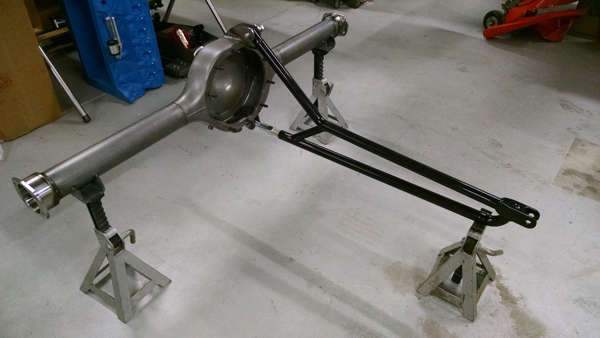
    The shell is back at the chassis shop getting the reinforcements that I posted above welded into place. When I dropped it off, the rear end housing was done, and now has a large filler, drain in the bottom, a jack bung surrounding the drain plug area, a temp sensor bung, and brackets for the torque arm. Here's a pic of the torque arm mock-up (no lock nuts in place on the lower pivot adjustment). I just have to work on the math to ensure that the front mount I use doesn't introduce any bind into the system and it'll be ready to go. Torque arm is made by Total Control Products and is 36" long - it's the version for a Cougar with a nine inch rear end.

    Also, the rear end housing was made by Moser and includes 3" tubes and uses the large "Torino" bearings.

    Later,
    Chris

    "There are no more monsters to fear, and so, we have to build our own."
    Mk3.1 #7074

  10. #90
    Out Drivin' Gumball's Avatar
    Join Date
    Feb 2011
    Location
    Blackberry Township, IL
    Posts
    2,653
    Post Thanks / Like
    I dropped by the chassis shop last night to check on the status of this final round of welding and it looks like they're just about done - should be back in my shop by this weekend. I'll post more pics as soon as it's back in my care.

    Here are a couple pics....

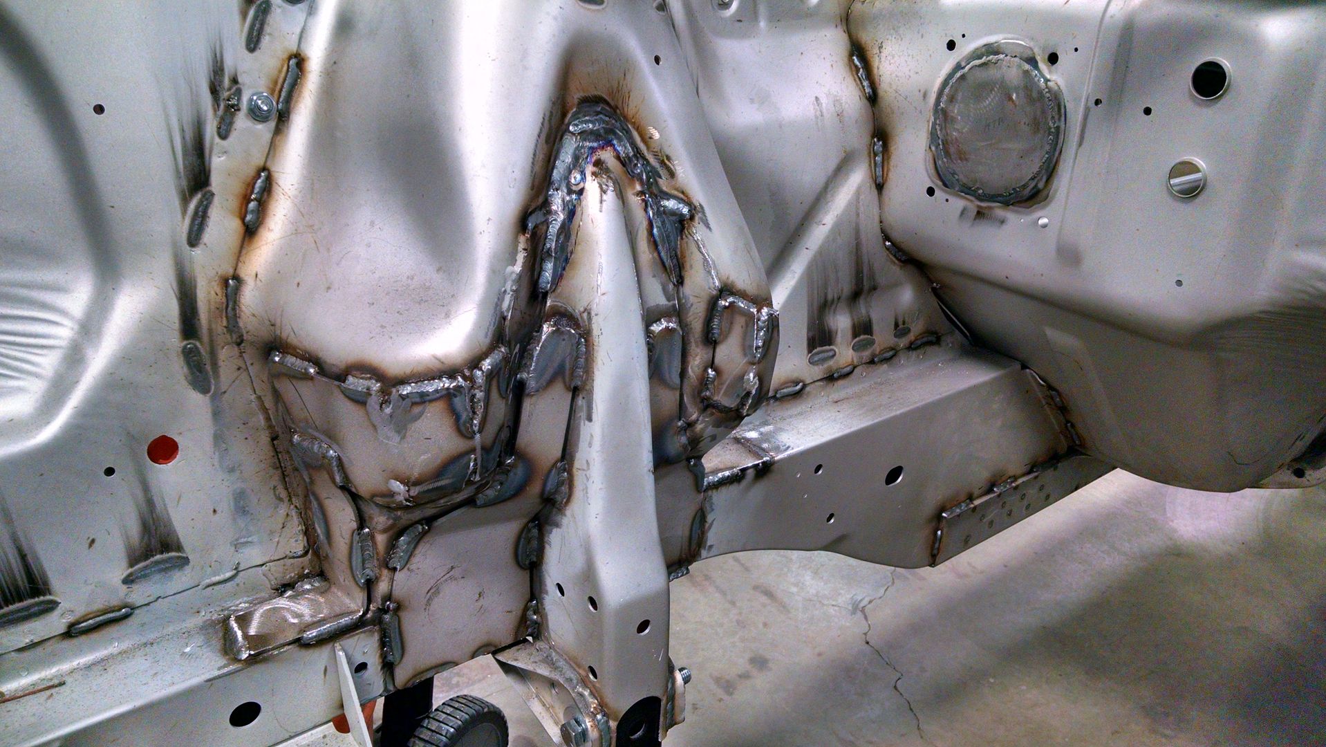
    This shows the finished reinforcement panels on the inside of the shock towers. These will greatly increase the strength of the lower area of the towers and hopefully avoid any cracking issues that would come from heavy track use. Note that there are no holes for the upper control arms visible, but the lowered mounting points were pre-drilled (pilot holes only) in the existing metal and are accessible from the outside. I'll only drill those, though, not the original holes. Something else evident in this pic is the fact that the chassis guys spent a little more time re-fitting the reinforcement panels, including a few pie-slices, to make sure that they are completely flush against the original metal.


    This is the removable strut rod that we added from the reinforced cowl area to the spring cover - one per side. It's removable so that the spring cover can remain a removable part. And, while the spring cover is a fairly flimsy piece of sheetmetal (about .090"), this will provide some incremental support at the outside of the shock tower.

    Later,
    Chris

    "There are no more monsters to fear, and so, we have to build our own."
    Mk3.1 #7074

  11. #91
    Out Drivin' Gumball's Avatar
    Join Date
    Feb 2011
    Location
    Blackberry Township, IL
    Posts
    2,653
    Post Thanks / Like
    Here are a couple of additional pics of the latest round of chassis work - stiffening the front shock towers.....

    Driver's side showing the 45* angled plate spanning the pocket that is a weak point on the original cars:


    Same thing, but passenger side - these plates are in part the reason for the additional reinforcement patches on the inner shock tower, as they move forces from the subframe up to the now reinforced area:

    Later,
    Chris

    "There are no more monsters to fear, and so, we have to build our own."
    Mk3.1 #7074

  12. #92
    Out Drivin' Gumball's Avatar
    Join Date
    Feb 2011
    Location
    Blackberry Township, IL
    Posts
    2,653
    Post Thanks / Like
    I didn't realize how long it's been since I've posted an update - unfortunately, it's because year end at work and other things have really gotten in the way of my car hobby for the past couple of months (except for the side-trip to pick up a garage mate for the Rustang).

    I received one of those "clip-under-the-hood" LED bar lights for Christmas, so was playing around with it today and took this pic of the Rustang - light bar is hanging from the cage and all of the other lights in my shop were off. This really shows some of the roll cage detail... enjoy.

    Later,
    Chris

    "There are no more monsters to fear, and so, we have to build our own."
    Mk3.1 #7074

  13. #93
    Out Drivin' Gumball's Avatar
    Join Date
    Feb 2011
    Location
    Blackberry Township, IL
    Posts
    2,653
    Post Thanks / Like
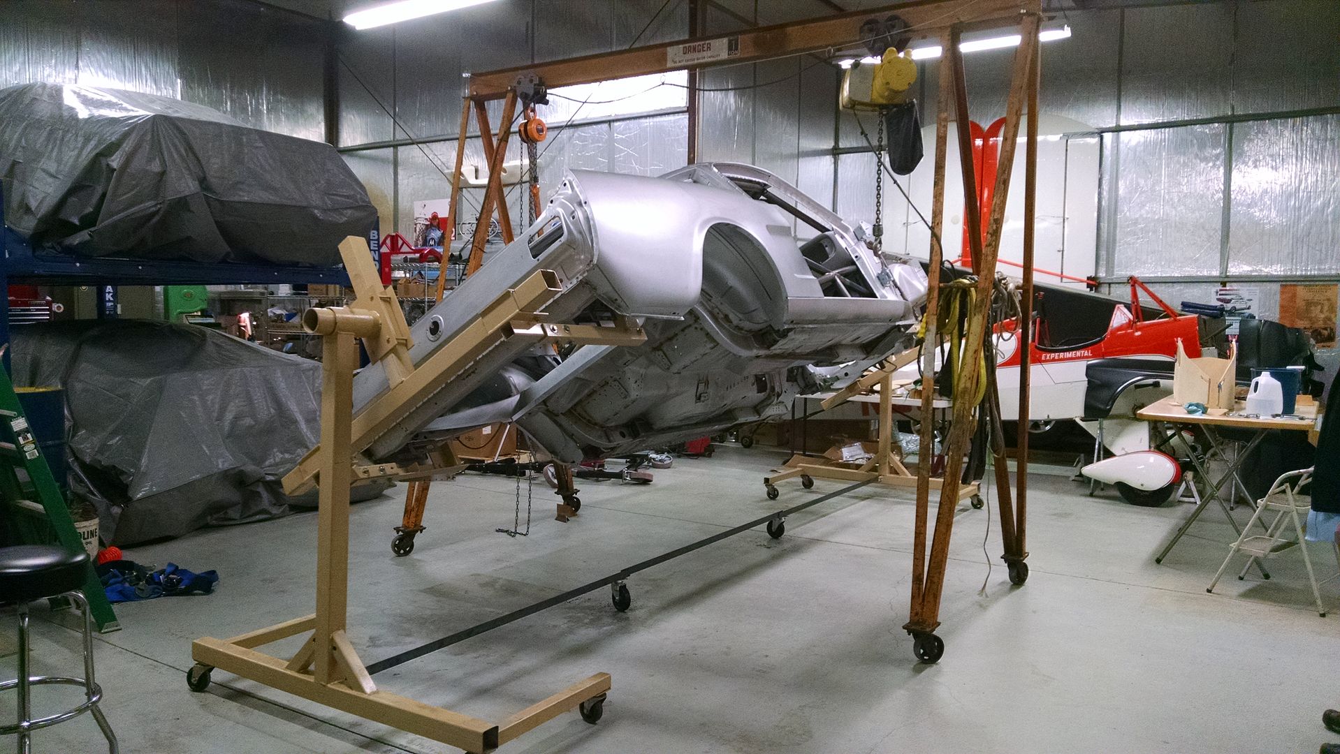
    Up in the air finally and on the spit for clear access to the entire car. I bought this rotisserie from a local guy who built it from some plans and used it for a few restoration - only cost me three hundred bucks... basically the cost of the steel, welding gas, and rod. Not adjustable like the store-bought variety, what with their hydraulic jacks and such, but with the use of a rolling gantry lift from my next door neighbor at the airport (he uses it to remove the prop from his WWII warbird), it was easy to lift it up and then adjust it to find the center of gravity. I can rotate it with one hand and it's a really stable work platform.

    Later,
    Chris

    "There are no more monsters to fear, and so, we have to build our own."
    Mk3.1 #7074

  14. #94
    Out Drivin' Gumball's Avatar
    Join Date
    Feb 2011
    Location
    Blackberry Township, IL
    Posts
    2,653
    Post Thanks / Like
    Another shot...

    Later,
    Chris

    "There are no more monsters to fear, and so, we have to build our own."
    Mk3.1 #7074

  15. #95
    Senior Member MPTech's Avatar
    Join Date
    Feb 2011
    Location
    St. Louis, MO
    Posts
    1,246
    Post Thanks / Like
    Blog Entries
    8
    Really enjoying your build Chris, you do Class-A work on every project! That welding and re-inforcement is a work of art!
    F5R #7446: MK4, 302, T5 midshift, 3.55 Posi IRS, 17" Halibrands
    Delivered 4/4/11, First start 9/29/12, Licensed 4/24/13, off to PAINT 2/15/14!! Wahoo!

  16. #96
    Out Drivin' Gumball's Avatar
    Join Date
    Feb 2011
    Location
    Blackberry Township, IL
    Posts
    2,653
    Post Thanks / Like
    This is the first time I've used a rotisserie for a restoration / build, so it's been fun for the past few days just spinning the body around and looking at all the various parts I have to work on over the next few months.

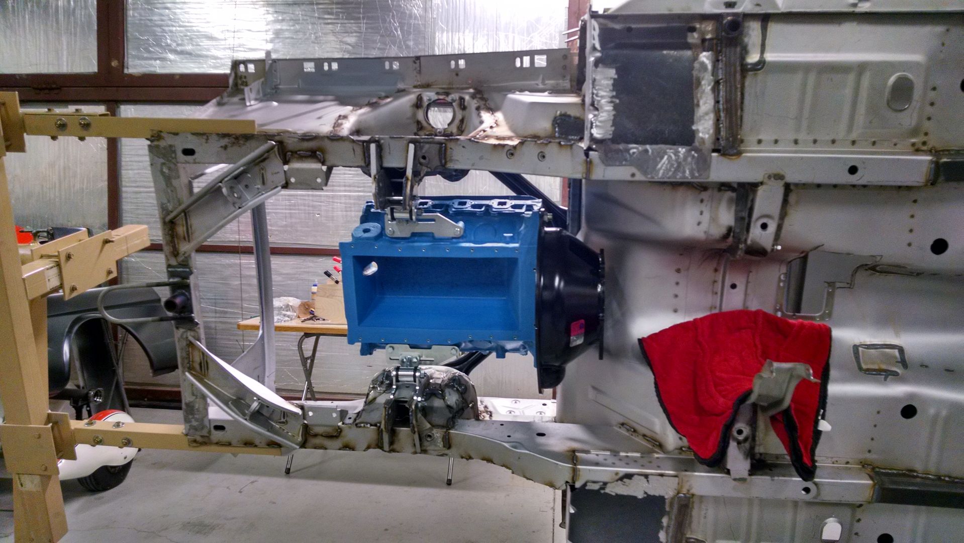
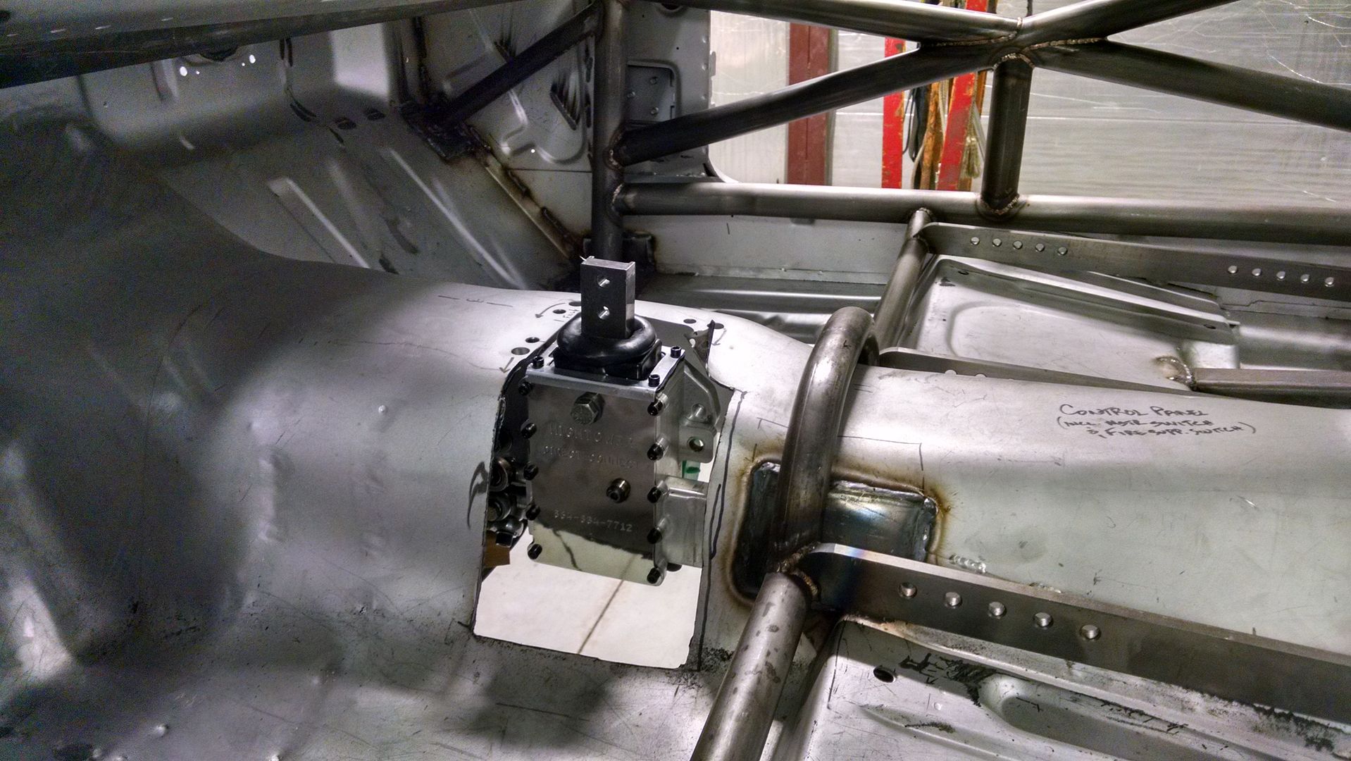
    Yesterday, I used the mock-up block to get the transmission fitted again - and this time, the trans went right in place and the shifter fell smack in the middle of the rough-cut hole I made in the floorpan after my first attempt. Since I'm using a Jerico trans, the basic outer dimensions match that of a Ford toploader. But, the Hightower Direct Connect shifter is a bit of a wild card, in that it's taller than a stock shifter mechanism and is mounted off to the left side of the tail housing, closer to the driver.

    This time, instead of struggling to get the trans in place with the body cart supporting the body, I just rotated the body 90 degrees after bolting the fake block and bellhousing in place and, with the help of a friend and some padding on the cross member, just slipped the trans in place. After securing the cross member, we just rolled the body back level and found that the shifter was just about where I wanted it to fall. I did loosen the adjustable motor mounts so I could slide the assembly forward about an inch, but final placement will have to wait until I get the headers in place to see how everything clears the reinforced shock towers. The plan is to get the engine as far to the passenger side and as close to the cowl as possible, without having any interference issues.


    Later,
    Chris

    "There are no more monsters to fear, and so, we have to build our own."
    Mk3.1 #7074

  17. #97
    Out Drivin' Gumball's Avatar
    Join Date
    Feb 2011
    Location
    Blackberry Township, IL
    Posts
    2,653
    Post Thanks / Like
    As you can tell from the last picture in the post above, I have to construct a "bump-out" on my transmission tunnel to accommodate the Hightower shifter, which sits higher and farther towards the driver than a shifter would on a top loader. Since I have to do a bunch of other metal fabrication, I've added yet another sheet metal tool to the shop....

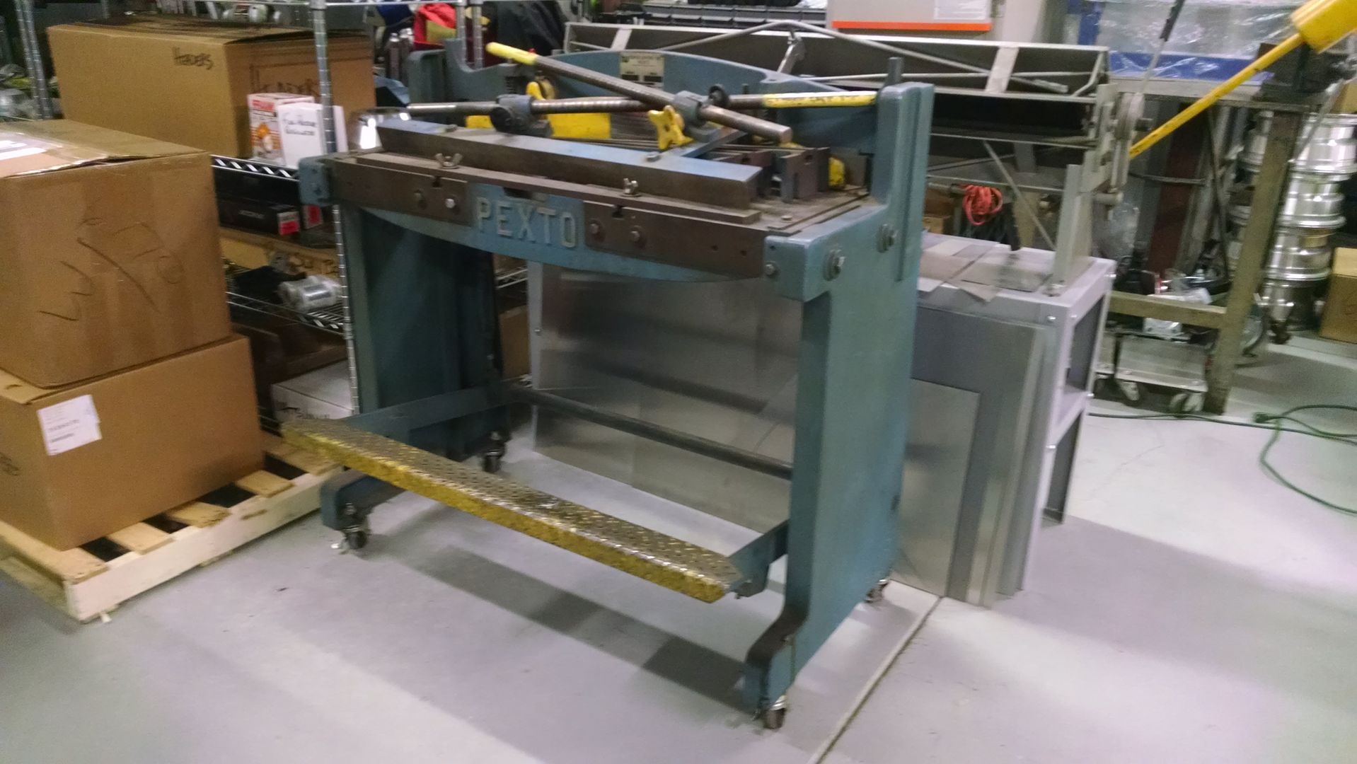
    My "new-to-me" old Pexto foot shear should come in handy....

    Found it locally on craigslist and it came complete with all of its original accessories (that's what is piled on top of it in this pic)....

    Later,
    Chris

    "There are no more monsters to fear, and so, we have to build our own."
    Mk3.1 #7074

  18. #98
    Senior Member FFRSpec72's Avatar
    Join Date
    Feb 2011
    Location
    Kirkland, WA
    Posts
    2,256
    Post Thanks / Like
    Quote Originally Posted by Gumball View Post
    As you can tell from the last picture in the post above, I have to construct a "bump-out" on my transmission tunnel to accommodate the Hightower shifter, which sits higher and farther towards the driver than a shifter would on a top loader. Since I have to do a bunch of other metal fabrication, I've added yet another sheet metal tool to the shop....

    My "new-to-me" old Pexto foot shear should come in handy....

    Found it locally on craigslist and it came complete with all of its original accessories (that's what is piled on top of it in this pic)....

    36" ?
    Tony Nadalin
    2022 SOVREN Championship
    2018 SOVREN Big Bore Champion
    2015 SCCA Oregon Region VP3 Champion
    2012 ICSCC ITE Class Champion
    FFR MkII Challenge Car, Spec Racer, Street Legal, SCCA, ICSCC and NASA Racing

  19. #99
    Out Drivin' Gumball's Avatar
    Join Date
    Feb 2011
    Location
    Blackberry Township, IL
    Posts
    2,653
    Post Thanks / Like
    Quote Originally Posted by FFRSpec72 View Post
    36" ?
    Yep - it's a model #137, so 36" cutting blades.
    Later,
    Chris

    "There are no more monsters to fear, and so, we have to build our own."
    Mk3.1 #7074

  20. #100
    Out Drivin' Gumball's Avatar
    Join Date
    Feb 2011
    Location
    Blackberry Township, IL
    Posts
    2,653
    Post Thanks / Like
    Latest update is on a work-in-progress... making a bump-out for the transmission tunnel to accommodate the Jerico and it's shifter. Although the Jerico mimics the size and shape of a Ford top loader, the shifter is in a different location, especially on mine since I'm using a version that has the shift rods going through the inside of the housing from the rear instead of along the outside of the transmission case.

    Here's a pic of the huge hole I had to cut into the new floor on my car:


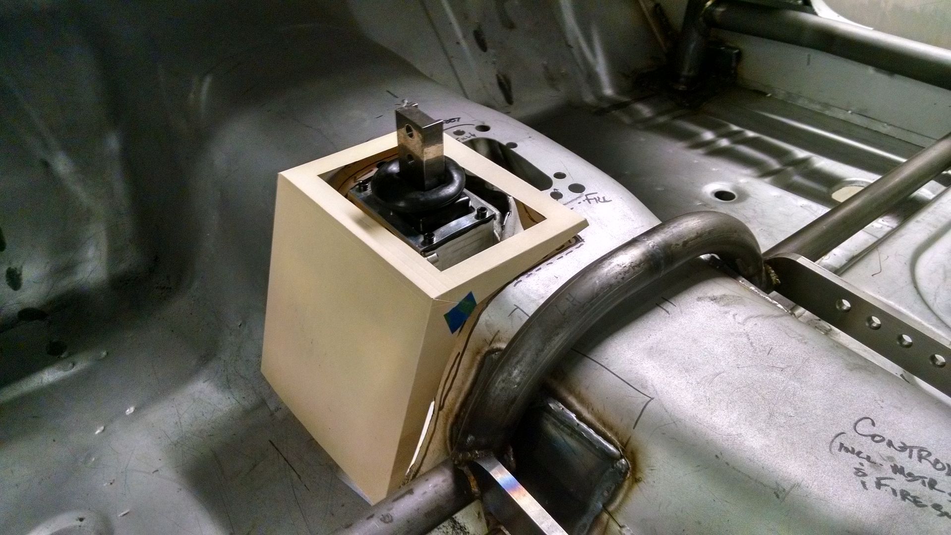
    And this is the template I made out of card stock to start the mock-up of the bump-out that I'll fabricate out of sheetmetal (using my "new to me" shear and finger brake):


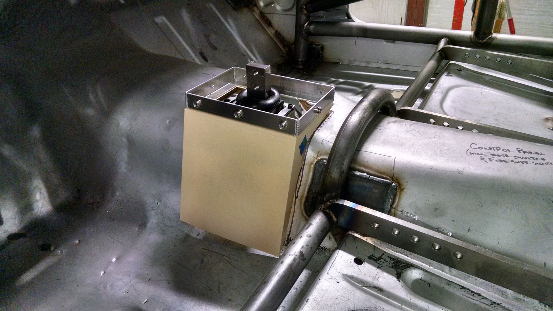
    I bought a fire/oil proof shifter boot from Joe's Racing that comes with this nifty base, complete with snaps to allow for the easy removal of the boot to fix the inevitably loose shift lever bolts on the grid just before heading out on track. Here's a pic of how the base for the boot will fit on top of the bump-out - should give a nice finished look when done:


    Now to just transfer all this into metal and get it welded together.
    Later,
    Chris

    "There are no more monsters to fear, and so, we have to build our own."
    Mk3.1 #7074

  21. #101
    Out Drivin' Gumball's Avatar
    Join Date
    Feb 2011
    Location
    Blackberry Township, IL
    Posts
    2,653
    Post Thanks / Like
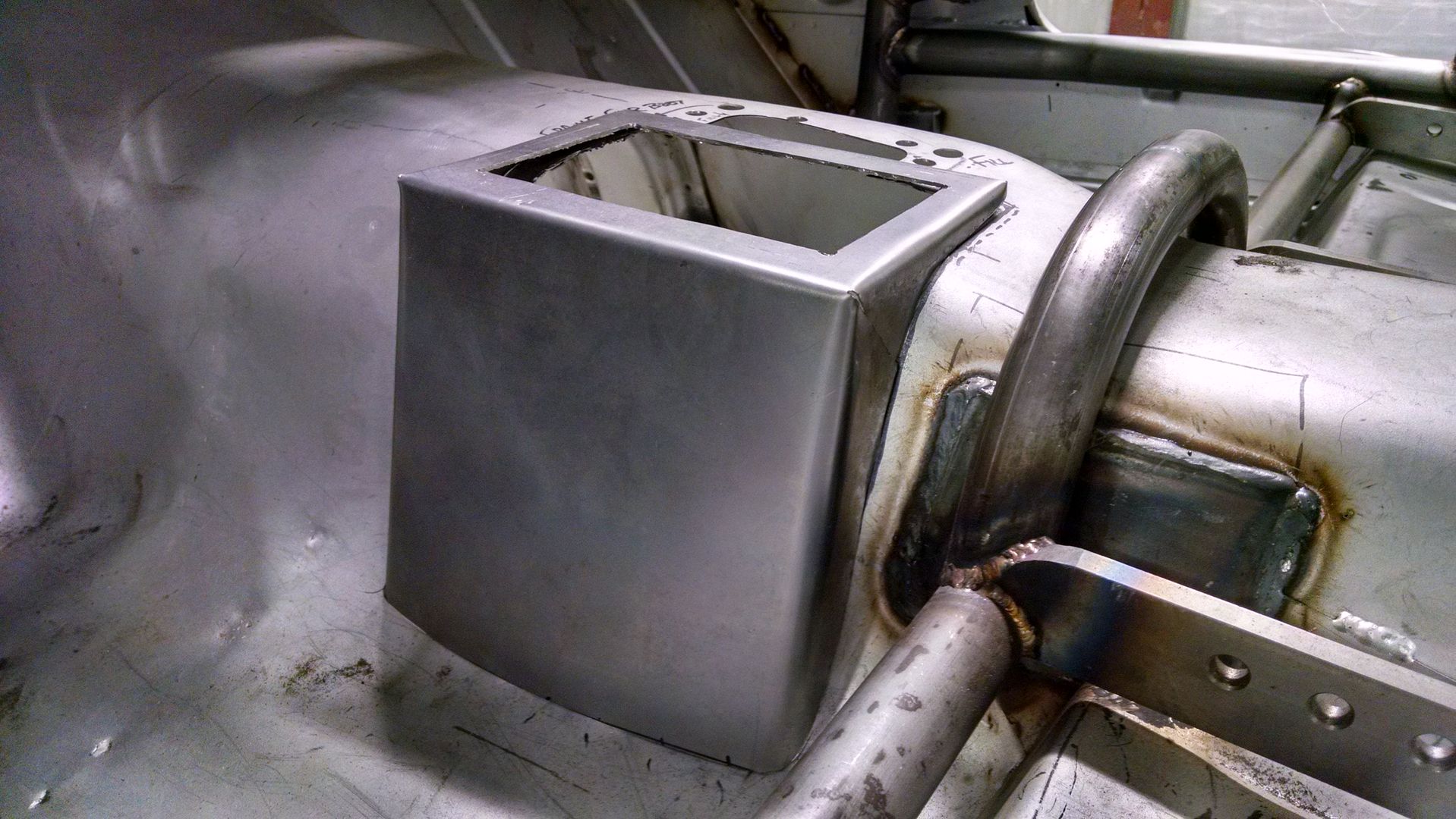
    Finally got around to translating the cardboard shifter box-out into metal today. After tweaking the template to make it fit snug against the floorpan, I cut it at a 45* angle at the upper outside corners and laid it flat on some sheet metal. A little cutting and bending and I have this - complete with just two joints on the piece to weld, then weld it to the floor. I made it out of thicker metal than was necessary, just to add back in the rigidity that I lost by cutting such a gaping hole in a brand new floor.

    Later,
    Chris

    "There are no more monsters to fear, and so, we have to build our own."
    Mk3.1 #7074

  22. #102
    Senior Member AC Bill's Avatar
    Join Date
    Feb 2011
    Location
    Vancouver Island BC Canada
    Posts
    1,888
    Post Thanks / Like
    Is there any chance that you eventually may need to access any of the shifter bolts or screws, as are visible on the lower area of the case? If so, maybe designing the cover to be removable would be helpful.

  23. #103
    Out Drivin' Gumball's Avatar
    Join Date
    Feb 2011
    Location
    Blackberry Township, IL
    Posts
    2,653
    Post Thanks / Like
    Did a final fit with the transmission to ensure that the shifter is in the right spot in relation to the new boxed out section on the tunnel. I also did a little "massaging" of the tunnel to provide extra clearance for the finned top cover and the return line for the trans cooler - simply heated the area up with an oxy/acet torch and used a dolly to give it a nice subtle bump-out.

    Before doing this final fitting, I also assembled the headers in place to make sure that the engine was properly located, since I have adjustable motor mounts.

    Very happy with the final fit, so now on to other sheet metal work.

    Later,
    Chris

    "There are no more monsters to fear, and so, we have to build our own."
    Mk3.1 #7074

  24. #104
    Out Drivin' Gumball's Avatar
    Join Date
    Feb 2011
    Location
    Blackberry Township, IL
    Posts
    2,653
    Post Thanks / Like
    Rolled the car on its side this past weekend and finished the stitch welding on the undercarriage seams. Still have to climb inside and tackle a few seams there, particularly in the rear upper structure of the car that ties the two sides together, but it's getting to the point where I only have a little more welding left - finally.


    Later,
    Chris

    "There are no more monsters to fear, and so, we have to build our own."
    Mk3.1 #7074

  25. #105
    Out Drivin' Gumball's Avatar
    Join Date
    Feb 2011
    Location
    Blackberry Township, IL
    Posts
    2,653
    Post Thanks / Like
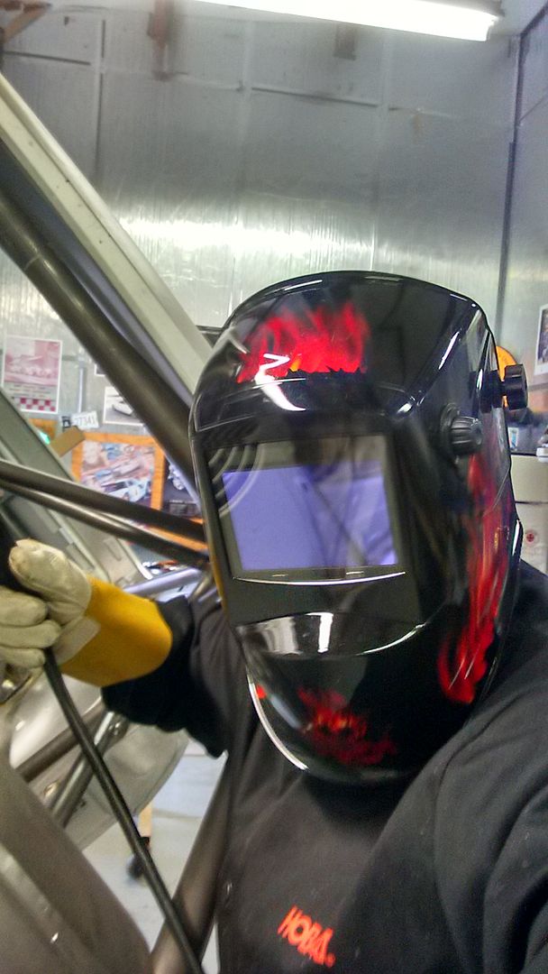
    Welding fun....

    Later,
    Chris

    "There are no more monsters to fear, and so, we have to build our own."
    Mk3.1 #7074

  26. #106
    Junior Member
    Join Date
    Apr 2017
    Posts
    1
    Post Thanks / Like
    Those frame connectors look great. What tubing size did you use and did you have them bent to any specific angles ? I have looked at doing something similar with straight tubing and it is offset from the rear frame rail by a couple of inches.

  27. #107
    Out Drivin' Gumball's Avatar
    Join Date
    Feb 2011
    Location
    Blackberry Township, IL
    Posts
    2,653
    Post Thanks / Like
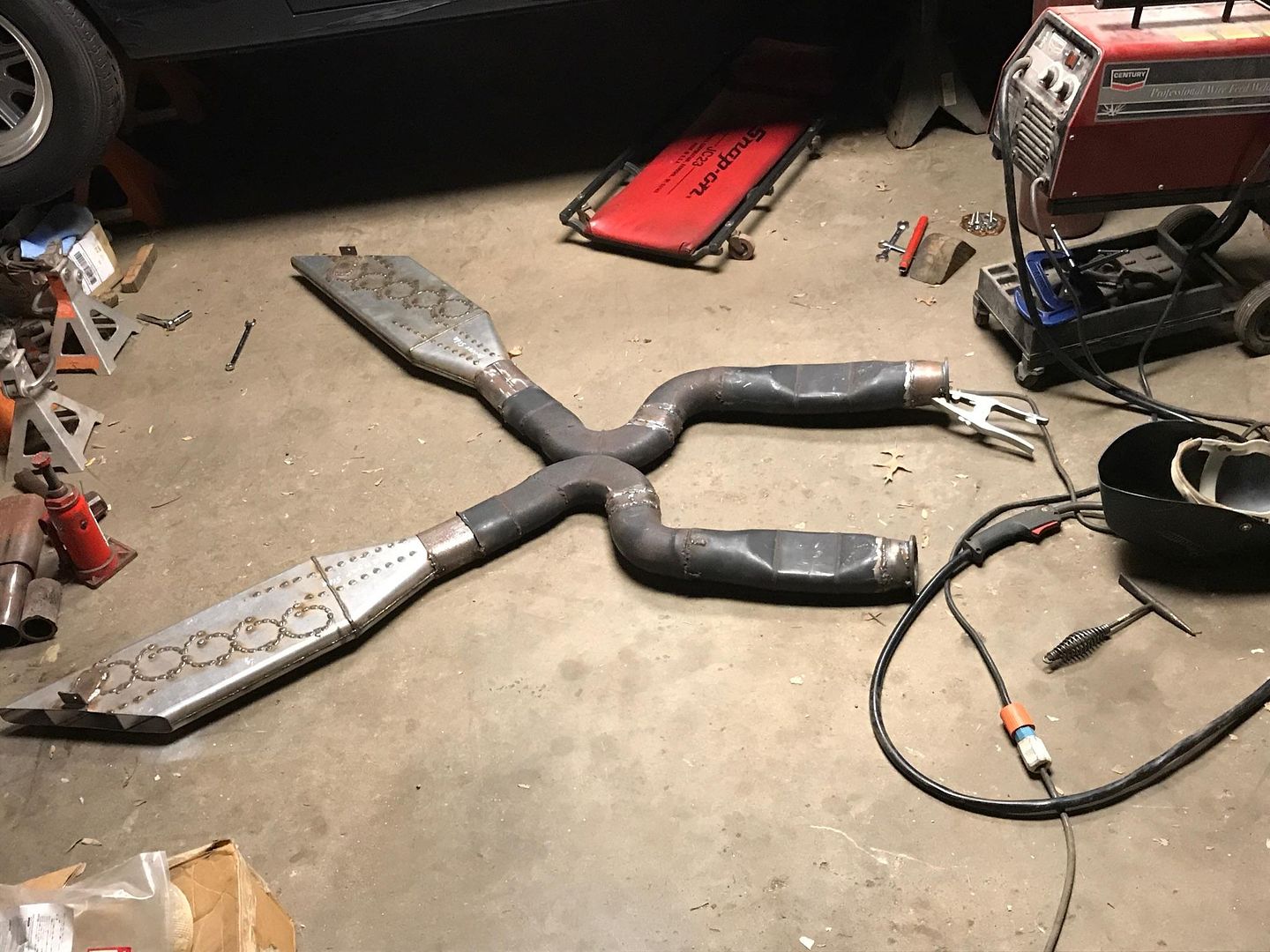
    Finally decided on my exhaust - this is a mock-up of a friend's before we welded it up, but mine will be the same. It's a Dr. Gas system using oval pipe and "boom tube" mufflers. I'm thinking that I'll probably only use one muffler exiting to the passenger side with two tubes coming into it from the "X" pipe, but I'm waiting for feedback from the manufacturer on flow rates before making up my mind.

    Sort of goofy looking, though, like it fell off the car and was run over. The boom tubes are only about 1 1/4" thick and sound incredible.

    Later,
    Chris

    "There are no more monsters to fear, and so, we have to build our own."
    Mk3.1 #7074

  28. #108
    Senior Member
    Join Date
    Oct 2016
    Location
    Palm Bay FL
    Posts
    110
    Post Thanks / Like
    This has to be one of the most awesome builds I have ever seen!

  29. #109
    Administrator David Hodgkins's Avatar
    Join Date
    Feb 2011
    Location
    Corona del Mar, CA
    Posts
    6,132
    Post Thanks / Like
    Blog Entries
    7
    Amazing talent.

    I gotta learn how to weld...


    FFR 5369 Pin Drive, IRS, Trigos, Torsen, Wilwoods, FMS BOSS 302 "B" cam , Mass-flo. CA SB100 (SPCN) Registered
    Delivered 4/23/06. "Finished" 4/2012 (still not done!)


  30. #110
    Jazzman's Avatar
    Join Date
    Jan 2014
    Location
    Scottsdale, AZ
    Posts
    1,166
    Post Thanks / Like
    Hey, Gumball, it's been months!! We need updates, photos, info!!! Come on, feed our addiction!! What's been going on?
    Jazzman

    MKIV #8745 "Flip Top" Roadster, Custom Tilt front, Coyote Engine, Tremec TKO600, Custom Interior. Best of Show winner, Huntington Beach Cruise In 2018.

    1967 Ford Mustang Coupe build thread updated 1/22/2021

    Roadster Frame Dolly Plan

  31. #111
    Out Drivin' Gumball's Avatar
    Join Date
    Feb 2011
    Location
    Blackberry Township, IL
    Posts
    2,653
    Post Thanks / Like
    Lots more stitch welding - that part is pretty much done - and I'm chipping away at the last few sheet metal to-dos on the list. Hopefully, it'll go to media blast for clean-up this fall and come back in some nice, original looking red oxide two-part epoxy sealer.

    Life's been in the way for the past year or so, what with work, house projects, driving the FFR, picking up a new GT350R, fixing Mrs. Gumball's '67 Camaro (seems to be running better than ever, finally), and other family stuff, so the Rustang has sort of moved to the back burner.

    Hope to have more to report soon, though!!!!
    Later,
    Chris

    "There are no more monsters to fear, and so, we have to build our own."
    Mk3.1 #7074

  32. #112
    Jazzman's Avatar
    Join Date
    Jan 2014
    Location
    Scottsdale, AZ
    Posts
    1,166
    Post Thanks / Like
    Thanks for the update Gumball. I saw your new GT350R (Gorgeous!!) Glad the Camero is running well. These old ones can be temperamental!! I understand family taking priority, as they should. Post when you can. Know that this thread has at least one fan!!

    It will be at least this fall before my Mustang is ready for media blasting, but that is something I am also looking forward to.
    Jazzman

    MKIV #8745 "Flip Top" Roadster, Custom Tilt front, Coyote Engine, Tremec TKO600, Custom Interior. Best of Show winner, Huntington Beach Cruise In 2018.

    1967 Ford Mustang Coupe build thread updated 1/22/2021

    Roadster Frame Dolly Plan

  33. #113
    Senior Member
    Join Date
    Jun 2013
    Location
    Bowling Green, KY
    Posts
    1,382
    Post Thanks / Like
    What a nice build.

  34. #114
    Out Drivin' Gumball's Avatar
    Join Date
    Feb 2011
    Location
    Blackberry Township, IL
    Posts
    2,653
    Post Thanks / Like
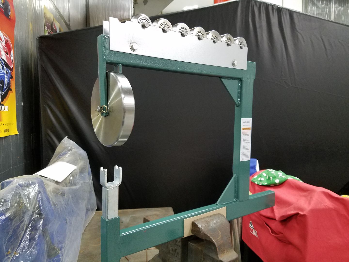
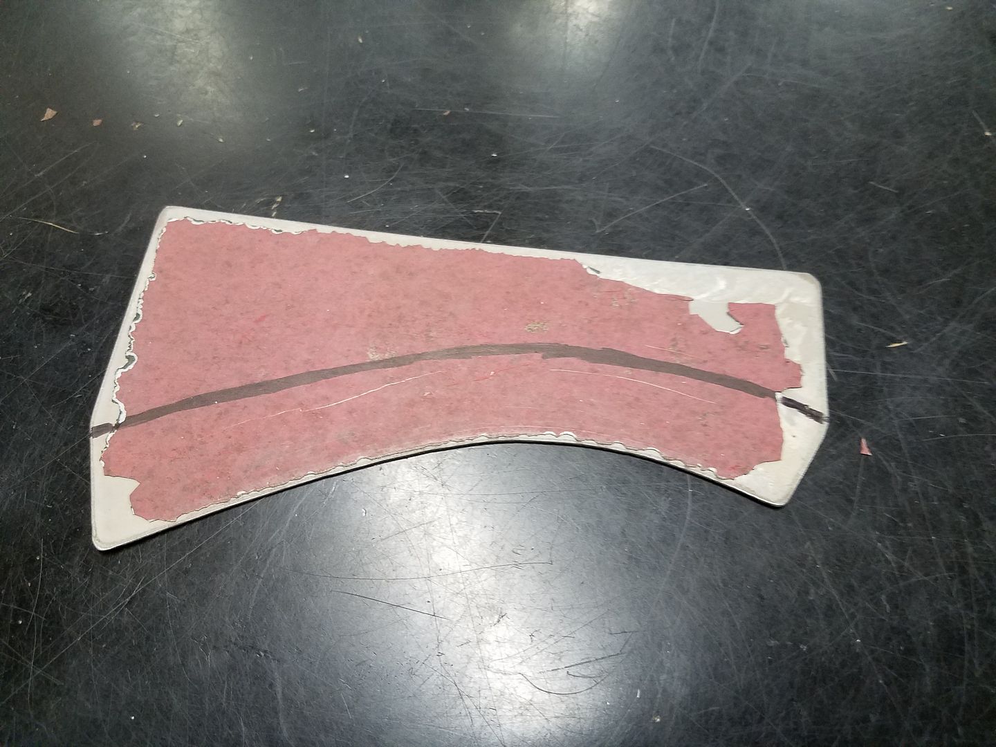
    Projects like this always serve as a good source of reasons to buy new tools and learn new skills. I really enjoyed the bodywork phase of my FFR build, but working with fiberglass is so different (and more forgiving) than working with metal. Since I'm making a bunch of small panels to cover openings in the rear bulkhead, and some of those will have to follow compound curves, I decided to pick up a small hobby-size english wheel.


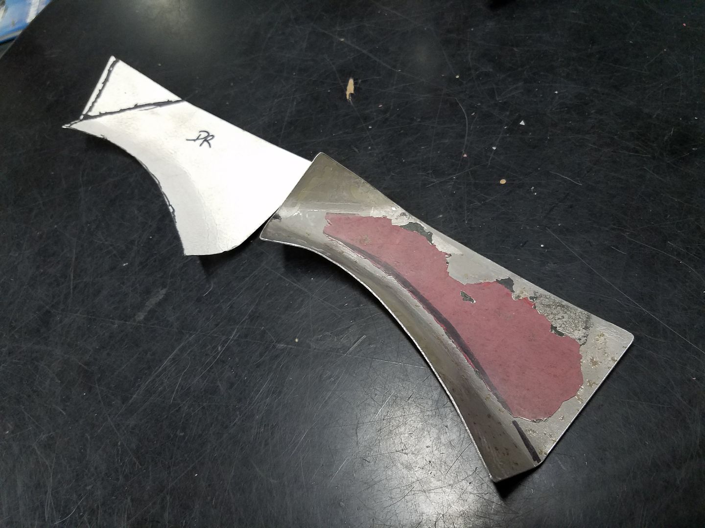
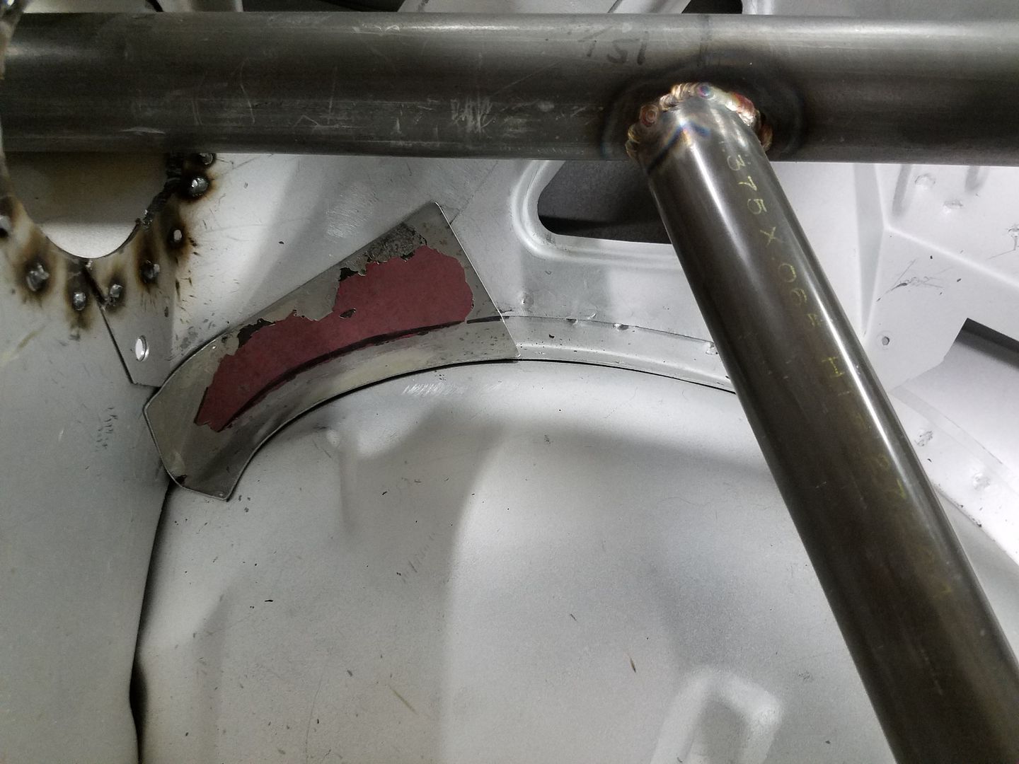
    My first project with this new tool was to make a couple of small covers that will go over a large gap in the rear bulkhead where it meets the inner wheel housings. I saved a bunch of non-rusted, galvanized metal from the body shell when it was reconstructed for just this purpose, so pardon the layers of paint built-up on the example in the photos.

    I began with a flat piece of steel that I cut to shape based on a cardboard template.....


    Then, using the cardboard template that was bent into the proper form, I used the english wheel to shape the lip that would sit on the inner wheel house (I also used a brake, rounded body hammer and shot bag, and pliers to get the rest of the curves just-so.....


    And here is the panel in place, just a little more trimming and shaping to the corners and it'll be ready to be welded in place.....

    Later,
    Chris

    "There are no more monsters to fear, and so, we have to build our own."
    Mk3.1 #7074

  35. #115
    Jazzman's Avatar
    Join Date
    Jan 2014
    Location
    Scottsdale, AZ
    Posts
    1,166
    Post Thanks / Like
    Hey Gumball, whatever happened with this project? It looked interesting. (Perhaps because of my own interest in Mustangs!!)

    Jazzman
    Jazzman

    MKIV #8745 "Flip Top" Roadster, Custom Tilt front, Coyote Engine, Tremec TKO600, Custom Interior. Best of Show winner, Huntington Beach Cruise In 2018.

    1967 Ford Mustang Coupe build thread updated 1/22/2021

    Roadster Frame Dolly Plan

  36. #116
    Out Drivin' Gumball's Avatar
    Join Date
    Feb 2011
    Location
    Blackberry Township, IL
    Posts
    2,653
    Post Thanks / Like
    Hey Jazz - and everyone else who may be interested in an update.....

    I finished the metal work on the Rustang build in the Spring of '19 and sold it last summer to a guy who was going to do the body/paint and mechanical assembly. It was just a matter of too much going on at the time, as well as changes in focus of my car hobby. I guess in hindsight, that was sort of a good decision given what has happened this year with vintage race schedules and events.

    But, after a year with little to no work to do around the shop, I picked up the '73 Z28 that is highlighted in the other thread, so please follow along on that build as it goes from a one-owner, survivor drag car to a long-haul capable pro-touring machine.
    Later,
    Chris

    "There are no more monsters to fear, and so, we have to build our own."
    Mk3.1 #7074

  37. #117
    Jazzman's Avatar
    Join Date
    Jan 2014
    Location
    Scottsdale, AZ
    Posts
    1,166
    Post Thanks / Like
    I wondered if that might have been the case. You did amazing work on the Rustang. I am sure the buyer got far more car than he paid for! We will look forward to updates on the Z28! All the best to you and yours!!
    Jazzman

    MKIV #8745 "Flip Top" Roadster, Custom Tilt front, Coyote Engine, Tremec TKO600, Custom Interior. Best of Show winner, Huntington Beach Cruise In 2018.

    1967 Ford Mustang Coupe build thread updated 1/22/2021

    Roadster Frame Dolly Plan

Page 3 of 3 FirstFirst 123

Posting Permissions

  • You may not post new threads
  • You may not post replies
  • You may not post attachments
  • You may not edit your posts
  •  

Julio Car Custom

Visit our community sponsor