-
03-03-2021, 10:05 PM
#121
Senior Member

Hinges and Doors
OK, I lied. Had some time before we drive away so decided to dive into the doors. Won’t get too serious until the body is mounted and I actually start fitting them. Which by all accounts is interesting. We’ll see. First up was modifying the provided hinges. Have read some accounts about this as well. Not sure exactly what unobtainium they’re made from. But not very friendly material. I followed the directions for the most part. Appreciated that FF provides templates. Cut the one side using the Milwaukee portable band saw mentioned before. Slow going but worked fine and cleaned the edges on my disk sander. Then drilled all the 1/8” holes. Worked with lots of cutting oil. Enlarging them and tapping the one hole in each with the kit provided tap also went OK. Again with lots of cutting oil. My challenge was with the very large countersinks. I didn’t have any that big, so picked up a 3/4" Ryobi high speed steel one at Home Depot. Only thing I could find quickly and locally. Worked OK for a while, but then just wouldn’t cut any more. Even watching the speed and feed rate, and again lots of cutting oil, it lost the battle with the hinge material. Tried sharpening it but didn’t help. Shopped around (McMaster, etc.) to see if there were better options. There are, but many times more expensive than the $10 Ryobi pieces. So back to HD, took their last two, and was able to complete but pretty much doing those in too. Kind of an expensive exercise but still cheaper (and faster) than ordering up something better. I don’t know how anyone would do these without at least a drill press. Wouldn’t be fun at all.

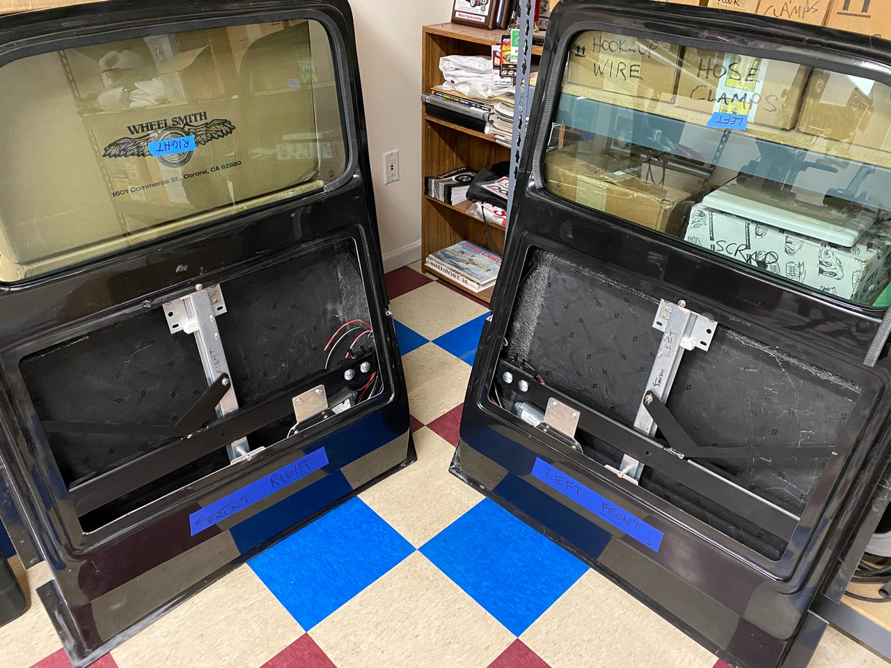
Then onto the doors. Dug out the frames and related parts and found they wouldn’t fit through the opening without some trimming to the opening. The doors in general are cut decently. But the opening was irregular. I hate making fiberglass dust in my shop. But fortunately, it was 50 degrees outside today. So out on the drive and cut and cleaned up the openings and overall a bit. With that started mocking up how the pieces go into the doors. Again, Factory Five provides templates for the hinges and latch. Nice touch. I marked all the locations but haven’t cut anything yet. Want to double check against the locations on the frame. That’s about as far as I got.

But leaves me with some questions for other truck builders who have moved past this part.
1. Did you find the hinge and latch templates were accurate? I’m a measure twice (at least…) and cut once kind of builder and really hate having to make repairs when I mess up.
2. With the inner frame set into the intended locations, there are some gaps between the frame and where it meets the inside of the door shell. Especially on the hinge sides, where the hinges are on the outside against the fiberglass. I would expect a tight fit or they’ll starting bending things when tightened. I cleaned up the inner fiberglass as much as possible. But it’s just not perfectly flat. I’m thinking of bedding the frame ends in HSRF when finally installed to fill the gaps. Your experience or suggestion?
3. Finally, is there any reason I can’t permanently mount the frames now? Once I confirm the right locations? It looks like everything else that needs to be added (door handles, power windows, etc.) can be installed with the frame in place. What do you think?
On the parts front, still waiting for my power brake system. Back and forth several times with the supplier this week and frankly I’m running out of patience. (Not a forum vendor or a company I’ve seen anyone else mention. So no worries there.) They’re still waiting on the MC from Wilwood. They’re main response this week is I can cancel the order if I want. I’m going to wait until we’re back home on the 15th. If no progress, going to look for plan B. It’s a hard time I know. But that MC is available in multiple places. Summit, Amazon, Speedway, etc. Even offered to send them one for a credit. But they insist on getting it direct from Wilwood.
Onward.
Last edited by edwardb; 03-04-2021 at 07:14 AM.
Build 1: Mk3 Roadster #5125. Sold 11/08/2014.
Build 2: Mk4 Roadster #7750. Sold 04/10/2017.
Build Thread
Build 3: Mk4 Roadster 20th Anniversary #8674. Sold 09/07/2020.
Build Thread and
Video.
Build 4: Gen 3 Type 65 Coupe #59. Gen 3 Coyote. Legal 03/04/2020.
Build Thread and
Video
Build 5: 35 Hot Rod Truck #138. LS3 and 4L65E auto. Rcvd 01/05/2021. Legal 04/20/2023.
Build Thread. Sold 11/9/2023.
-
Post Thanks / Like - 0 Thanks, 1 Likes
-
03-04-2021, 07:13 AM
#122
PLATNUM Supporting Member


1. the templates get you pretty close. But you will need to possibly modify some stuff. I had to modify the chassis frame brackets to get the proper door alignment.
2. you will need to do what you feel best in this area.
3. you can permanently install the frames. However the doors are IMO the most difficult part of the truck kit. It will test your patience for sure.
https://thefactoryfiveforum.com/show...Hot-Rod-Pickup
Last edited by wallace18; 03-04-2021 at 07:17 AM.
16+ FFR kits and counting!
-
Post Thanks / Like - 1 Thanks, 2 Likes
-
03-04-2021, 08:16 AM
#123

Originally Posted by
edwardb

But leaves me with some questions for other truck builders who have moved past this part.
1. Did you find the hinge and latch templates were accurate? I’m a measure twice (at least…) and cut once kind of builder and really hate having to make repairs when I mess up.
Yes, they are excellent, With your patience and skill they will work out well.
2. With the inner frame set into the intended locations, there are some gaps between the frame and where it meets the inside of the door shell. Especially on the hinge sides, where the hinges are on the outside against the fiberglass. I would expect a tight fit or they’ll starting bending things when tightened. I cleaned up the inner fiberglass as much as possible. But it’s just not perfectly flat. I’m thinking of bedding the frame ends in HSRF when finally installed to fill the gaps. Your experience or suggestion? Agreed, This is tough, I have had to trim the steel frame to allow it to sit flush as well as clean up the inside of the door, if they don't sit flat together you are correct, they will make things get funky when tightened.
3. Finally, is there any reason I can’t permanently mount the frames now? Once I confirm the right locations? It looks like everything else that needs to be added (door handles, power windows, etc.) can be installed with the frame in place. What do you think? you can, however you will likely want to remove the hinges for paint and body work, and these hold the frames in. I have done it both ways, its worth the effort(IMHO) to remove the frames for paint and body work, You have to be careful with reassembly, but that is not beyond your skill set.
On the parts front, still waiting for my power brake system. Back and forth several times with the supplier this week and frankly I’m running out of patience. (Not a forum vendor or a company I’ve seen anyone else mention. So no worries there.) They’re still waiting on the MC from Wilwood. They’re main response this week is I can cancel the order if I want. I’m going to wait until we’re back home on the 15th. If no progress, going to look for plan B. It’s a hard time I know. But that MC is available in multiple places. Summit, Amazon, Speedway, etc. Even offered to send them one for a credit. But they insist on getting it direct from Wilwood.
Onward.
Responses Imbedded.
-
Post Thanks / Like - 1 Thanks, 2 Likes
-
03-04-2021, 12:13 PM
#124
East Coast Speed Machines

FFR 1879, Blown DSS 306,REDLINE management, VeryCoolParts Tuned 460RWHP
FFR 818S, The Flash, Chassis #5, 2.0L, LSD, Electromotive TEC-S, VCP Tuned, 278RWHP 265 RWTQ
FFR 6651, Green Lantern, 408W Crate, Hellion 66mm Turbo, JGS Waste gate / Blowoff valve, Tec-GT management, VCP Tuned, 575 RWHP, 690 RWTQ
FFR 8335, Black Mamba, 289 FIA CSX 2001 tribute car, 347, 48 IDA webers, VCP Tuned, 311 RWHP 386 RWTQ, 3-link, Trigo's
FFR 0004, Gen 3 , Hawk Coupe, Coyote twin turbo, 683 RWHP 559 RWTQ, IRS, VCP Tuned. "not too shabby"
US ARMY Maintenance Test Pilot (CW4 Retired)
-
Post Thanks / Like - 1 Thanks, 1 Likes
-
03-04-2021, 04:21 PM
#125
Senior Member
Thanks for the feedback guys. Much appreciated. Have a good idea what to do now.
Build 1: Mk3 Roadster #5125. Sold 11/08/2014.
Build 2: Mk4 Roadster #7750. Sold 04/10/2017.
Build Thread
Build 3: Mk4 Roadster 20th Anniversary #8674. Sold 09/07/2020.
Build Thread and
Video.
Build 4: Gen 3 Type 65 Coupe #59. Gen 3 Coyote. Legal 03/04/2020.
Build Thread and
Video
Build 5: 35 Hot Rod Truck #138. LS3 and 4L65E auto. Rcvd 01/05/2021. Legal 04/20/2023.
Build Thread. Sold 11/9/2023.
-
03-04-2021, 08:46 PM
#126
Senior Member

Yes the doors are the most challenging part of the build. I powder coated my frames before the assembly process. The frames are bent just I smidge to far to get a flat tight fit in the hinge pocket area I have truck 16 and mine were like that as well. . Once the door is hung on the truck that’s where all the monkeying begins. I had to twist the rear of the door and retighten the crash beam bolts and the rear pocket by the latch bolts to get the twist to hold the door where I wanted it.
I’m sure you will have now problem figuring it out. Rob
FFR 35 p/u # 0016 Dart 347 TKO 600
-
03-11-2021, 04:31 PM
#127
Sharp set of wheels, been following your build and it looks awesome. You do great work!!
-
Post Thanks / Like - 1 Thanks, 1 Likes
-
03-16-2021, 10:01 PM
#128
Senior Member
Back At It LS Frontrunner
Arrived back home from our trip to Texas. 3,000+ miles. Went by the Embassy in San Marcos on our way in and out of town. Looked pretty quiet without all Cobras that will be there in a couple weeks. For those that will attend, have a great time. We made it there two years ago. But timing just didn't work this year. Had a nice family visit and was great meeting our fourth grandchild for the first time. Special memories.
While gone, Vintage Air shipped my frontrunner setup. So was waiting for me when we got back. Still nothing on my power brake setup. I’m working on an alternate plan and expect to make a decision this week if the supplier doesn't come through. Finished installing the frontrunner setup today. It wasn’t cheap. But I’m very pleased with the quality, the instructions, how everything fit, and now the final product. The components are all high quality including a nice 170 amp alternator, Sanden A/C compressor, an ATI Super Damper harmonic balancer, nice billet aluminum mounts for everything, and even ARP hardware. The biggest challenge was changing out the stock balancer with the ATI piece. None of the tool rental places had a puller for an LS style balancer. So Amazon to the rescue even though I probably (hopefully…) won’t use it again. Also picked up a flywheel lock. Cheap and not sure I could have accomplished the swap without it. Followed the directions exactly and everything worked out. It's a good pull and right at my limit to get the retaining bolt for the balancer torqued. But done. I still have to get a different thermostat and thermostat housing. Other than that, ready to go. Both length and width worked out fine. It’s going into fit in the chassis and body just fine. Here are some pics. Will go back to working on the doors for now.


Last edited by edwardb; 03-17-2021 at 06:05 AM.
Build 1: Mk3 Roadster #5125. Sold 11/08/2014.
Build 2: Mk4 Roadster #7750. Sold 04/10/2017.
Build Thread
Build 3: Mk4 Roadster 20th Anniversary #8674. Sold 09/07/2020.
Build Thread and
Video.
Build 4: Gen 3 Type 65 Coupe #59. Gen 3 Coyote. Legal 03/04/2020.
Build Thread and
Video
Build 5: 35 Hot Rod Truck #138. LS3 and 4L65E auto. Rcvd 01/05/2021. Legal 04/20/2023.
Build Thread. Sold 11/9/2023.
-
Post Thanks / Like - 0 Thanks, 1 Likes
-
03-31-2021, 08:24 PM
#129
Senior Member
Lots Going On
Finally time for another update. First parts. It’s been a few weeks since I checked in with Factory Five and received prompt responses. I’m still missing eight items. Couple are now in stock and a couple should be soon. So hopefully I’ll be getting those. Several are still without promises. Confirmed spindles slipped to late May or early June, as I saw in at least one other build thread. The circumstances are different and hopefully not as bad. But reminds me a little of the wheel challenge of a few years ago. Good news is that got resolved, everyone got their wheels, and it’s a distant memory. Looking forward to that with the spindles like many others. At this point nothing is holding me up and won’t for a while.
The other part issue that I’ve been reporting and following up closely is my power brake setup. I’ll spare the details. The good news is today I finally received a shipment and we’re making progress. But there are still issues. I’ve got another direction that shouldn’t take as long if this doesn’t get resolved. Let’s just say I’ve learned how credit card disputes work. First time for me. To be continued.
As far as real work, several areas to report on. As mentioned in a previous update, I purchased a Dakota Digital CRC-1000-2 GM LS drive-by-wire cruise control kit. This version uses an HND-2 dash mounted controller. To be honest, I wasn’t all that happy with the controller when received. Buttons don't have a great feel and the appearance is just not what I'm looking for. I really wanted the HND-3 controller that mounts on the end of the turn signal. Like many DD’s. But as I stated in a previous update, didn’t like that it would mean a wire down the outside of my Ididit steering column. Turns out I was wrong. Upon further review, the cable is inside the steering column and completely hidden. So I ordered and received the HND-3 controller. Took some major fiddling but was able to snake the cable down inside next to the main ribbon cable. Would have been easier to take the GM style turn signal assembly out. But it uses a snap ring that takes a special tool to remove. Managed to get it done without taking anything apart. So happy with that change. The only surprise is that after talking to Dakota Digital, turns out I needed a different interface cable between the controller and the cruise control module. Part number 394207 ordered and received. It’s more than just swapping pins or I would have done that. It also has an inline inverter. So I should be all set. But sure would have been easier (and cheaper) if I’d have selected the right kit version to start with. Since this picture was taken, pulled a little slack in the cable to keep it away from moving parts and tacked it down with a blob of silicone RTV.

I started working on the cold air intake for the LS3. For my Gen 2 Coyote, I used Spectre parts. For my Gen 3 Coyote, I used Treadstone Performance parts. Both listed in the Factory Five Coyote instructions. Several builders have reported issues getting parts from Treadstone. But reported good results from Performance MRP. So placed an order with them for the 4” MAF housing (with air straightener) and a 90-degree silicone elbow. Air cleaner I’ll figure out later. Still unsure of the exact space available. Shipped the same day and was here in two days. The MAF housing is perfect. Unfortunately, I didn’t check the length of the legs on the 90-degree elbow close enough. Not long enough to clear the LS3 front accessory drive. So back the elbow went. They don’t have any other options. But ones that will work are available elsewhere.

I previously mentioned starting work on the doors. Spent a lot of time since then. Nearly every truck build thread has some comments about them. They are a lot of work and can be challenging. The kit comes with a 2-piece frame that mounts inside the door shell. One side against the back and holds the bear claw style latches. The other side on the front holds the two hinges. The cross piece holds the power window mechanism. The kit has nice templates for where to mount on each side. But the challenge I found is that the flats on the frame didn’t always fit tight against the inside of the door skins. Which they need to for maximum strength and to prevent distorting the fiberglass in the case of the hinges. With some sanding and correcting the angle on the metal pieces on the latch sides, I was able to get acceptable. But neither hinge side was great. Especially one even after I removed some metal from the frame and cut the glass a bit. I’m positive not many builders will agree with what I did next (in fact maybe no one…) but I decided to bed the frame sides in 3M HSRF. That filled the gaps around the hinge and latch mounting points, made them rock solid, and all is good. The bad part is those frames are not coming out again. Won't describe everything I did, but I spent a whole bunch of time making sure they were in the exact right position including checking the fit against the body repeatedly. Which looks pretty good at this stage. Also was really careful not to put any stress or bends in the door shells. Wouldn't be easy, but was careful nonetheless. Put some rattle can satin black chassis paint on the bare metal frames before installing. Also put two panels of Second Skin Damplifier Pro sound deadening material on the doors. I’m happy with how this all turned out. But it’s a pretty big gamble. It will be some months before I find out if I made the right decision.


Next up I decided I could get the exhaust system completely sorted out then remove as one piece each side and be ready to finally install later. Also I wanted to get the exact positions in advance of routing fuel lines, brake lines, electrical harnesses, transmission cooling lines, e-brake cables, etc. After my initial mock-up, had some questions so posted a separate thread. https://thefactoryfiveforum.com/show...tion-Questions. Received some excellent feedback and now have them installed. I ended up not putting hangers on each side of the mufflers as the instructions show. I think overkill plus the mounting is a little clunky IMO. Rather just one large one on each side at the back. I used the Pypes Exhaust HVH11S suggested by Gary in that linked thread along with the kit rubber lined mounts. Bent those to fit over the frame and held in place with 5/16” nutserts. It’s super solid with just the right amount of dampening. The main departure I made from the instructions was to rotate the mufflers so that the exits are on the inside vs. the outside. Based on other build pictures, seems the LS setup is a bit wider than others. With the exits on the outside, the last tubes ran into the rear LCA mounts. Inside fits perfectly. I always enjoy working with my lift (except when it keeps bumping into my head…) but especially for getting this exhaust system figured out and installed. Sorry for the somewhat crummy pictures. But not going to apologize for the sun shining through the windows.


Hope to start working on the power brake installation and then all the behind the dash stuff. Also can do some more work on the doors doing some of the pre-work for the power windows. Meanwhile, the weather is pretty much changing and I’ve had the Coupe out twice. Local events are starting in April along with club events. Still low key and following guidelines. But great to get out. Will cut into building time, but that’s OK.
Last edited by edwardb; 04-01-2021 at 06:11 AM.
Build 1: Mk3 Roadster #5125. Sold 11/08/2014.
Build 2: Mk4 Roadster #7750. Sold 04/10/2017.
Build Thread
Build 3: Mk4 Roadster 20th Anniversary #8674. Sold 09/07/2020.
Build Thread and
Video.
Build 4: Gen 3 Type 65 Coupe #59. Gen 3 Coyote. Legal 03/04/2020.
Build Thread and
Video
Build 5: 35 Hot Rod Truck #138. LS3 and 4L65E auto. Rcvd 01/05/2021. Legal 04/20/2023.
Build Thread. Sold 11/9/2023.
-
Post Thanks / Like - 0 Thanks, 3 Likes
-
04-01-2021, 09:29 AM
#130
As for your air intake, might want to look at my thread on the subject. https://thefactoryfiveforum.com/show...intake-install
Gary
FFR Gen 2 35 truck, Barrett Jackson edition # 4, chassis # 81, 525HP LS3 & 4L75E, 8.8" 3 link.
-
04-01-2021, 11:50 AM
#131
Senior Member
Originally Posted by
House Money
Missed that post. Thanks for the heads up. I'll review further and get mine planned out. Yours looks good. I agree with using T-bolt style clamps. I had a flat bed tow of shame incident with my Coyote powered Roadster when the worm drive clamps on the intake failed. I've used the T-bolt style since. Much better.
Build 1: Mk3 Roadster #5125. Sold 11/08/2014.
Build 2: Mk4 Roadster #7750. Sold 04/10/2017.
Build Thread
Build 3: Mk4 Roadster 20th Anniversary #8674. Sold 09/07/2020.
Build Thread and
Video.
Build 4: Gen 3 Type 65 Coupe #59. Gen 3 Coyote. Legal 03/04/2020.
Build Thread and
Video
Build 5: 35 Hot Rod Truck #138. LS3 and 4L65E auto. Rcvd 01/05/2021. Legal 04/20/2023.
Build Thread. Sold 11/9/2023.
-
04-01-2021, 01:41 PM
#132
Actually, I realized that post needed to be updated, so might want to take another look.
Gary
FFR Gen 2 35 truck, Barrett Jackson edition # 4, chassis # 81, 525HP LS3 & 4L75E, 8.8" 3 link.
-
04-05-2021, 05:26 PM
#133
The Vintage Air LS Frontrunner looks clean and compact nestled in the tubular engine compartment, is that anodized black or black chrome? Which ever it is I will be researching it online.
-
04-05-2021, 05:42 PM
#134
Originally Posted by
HotrodMike
The Vintage Air LS Frontrunner looks clean and compact nestled in the tubular engine compartment, is that anodized black or black chrome? Which ever it is I will be researching it online.
You might want to take a look at the Holley set-up too. Here is a link to my post about it: https://thefactoryfiveforum.com/show...ccessory-drive
Gary
FFR Gen 2 35 truck, Barrett Jackson edition # 4, chassis # 81, 525HP LS3 & 4L75E, 8.8" 3 link.
-
04-05-2021, 09:10 PM
#135
Senior Member
Originally Posted by
HotrodMike
The Vintage Air LS Frontrunner looks clean and compact nestled in the tubular engine compartment, is that anodized black or black chrome? Which ever it is I will be researching it online.
It's anodized black. I'm happy with how everything fit. Instructions are good. Did take about 6 weeks to get after I ordered. Quality parts like the branded Sanden A/C compressor, ATI SFI balancer, ARP hardware, etc. Not saying others aren't similar. But I'm glad I went with it. Other finishes are available.
Build 1: Mk3 Roadster #5125. Sold 11/08/2014.
Build 2: Mk4 Roadster #7750. Sold 04/10/2017.
Build Thread
Build 3: Mk4 Roadster 20th Anniversary #8674. Sold 09/07/2020.
Build Thread and
Video.
Build 4: Gen 3 Type 65 Coupe #59. Gen 3 Coyote. Legal 03/04/2020.
Build Thread and
Video
Build 5: 35 Hot Rod Truck #138. LS3 and 4L65E auto. Rcvd 01/05/2021. Legal 04/20/2023.
Build Thread. Sold 11/9/2023.
-
04-08-2021, 09:29 AM
#136
Glad the MAF housing worked out, I have nothing but good to say about Performance MRP. Great product, US based, and FAST!
-
Post Thanks / Like - 1 Thanks, 1 Likes
-
04-08-2021, 09:12 PM
#137
Senior Member
Power Windows
Couple updates ago I showed work on the doors. While waiting for other parts, decided to install the power windows. First time I’ve even done anything like this. Was a learning experience and a study in patience to be honest. First the good news. Congratulations to Factory Five engineering for figuring everything out. It’s pretty amazing how it all goes together given the angles, clearances, etc. But as I found out, very little margin for error. The build manual in this case is relatively thorough and takes you through all the steps.
All the pieces and parts come with the kit. Based on the labels and instructions, from Ball’s Rod and Kustom, and are listed on their website as made in the USA. All the parts seem robust and well made. The motors and track assemblies run smooth and strong. All good. The glass is custom, with the same DOT code as the windshield and rear cab glass. Seems decent.
I won’t replay all the steps in the build manual. But here are some observations after several days at it:
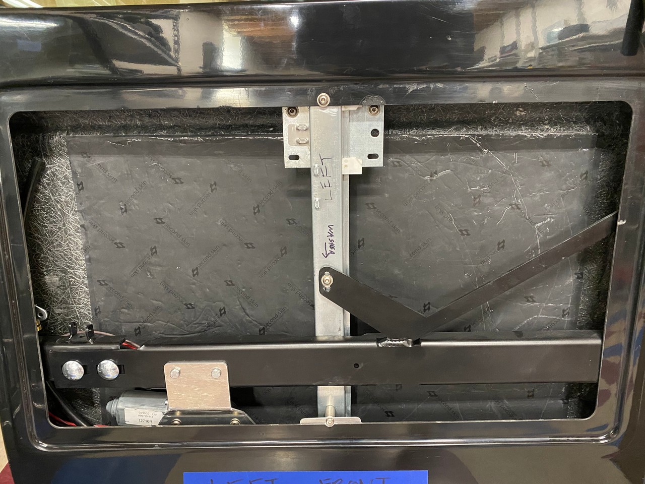
1. The lift track is held near the center by a metal bracket that’s part of the inner door frame. Then attached at the top and bottom of the fiberglass door opening. Way back when I first worked on my doors I cleaned up the perimeter of the opening and made all the sides the same width. My OCD at work. I don’t remember taking off a lot of material. But I was left with the lift track mounting points very close to the edge at both top and bottom. Didn’t want to leave it that way. So bonded a 1 x 3 inch piece of .063 aluminum at the bottom edges with a 1/4 inch overhang. Moved the top up slightly and the bottom is mainly held by the added plate.
2. It’s not explained in the manual, but the glass has to be slid into place first. Front angled corner through the window opening and down into the lower part of the door. Then it can be pivoted and raised up into position. Then the lift mechanism. Track first under the frame toward the hinge side of the door. Then the lift motor under the frame at the center cutout. Down and back up with the mount bracket on top of the frame. Removal in both cases is just the opposite. The above might be obvious to some. But it wasn’t for me. I lost track of how many times I had the pieces in and out. A bunch.
3. Also not explained in the manual, but once you have the lift track and lift motor positioned, you have to drill holes in the door frame for the mount. They are not pre-drilled. I can see why because there could be some variation. No big deal, but it’s relatively thick steel you get to drill through.
4. I found the angle of the lift track must be very carefully set. The manual describes that it needs to be at a slight angle so the glass runs evenly in the frame. But it also has to be at just the right angle and distance to clear the door latch inside. It ends up very close.
5. The kit provides felted weatherstrip for the inside of the window frame, and what’s interestingly called “cat head weatherstrip” for the outside. I admit it does have kind of that profile. But could have been any number of other animals. (Sorry cat lovers.) It all works pretty OK with one exception I’ll describe later. But what I did find was that while the felt lined material allows the glass to slide freely the cat head material does not. Both are somewhat compressible, so the inclination is to cut the slot in the fiberglass window frame to compress the weatherstrip some. Be very careful. I had to cut mine twice because the first time I make it too tight. The glass would barely move. Just a little compression is all that’s needed.
6. The build manual describes installed stops at the top and bottom of the lift track. I found it only needed stops at the top. The bottom hits the limit of the mechanism with about 1/2 inch of glass still sticking out. Which is fine. Speaking of that, the lift motor and mechanism is electrically very basic. It’s either on or off. And the glass moves relatively quickly. When it hits the stops, the motor is stalled. So you need to let go of the button. It’s OK as long as you understand that. Hold onto the button with it stalled and seems you could blow a fuse or damage something. That also means there’s no express up or down like on most DD’s, although I see on Ball’s website they do sell a module that provides that function. Also means the windows are potentially dangerous like in the good old days. Watch the fingers, hands, arms, etc. and kids around them.
7. Finally, nothing is mentioned but I’m planning to put a couple drain holes in the bottom of the doors. The windows seem to seal up reasonably well. But I’d still want a pathway for water to exit and not pool in the bottom.
So with that, here are pictures. Not really much can be seen here. Just that the mechanism and windows are in and they power up and down the way you’d expect.

Now for the one remaining issue. Which is also documented in another thread by FLFrank35: https://thefactoryfiveforum.com/show...oor-window-gap. The cat head weatherstrip is supposed to be applied along the bottom inside edge. In addition to the entire outside border. Unfortunately, the gap when all is said and done on mine is 9/16” on the left door and 1/2" on the right door. That’s from the installed glass to the edge of the factory cut opening with all the other weatherstripping installed. In both cases, too wide for the supplied weatherstrip to fill. Compounding the problem a bit is the fiberglass is pretty flexible across that area. Needless to say it would have been better for this to have been left with some to trim off like every other part of the window frame. I’ve set my doors aside for now and will see what others come up with. Also keeping my eye out for some other weatherstripping that might work. It would be technically possible to build up the edge with fiberglass, cloth, HSRF, etc. But not sure that’s the best solution.
In the ongoing saga of my power brakes, I do now have mostly what I’m supposed to have. From a company I’ll never use again thank you very much. Not a forum vendor and not one I’ve ever seen mentioned. Tomorrow I’m going to start laying things out and dive into it. I’ll explain more and post some pictures when there’s something to see. In summary what I will have is vacuum power brakes. Dual master cylinder with integral reservoirs (Wilwood), proportioning valve, and hydraulic brake light switch in the engine compartment on the firewall. Tight but so far looks like it will fit. Then a brake pedal without the Wilwood pedal box on the inside. Eliminating the Wilwood pedal box gives me a little more space. Plus the right pedal ratio for power brakes. I don’t need the clutch pedal because of the auto trans obviously. I’ll have to do some cutting on the firewall frame and probably have some welding done. Welding isn’t on my resume. We’ll see what other unintended consequences this causes. Just received an email of some more POL items shipping from Factory Five. Progress.
Our early spring has allowed me to get the Coupe out several times now. Yesterday as I was going out the door for another drive, my bride said “What about me?” so along she went. Had a great cruise. Running great and A/C blowing cold. Other than being stuck behind a slow pickup truck during some of the best curves. Don’t these people have rear view mirrors? Hope to get to a Cars and Coffee this Saturday if it doesn’t rain. That time of year too. Have I mentioned how much I like that car?
Last edited by edwardb; 12-07-2022 at 02:58 PM.
Build 1: Mk3 Roadster #5125. Sold 11/08/2014.
Build 2: Mk4 Roadster #7750. Sold 04/10/2017.
Build Thread
Build 3: Mk4 Roadster 20th Anniversary #8674. Sold 09/07/2020.
Build Thread and
Video.
Build 4: Gen 3 Type 65 Coupe #59. Gen 3 Coyote. Legal 03/04/2020.
Build Thread and
Video
Build 5: 35 Hot Rod Truck #138. LS3 and 4L65E auto. Rcvd 01/05/2021. Legal 04/20/2023.
Build Thread. Sold 11/9/2023.
-
Post Thanks / Like - 1 Thanks, 2 Likes
-
04-09-2021, 05:18 AM
#138
Senior Member
Looks good your making great progress. Couple things to keep in mind.
The outside mirrors need to be installed before you set the glass for the final time with urethane because they are set behind the glass. I fabricated a small piece of metal as a backing plate to give it some rigidity to bolt to the fiberglass door.
The inner upper part of the door is flimsy for sure when you install the door trim panel it will stiffen it up however I glued a paint stick on the inside for a little more support.
The door trim panels are thick aluminum backed and are straight as an arrow and now your door has a twist in it the panel will need to be twisted to match and lay flat on the door but no big deal just a heads up on that.
You have a beautiful build going on whats your plan for the bed ?
I used a product from Smokey road rod shop . It’s a aluminum bed that looks just like wood and very easy to install with zero maintenance. Rob
FFR 35 p/u # 0016 Dart 347 TKO 600
-
04-09-2021, 05:55 AM
#139
Senior Member
Originally Posted by
Robodent
Looks good your making great progress. Couple things to keep in mind.
The outside mirrors need to be installed before you set the glass for the final time with urethane because they are set behind the glass. I fabricated a small piece of metal as a backing plate to give it some rigidity to bolt to the fiberglass door.
The inner upper part of the door is flimsy for sure when you install the door trim panel it will stiffen it up however I glued a paint stick on the inside for a little more support.
The door trim panels are thick aluminum backed and are straight as an arrow and now your door has a twist in it the panel will need to be twisted to match and lay flat on the door but no big deal just a heads up on that.
You have a beautiful build going on whats your plan for the bed ?
I used a product from Smokey road rod shop . It’s a aluminum bed that looks just like wood and very easy to install with zero maintenance. Rob
Thanks for your comments. Much appreciated. My glass isn't set and won't be until final assembly. Agree about the backing plate on the mirrors. I haven't placed them or the door handles yet. Want to wait until the doors are trimmed and fitted to get the exact locations. The window mechanism and glass all go in and out somewhat easily. As I've done many times already. Maybe Factory Five made a change on the door cards? Mine are bent to (mostly) fit to the shape of the door. Agree they will add some strength. I mentioned that in the thread I linked to. I also had thought about gluing something on the backside to stiffen it a bit. But still left with the too large gap issue which is TBD.
The aluminum bed is an interesting option. I ordered the optional wood bed with my kit. But word from Factory Five is they lost their vendor and are looking for a new one. I've already suggested they could cancel and give me a credit. There are plenty of options including this one I'll check out.
Build 1: Mk3 Roadster #5125. Sold 11/08/2014.
Build 2: Mk4 Roadster #7750. Sold 04/10/2017.
Build Thread
Build 3: Mk4 Roadster 20th Anniversary #8674. Sold 09/07/2020.
Build Thread and
Video.
Build 4: Gen 3 Type 65 Coupe #59. Gen 3 Coyote. Legal 03/04/2020.
Build Thread and
Video
Build 5: 35 Hot Rod Truck #138. LS3 and 4L65E auto. Rcvd 01/05/2021. Legal 04/20/2023.
Build Thread. Sold 11/9/2023.
-
04-10-2021, 08:09 PM
#140
Senior Member
Sneak Peak
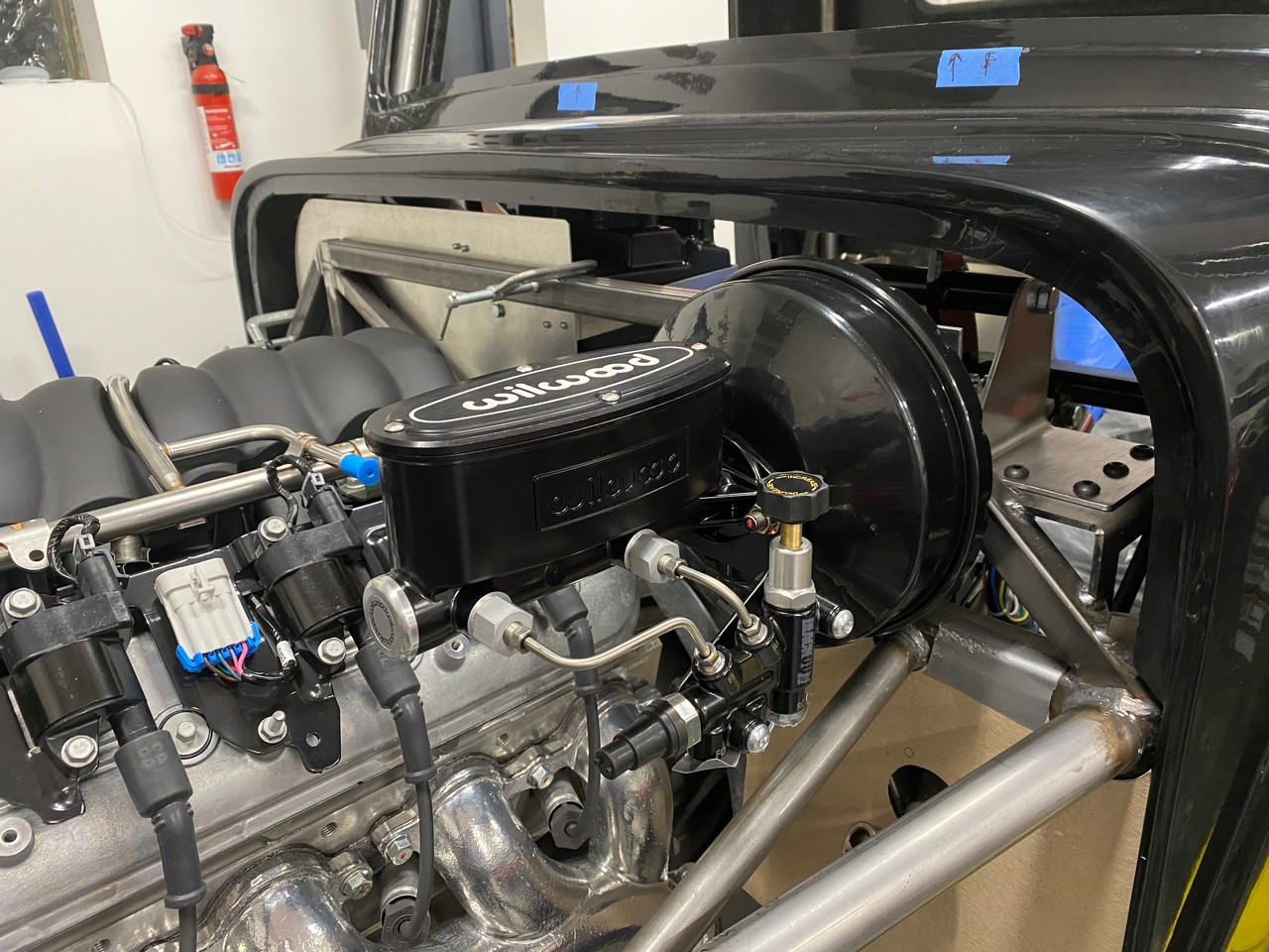
After a lot of measuring and checking, confirmed the booster and master cylinder would fit. So out came the Sawzall, air saw, angle grinder, and whatever else I could get my hands on to cut a 2-1/2" diameter hole in the frame. Also put all the Wilwood pedal box stuff up for sale. So I’m committed now. With the unit in the planned location as pictured (even with the Wilwood cover the wrong direction), clears the hood, side panel and engine on the outside. On the inside, the pedal arm just clears the steering column and mount for the Ididit column. Everything lines up and looks good. Brake pedal to accelerator spacing is very close to what it would have been with the original setup. I’ve ordered a piece of sheet steel from McMaster to make a plate for the firewall and the brackets to hold the pedal. I’ll post some pictures and provide more details when it’s more finalized. But I think this is going to work. Pretty excited about it.


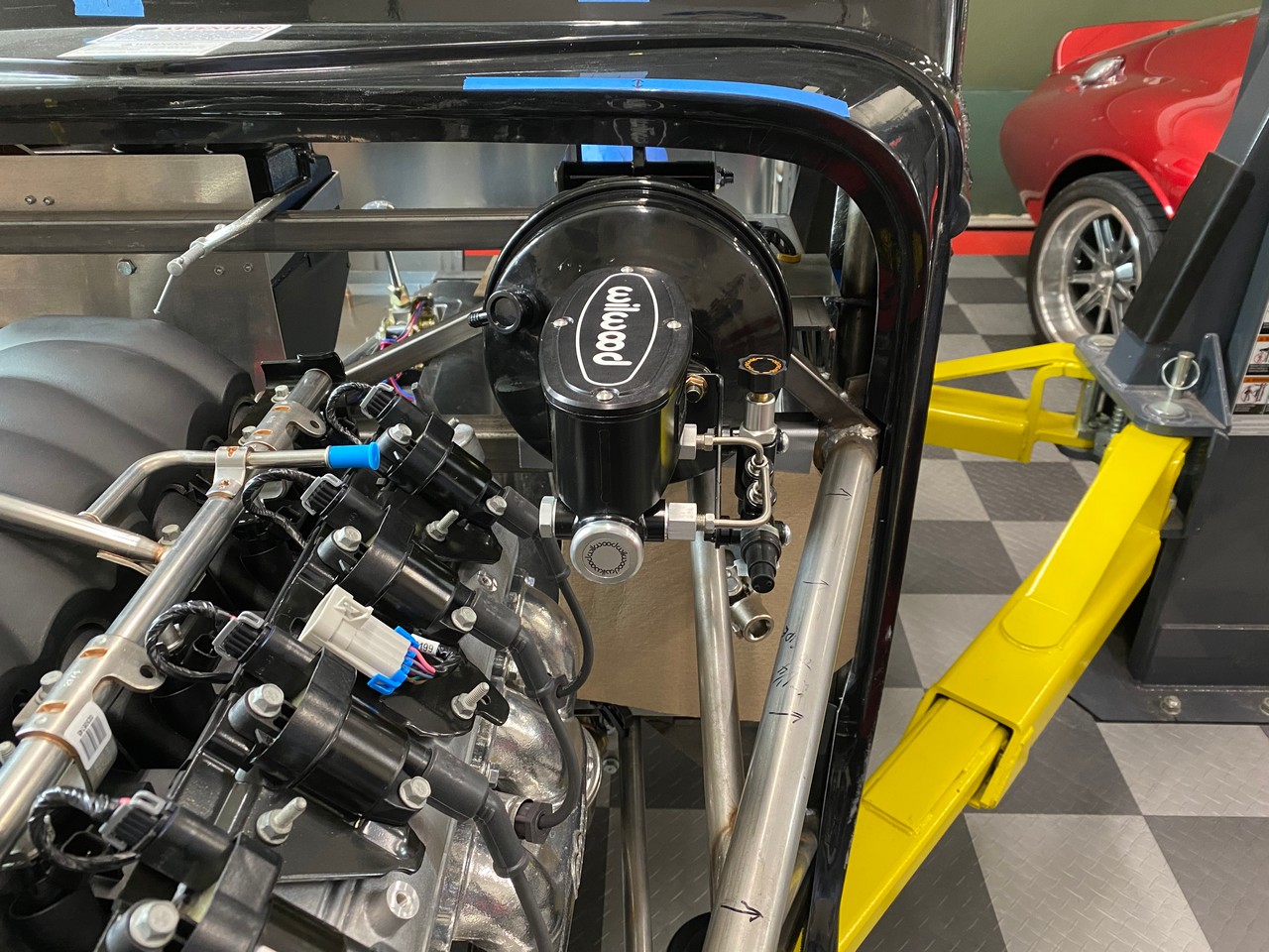
Received a POL box today from Factory Five today with three more parts. Now down to just five open. Based on the most recent update, will be a while before a couple of these are closed. But feel like the end is near. This topic gets a lot of attention here and especially it seems over on the Facebook builders group. Patience remains the order of the day and even though I’ve had to jump around a bit, really hasn’t slowed me down.
Side note. I received a few comments about my seeming need to always be bumping my head when working under the lift. Appears I’m not the only one who does that. Just to put everyone’s mind at ease (I know you were worried…) I’m now the proud owner of a Skullerz 8950 safety bump cap. I’ve got it hanging on the lift next to the controls so I don’t forget. Now just need to use it.
Last edited by edwardb; 04-11-2021 at 06:11 AM.
Build 1: Mk3 Roadster #5125. Sold 11/08/2014.
Build 2: Mk4 Roadster #7750. Sold 04/10/2017.
Build Thread
Build 3: Mk4 Roadster 20th Anniversary #8674. Sold 09/07/2020.
Build Thread and
Video.
Build 4: Gen 3 Type 65 Coupe #59. Gen 3 Coyote. Legal 03/04/2020.
Build Thread and
Video
Build 5: 35 Hot Rod Truck #138. LS3 and 4L65E auto. Rcvd 01/05/2021. Legal 04/20/2023.
Build Thread. Sold 11/9/2023.
-
Post Thanks / Like - 0 Thanks, 2 Likes
-
04-11-2021, 04:02 AM
#141
Thanks so much for the tip about the Skullerz® 8950 Bump Cap Hat. I didn't know such a product existed, and with my MaxJax low rise lift and HF roller stool I desperately need this! My usual baseball cap prevents most scratches but not the repeated dents ") . This seriously will make working under the car a much less painful experience.
. This seriously will make working under the car a much less painful experience.
Also, I'm impressed with how much lower your PB Booster sits on the frame. The upper mounting bolts on mine (Coyote in a Gen 1 '33) are a good inch above the top square tube. Made for some interesting bracket fab...
Keith HR #894
-
Post Thanks / Like - 0 Thanks, 1 Likes
-
04-17-2021, 10:02 PM
#142
Senior Member
Power Booster and Master Cylinder Installed
Today I finished installing the vacuum power booster the Wilwood dual master cylinder. I posted pictures previously of the unit hanging in the tentative position on the firewall. Now it’s firmly anchored. As usual, more work than expected. But no surprise. Working and fabricating with steel is significantly more time consuming than aluminum. At least with the tools I have.
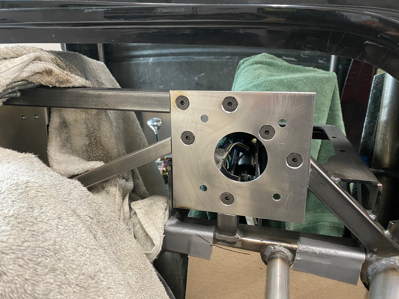
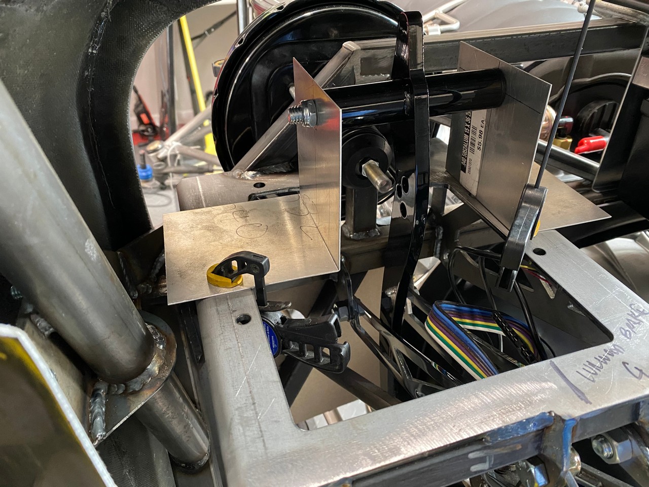
After finalizing the location, cut the hole in the frame as I mentioned last time. I bought a 12" x 12" x 0.1340" piece of steel sheet from McMaster. Nothing like that in any of the box stores. I had determined that .125 (1/8”) would be fine. But for whatever reason the exact material in 0.1340 was much cheaper. And since this is a budget build (!!!) went for it. Cut a roughly 6” square piece for the firewall mount and cut the frame so it’s sits flush. If I welded, I would have welded in. But I don’t. Taking the frame to a welder or having one come to my garage I decided wasn’t necessary. I bolted in place with six grade 8 5/16” flat head screws, hardened washers, and distorted thread locknuts. The 1/8” aluminum firewall will be bonded and riveted over the whole thing and add another layer of strength. I’m confident it’s not going anywhere. Here is the plate installed and then the power brake assembly mounted.
Then onto the inside. I made two right angle brackets out of the same 0.1340" steel sheet that bolt to the shelf where the Wilwood pedal box would normally go. These also could have been welded. But are bolted in place with seven grade 8 5/16” rounded head screws, hardened washers, and distorted thread locknuts. Rock solid. I determined the height and location previously with quick mock-up pieces out of .040” aluminum. Then committed to the sheet steel and installed. Both the firewall plate and the angle brackets are now permanently mounted. I have no intention of removing them. They'll stay in place when I send the chassis out for powder coat.

The brake pedal itself and orientation is still a work in progress. The pieces I have can be installed several different ways. I’ve started work on the bracket to hold the LS drive-by-wire module (accelerator pedal) and will work those two things together to finalize the locations. Also seen in this picture is where I propped the steering shaft into it's intended location. Also that I moved the Ididit steering column mounting arm to the outside of the LH mount. Both necessary to finalize the proper location of the brake arm and in turn the booster/master cylinder. Everything gets pretty close in there.

With the booster mounted, brake arm swinging, clevis in place and adjusted, and getting the Wilwood specified 1.1” of pushrod travel, time to mount the master cylinder. I bought the master cylinder, booster, and pedal arm as a unit from the same company. Talked about that in a number of posts. Thought I'd use at least part of the included frame mount, but didn't. You’d think the pushrod between the booster and the Wilwood MC would be adjusted, right? Nope. I didn’t have a way to exactly measure, but with the adjuster on the booster pushrod all the way in, it was still too long for the Wilwood MC with the power brake slug installed in the piston. Not a lot, but not acceptable. There is supposed to be .020” of slack when together. After some Googling and YouTube viewing, repeatedly saw a tool that is used to measure and set the pushrod clearance. Not expensive at $25 or so. But then waiting begins again. Ran across a video where a guy made his own out of a piece of wood and a metal dowel. Inspired me to hit the shop and an hour later had my own out of 1/8” aluminum, a cut-off bolt, some tie wraps, and some instant glue. A little cheesy. But hey. Price was right and instant gratification. It’s not super critical except that the two ends need to be exactly parallel and the measuring rod the exact same length. Then, insert one end into the cup in the MC pushrod, make sure it’s seated, then measure the other side with a feeler gauge on the booster pushrod. Worked like a charm. I ground about 1/16” off the end of the slug in the MC piston, rounded it by spinning and filing in my drill press, then measured and set the booster pushrod. Harder to explain that actually doing. The MC is bolted in place and hopefully will stay there.

Next up is to finalize the DBW module as mentioned. I’ve got the last pieces for my dash so finalizing the layout. I'll show that soon. Then start mounting stuff behind the dash. As Mike Peaty says "Back to work!" If you haven't seen his aviation build videos, you're missing out. Check them on YouTube. Highly entertaining. Another person with mad skills. And clearly an unlimited budget.
Last edited by edwardb; 04-18-2021 at 05:44 AM.
Build 1: Mk3 Roadster #5125. Sold 11/08/2014.
Build 2: Mk4 Roadster #7750. Sold 04/10/2017.
Build Thread
Build 3: Mk4 Roadster 20th Anniversary #8674. Sold 09/07/2020.
Build Thread and
Video.
Build 4: Gen 3 Type 65 Coupe #59. Gen 3 Coyote. Legal 03/04/2020.
Build Thread and
Video
Build 5: 35 Hot Rod Truck #138. LS3 and 4L65E auto. Rcvd 01/05/2021. Legal 04/20/2023.
Build Thread. Sold 11/9/2023.
-
Post Thanks / Like - 0 Thanks, 2 Likes
-
04-18-2021, 03:49 PM
#143
Senior Member

Some really nice work and even better documentation of it!!
Thank you 😊
-
Post Thanks / Like - 0 Thanks, 1 Likes
-
04-18-2021, 09:00 PM
#144
Senior Member

Originally Posted by
edwardb
...As Mike Peaty says "Back to work!" If you haven't seen his aviation build videos, you're missing out. Check them on YouTube. Highly entertaining. Another person with mad skills. And clearly an unlimited budget.
Couldn't agree with you more! Can't wait to see the wings go together on Scrappy. In addition to his budget, I also I wish I had his kind of energy.
-
Post Thanks / Like - 1 Thanks, 0 Likes
-
04-20-2021, 08:14 PM
#145
Senior Member
Pedals and Dash
Finished mounting the DBW. Made a plate that attaches to the side of the shelf intended for the Wilwood pedal box. Made out of the same steel as the pieces shown previously for the power brake mounting. I had to bend it slightly to give proper clearance off the fiberglass transmission tunnel. But other than that, was in good alignment with where it needed to be. With that, adjusted and oriented the brake pedal. This picture angle doesn’t quite give the right perspective. The brake pedal is about 1-1/2” inches above the accelerator pedal. Looks further from this angle. See how that works once they’re bled and powered. Can be adjusted if needed. The finish between the two pedals isn’t exactly compatible either. See if that still bothers me down the line. But it’s all done and functional for now.

The pedal exercise demonstrates for me anyway why the truck has a reputation for not having a lot of foot space and not ideal for tall people. With the right seats, I think will be OK for us. But for taller folks maybe not so much. One of the reasons I went with automatic, other than it fit the theme of the build, was to eliminate the clutch pedal and make more room for my feet. The trade-off there is with the width of the automatic, the transmission cover needs to stay full width. In fact, needs to be stretched open a bit for my 4L65E. That dictated the position of the DBW as pictured above. This compared to a manual transmission where the instructions say you can cut the cover and take out an inch or two. That would allow the accelerator to move over some. But then with two additional pedals. Positives and negatives with everything.
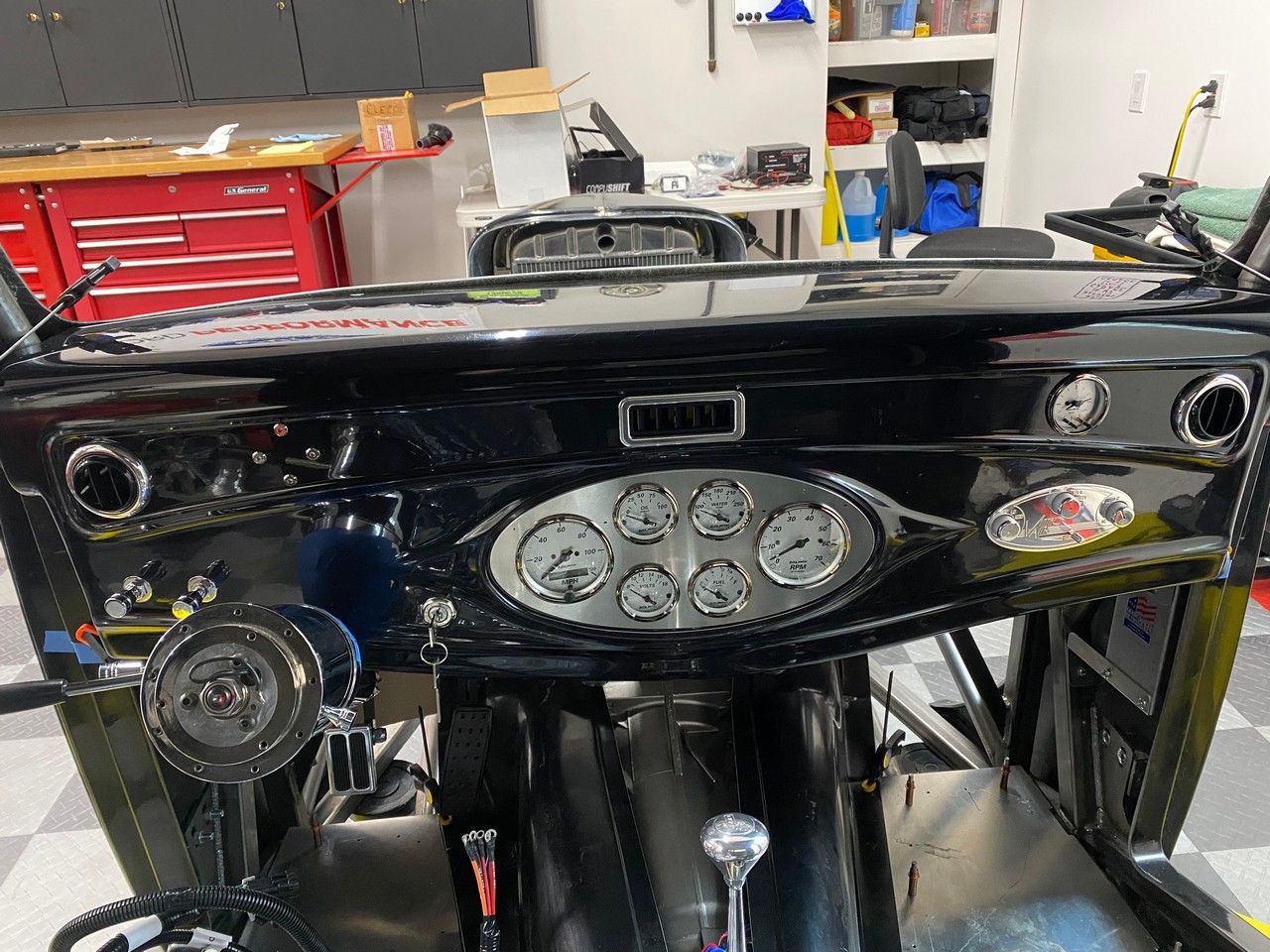
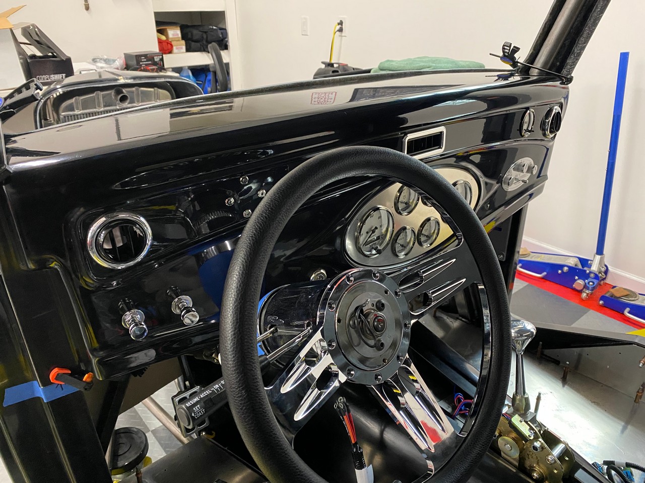
Today I finished the dash layout. Happy with how it turned out. I have A/C outlets on each end and in the center. On the LH side of the steering wheel I have the headlight switch from the kit and the wiper/washer switch from the Specialty Power Windows WWK2 wiper system. I bought Ididit knobs for each that match the knobs on the Ididit steering column. I’ve got LED indicators above the steering column for turn signals, high beam and MIL. Some put those around the gauges in the center. I need them right in front of me where they hit me in the face. The ignition switch is to the right of the steering column. Like many, I was disappointed to hear Factory Five lost their vendor for the former switch. An occasional quality issue. But looked good and the FFR logo'd keys were nice. The switch that came with my kit was very industrial (I'm being kind) and not going on my dash. I went with a Pollak 31-180P switch. Suggested on the forum, < $25 on Amazon, and looks decent. The gauge cluster is the kit supplied plate and Autometer gauges. Still undecided how I’ll finish the plate. I chose a Vintage Air Gen II dash control panel that has the same shape as the center gauge cluster. I think it looks cool. Seems like very nice quality. Knobs are lit along with the rest of the dash lighting. Played around with several locations and ended up on the passenger side. Given the size of the cab and the dash, still a relatively easy reach from the driver’s seat. It’s directly in front of the evaporator unit so wiring is simplified a bit. Plus closest to the person who would adjust it the most... I like a clock in my builds so ordered a matching clock from Autometer. Ended up in the location shown. It’s also actually backlit (are you listening Speedhut?). Finally put a USB aux connector on the lower edge of the dash on the driver side, and a regular aux connector on the passenger side. The regular one will be unswitched to the battery. So it’s always available, plus makes it useful for battery checking and tender connection. Did the same thing on my Coupe and it works great. Especially useful here since the battery is on the underside of the bed.

So now the fun really starts. Behind the dash I’m planning to add: RF panel and harness (dieted), LS power distribution box, LS PCM and harness, transmission controller, PS controller, cruise control module, and the Ididit high/low beam relay pack. Leaving room for A/C and defrost ducts, and A/C and heater hoses. Fortunately, there’s quite a bit of room. But still will be interesting.
Last edited by edwardb; 04-20-2021 at 08:35 PM.
Build 1: Mk3 Roadster #5125. Sold 11/08/2014.
Build 2: Mk4 Roadster #7750. Sold 04/10/2017.
Build Thread
Build 3: Mk4 Roadster 20th Anniversary #8674. Sold 09/07/2020.
Build Thread and
Video.
Build 4: Gen 3 Type 65 Coupe #59. Gen 3 Coyote. Legal 03/04/2020.
Build Thread and
Video
Build 5: 35 Hot Rod Truck #138. LS3 and 4L65E auto. Rcvd 01/05/2021. Legal 04/20/2023.
Build Thread. Sold 11/9/2023.
-
Post Thanks / Like - 1 Thanks, 2 Likes
-
04-21-2021, 01:29 AM
#146
Dreamer

Lokar has DBW pedals that may match your brake pedal....
-
04-21-2021, 01:55 AM
#147
 Administrator

Paul I’d e happy to engine turn that gauge cluster if you decide to go that direction. Maybe I’ll order one from the factory, finish it and send it out to if you decide to give it a try. That way if you don’t like it no harm no foul.

FFR 5369 Pin Drive, IRS, Trigos, Torsen, Wilwoods, FMS BOSS 302 "B" cam , Mass-flo. CA SB100 (SPCN) Registered
Delivered 4/23/06. "Finished" 4/2012 (still not done!)
-
04-21-2021, 07:08 AM
#148
Senior Member
Originally Posted by
j33ptj
Lokar has DBW pedals that may match your brake pedal....
What a great suggestion! I knew that Lokar had Coyote DBW modules and a selection of pedals that go with them. Have considered those for my Coyote builds but never went that way. Stands to reason they have similar products for the LS. But wasn't aware they had pedals that change out on existing GM DBW modules so never looked. Turns out they have one that exactly fits the part number GM DBW I have and matches my brake pedal. Which is just a generic Speedway part. Not Lokar. Who knew? I'm going for it. Thanks again.
Originally Posted by
David Hodgkins
Paul I’d e happy to engine turn that gauge cluster if you decide to go that direction. Maybe I’ll order one from the factory, finish it and send it out to if you decide to give it a try. That way if you don’t like it no harm no foul.
PM sent.
Build 1: Mk3 Roadster #5125. Sold 11/08/2014.
Build 2: Mk4 Roadster #7750. Sold 04/10/2017.
Build Thread
Build 3: Mk4 Roadster 20th Anniversary #8674. Sold 09/07/2020.
Build Thread and
Video.
Build 4: Gen 3 Type 65 Coupe #59. Gen 3 Coyote. Legal 03/04/2020.
Build Thread and
Video
Build 5: 35 Hot Rod Truck #138. LS3 and 4L65E auto. Rcvd 01/05/2021. Legal 04/20/2023.
Build Thread. Sold 11/9/2023.
-
Post Thanks / Like - 1 Thanks, 0 Likes
-
04-21-2021, 11:49 AM
#149
Senior Member

There is SO much more room in the footbox with only two pedals!  Great work so far.
-
Post Thanks / Like - 0 Thanks, 1 Likes
-
04-22-2021, 12:45 AM
#150
Top Notch Builder

Paul,
Fantastic job, amazing how much progress you’ve made. What a list of stuff to get behind the dash, WOW! Knowing you it’s going to be amazing. Keep up the good work. I love reading your updates.
- Danny
-
Post Thanks / Like - 1 Thanks, 0 Likes
-
04-22-2021, 04:31 PM
#151
Senior Member

MK4 #8900 - complete kit - Coyote, TKO600, IRS - Delivered 6/28/16 First Start 10/6/16 Go cart - 10/16/16 Build completed - 4/26/17 - 302 days to build my 302 CI Coyote Cobra - Registered and street legal 5/17/17
Build Thread
http://thefactoryfiveforum.com/showt...e-build-thread
PHIL 4:13 INSTAGRAM - @scottsrides
-
Post Thanks / Like - 1 Thanks, 0 Likes
-
04-25-2021, 07:51 PM
#152
Senior Member
Electrical Rough-In
Nearly done with figuring out the layout for all the major electrical components behind the dash. The good news is the truck actually has quite a bit of room. More than the 33 Hot Rod and certainly more than my Gen 3 Coupe. But of course I’m doing my best to fill it up and make it as complicated as possible. 
My design goals included:
- The larger and much more DD-ish Vintage Air 960-68000-VUZ-A Gen II ComPac evaporator shown previously. Has separate ducting for floor, dash, and defrost, servo controls for each, blend modes, etc. Note I’m not using the Factory Five optional system. Buying all the parts separately. Mainly Vintage Air stuff. Best I can tell, Factory Five is supplying the same Siroco Boreal evaporator I have from their kit in my Coupe for the Hot Rod and truck. It’s very compact and just fits in the Coupe. Probably the same for the Hot Rod. But it’s a very basic unit with two outlets that are either on or off. It works OK in our Coupe but taking advantage of the available space for a more sophisticated setup.
- LS3 PCM and power distribution box behind the dash rather than in the engine compartment. A matter of space mainly. But also for underhood appearance. Also, while I don’t mind tearing into wire harnesses in general, I really didn’t want to break into the LS3 harness. This allows much of the harness to be behind the dash.
- RF panel in the recommended location in the LH upper part of the driver’s footbox.
- Addition of modules for the automatic transmission, power steering, headlights, and cruise control. Not having the Wilwood pedal box gave me a little more room and freedom for placement.
- Under dash access to as much as possible including fuses, relays, etc. But fully realize that it might be necessary to remove the dash for major components. Fortunately, while some effort would be required and hope it won’t be necessary, appears the dash is removable in the completed truck.
So with that, started placing components and fabricated some parts in the process. Used my new Woodward Fab brake for several. Loving it. First up was the RF panel. The kit comes with a frame to hold it. But since I don’t have the Wilwood pedal box, I decided to make my own that fits a little better and attaches at both ends. I cut a notch so it didn’t cover up my chassis number.

Next up was the LS3 power distribution box. After looking at everything, decided the best location was on the end of the Vintage Air evaporator. So fabricated some brackets attached to the previous plate I made to hold the evaporator. For space purposes, I won’t use the cover. Just leave it open like the RF panel. It’s not super handy, but all the components on the panel are reachable from underneath. Haven't had to touch any of the parts in the PDB's on the two Coyote builds I've done. Hoping this is the same. With that in place, made brackets to hold the PCM and the transmission controller. The cables for the PCM will go across the top of the evaporator and exit at the top corner of the firewall. Then just a single run over to the back center of the engine and onto all the engine connections from there. Pretty clean. The cables for the transmission controller are a straight shot down to the transmission. The power steering controller is on the LH side of the pedal box shelf, and the headlight relay pack right behind it.
The pictures below show everything. Plus (after a lot of thought…) made a panel that will mount on the front of the evaporator using existing mounting locations. Right now it’s a blank canvas. But will have a couple bus bars, circuit breakers, and relays. Should work well. Post 119 has a spreadsheet with my wiring plan. My initial idea was to have these parts over on the footbox shelf. But getting pretty congested. Plus this area is wide open. Several inches to the back side of the dash through that whole area. Also visible in these pics is the shiny new Lokar accelerator pedal. Not cheap but a very nice quality part that looks much better than the stock pad and basically matches the brake pad. Thanks j33ptj.


Couple comments about this final electrical layout. First, while other builders may get some ideas (or not…) what I’m doing is very specific to the combination of engine, trans and options I chose. So not sure how much would be usable for other selections. The other day someone on Facebook said these builds were like assembling IKEA furniture. Follow the manual you’ll have a car. Well, that’s for sure not true with this build. But not true with any others either IMO. Just a matter of degrees. That's a whole other discussion. Second, while it might be possible to stuff the RF harness in there as-is, that’s not what I’m going to do. When it comes time for actual wiring, I’m planning to strip it completely down and diet out a whole bunch. Wiring will basically be point-to-point and most connectors removed. Just leave what’s necessary to unplug and remove the dash as I mentioned before. Again, this isn’t for everyone but how I’m going to do it. The harness in my Coupe was probably about 50% torn apart. This one will be a lot more. Hard to make the behind-the-dash area pretty. But it will be neat and organized as much as I can. And by the way, I've been watching very closely and so far have plenty of room for the ducting that will be added. It was a major pain getting all that to fit in the Coupe. This looks to be much easier. Even with everything I added. Also I'm clear of the planned wiper and wiper box locations shown previously. Third, while not part of the scope of this update, the heater and A/C hoses will exit to the right and just below the evaporator in the corner of the passenger footbox. Planning to also put the heater valve in that location. Have seen pictures of several other builds doing that and looks like it will work for me. I'm counting on it.
That’s it for now. A couple minor details and the body is coming off. Finally. Then finish aluminum layout and drilling. Then tear everything down and get the chassis and tins powder coated. While that’s happening, I’m going to start working on cleaning up all the fiberglass parts.
Last edited by edwardb; 04-26-2021 at 05:13 AM.
Build 1: Mk3 Roadster #5125. Sold 11/08/2014.
Build 2: Mk4 Roadster #7750. Sold 04/10/2017.
Build Thread
Build 3: Mk4 Roadster 20th Anniversary #8674. Sold 09/07/2020.
Build Thread and
Video.
Build 4: Gen 3 Type 65 Coupe #59. Gen 3 Coyote. Legal 03/04/2020.
Build Thread and
Video
Build 5: 35 Hot Rod Truck #138. LS3 and 4L65E auto. Rcvd 01/05/2021. Legal 04/20/2023.
Build Thread. Sold 11/9/2023.
-
Post Thanks / Like - 1 Thanks, 1 Likes
-
04-25-2021, 08:33 PM
#153
Senior Member
Thats a lot of electrical pixies youre wrangling there!!
Kudos!! 👍🏼👍🏼
Last edited by Pat Landymore; 04-26-2021 at 06:42 AM.
-
04-26-2021, 07:03 AM
#154
Dreamer
The accelerator pedal looks so much better!!!
-
Post Thanks / Like - 0 Thanks, 1 Likes
-
04-26-2021, 08:45 PM
#155
Senior Member
Some days you put things together. Other days you take things apart. Body off and bunch of parts removed. With everything out of the way, decided I could move my DBW/accelerator toward the front about 1-1/8". Still not for long leg drivers. But every little bit helps. The wood pile in the driver's side is me experimenting with different seat heights. Lots of headroom in the truck and raising the seat helps with the legroom. The standard Roadster seat on that pile is about right for me. But probably won't use those particular seats. The engine/trans will be coming out next.

Last edited by edwardb; 04-26-2021 at 08:50 PM.
Build 1: Mk3 Roadster #5125. Sold 11/08/2014.
Build 2: Mk4 Roadster #7750. Sold 04/10/2017.
Build Thread
Build 3: Mk4 Roadster 20th Anniversary #8674. Sold 09/07/2020.
Build Thread and
Video.
Build 4: Gen 3 Type 65 Coupe #59. Gen 3 Coyote. Legal 03/04/2020.
Build Thread and
Video
Build 5: 35 Hot Rod Truck #138. LS3 and 4L65E auto. Rcvd 01/05/2021. Legal 04/20/2023.
Build Thread. Sold 11/9/2023.
-
Post Thanks / Like - 0 Thanks, 1 Likes
-
05-02-2021, 04:49 PM
#156
Senior Member
More Electrical Plus
A little bit of a slow week for progress. I showed in a previous post that we took the body off. First time off since delivery. Can’t work around it any longer. But it was very helpful having it there while placing as much as I could. I was planning to store it in my SE trailer. But managed to fit it in the garage bay along with the riding mower, generator, etc. It’s not all that big once off the chassis. All the rest of the fiberglass parts are spread around in my basement. With the body off, finalized the various electronic module mounts described previously. Not much more to do there until it all goes back in after powder coat and wiring begins.
Speaking of wiring, I have a plan now for my power wiring. I’ve decided I’m not going to do a master disconnect like on previous builds. The kit location for the battery is in a tray under the bed right behind the cab. Not super handy, but that’s where it’s going to be. So I’m planning the following:
- #2 cable from the battery ground to the chassis at the battery location.
- #2 cable from the battery positive to a feedthrough on the firewall. Attached to the same stud on the firewall side will be a short piece to the starter and another length to the alternator through a megafuse.
- On the cockpit side of the feedthrough, will route to a bus bar shown below. The two main power wires from the RF harness will be on that bus bar along with a couple other connections that need always on battery power. I may go to the LS power box from the bus bar. Or maybe directly from the feedthrough. Haven’t decided yet.
The battery bus bar is on the panel I made that mounts on the front of the A/C evaporator. Shown earlier. Kind of a strange location. But it’s open real estate behind the dash and will get a lot of the wiring away from the driver side where things are quite congested. I think it’s going to work out well. With that, have the panel configured and assembled. The battery bus bar (a Blue Sea Systems piece) is on the right. Another one on the left for several ignition powered functions. I have circuit breakers placed for the three circuits where they’re needed. On the LH side are two relays. One for the Watson's Streetworks headlight warning chime next to it (something I’ve put on all my builds) and the other for the brake light circuit going to the cruise control. According to the instructions from Dakota Digital, if LED brake lights are used a relay must be added to the circuit. The bus bars and circuit breakers all have covers that will be added when done. I posted a spreadsheet earlier with my detailed electrical plan if you want more details of what all this is for.


Something else I completed this week was mounting the AC condenser on the radiator and front grille. Here I’m paying the price for not buying the Factory Five heat/AC kit. I bought a Vintage Air 03032-OFV 20-3/4” x 14” condenser kit. Came with mounting brackets but no surprise they don’t fit the radiator/grille setup. I have no idea if the ones that Factory Five made for their setup would fit this particular condenser. I fabricated my own out of 16 gauge sheet steel. Probably overkill but they’re solid. There isn’t a lot of room to add thickness to the radiator/condenser stack in the grille or it runs into the chassis. So I kept everything as tight as possible and it’s going to work. Happy with how it turned out. I have hard lines that came with the kit from Vintage Air. May work but won’t know until later in the build. Vintage Air will make custom ones. Or they sell “U-Bend It” pieces. We’ll see.

Not remotely enough room here for the transmission cooler that came with my auto trans. I’ll be mounting a Derale 13950 powered cooler under the bed in the back. Already have it. One side benefit is that’s two fewer hoses I have to run to the front of the truck. Trans cooling lines will be relatively short to the back.
I’m working now on finalized the aluminum panels in the cockpit. Not much left to do there. Two of the bigger pieces in the rear corners of the cab can’t be drilled or mounted until the cab is back on. Once the cockpit aluminum is done, going to pull the LS and trans back out and finalize the firewall. Then it’s time to take everything else apart and find a powder coater for the chassis.
Last edited by edwardb; 05-05-2021 at 06:27 AM.
Build 1: Mk3 Roadster #5125. Sold 11/08/2014.
Build 2: Mk4 Roadster #7750. Sold 04/10/2017.
Build Thread
Build 3: Mk4 Roadster 20th Anniversary #8674. Sold 09/07/2020.
Build Thread and
Video.
Build 4: Gen 3 Type 65 Coupe #59. Gen 3 Coyote. Legal 03/04/2020.
Build Thread and
Video
Build 5: 35 Hot Rod Truck #138. LS3 and 4L65E auto. Rcvd 01/05/2021. Legal 04/20/2023.
Build Thread. Sold 11/9/2023.
-
Post Thanks / Like - 0 Thanks, 2 Likes
-
05-02-2021, 06:22 PM
#157
Senior Member
Youre doing awesome work there!
Do you know if the optional grille shell you are using is any deeper than the standard 35 one? I found it somewhat challenging just mounting my trans cooler and running lines in front of the rad. Cant imagine mounting/plumbing AC hardware
🤦
-
05-02-2021, 07:41 PM
#158
Senior Member
Originally Posted by
Pat Landymore
You’re doing awesome work there!
Do you know if the optional grille shell you are using is any deeper than the standard ‘35 one? I found it somewhat challenging just mounting my trans cooler and running lines in front of the rad. Can’t imagine mounting/plumbing AC hardware… ��
Thanks. My grille is the #33006 front grille. I think the standard one. The Factory Five order form shows a 34914 - Deluxe Hot Rod Truck Grill. I don't really know the difference to be honest. I think it has a more rounded bottom like in some of the gallery pictures. But I don't know for sure if that's the only difference and certainly not if there's a difference in thickness or available space. What I do know is that it became obvious very quickly that there's no way I could get both the AC condenser and auto trans cooler in the grille I had along with the radiator. And my transmission builder was very adamant about providing adequate cooling. So I knew I'd be doing a separate power cooling setup almost from the beginning.
Build 1: Mk3 Roadster #5125. Sold 11/08/2014.
Build 2: Mk4 Roadster #7750. Sold 04/10/2017.
Build Thread
Build 3: Mk4 Roadster 20th Anniversary #8674. Sold 09/07/2020.
Build Thread and
Video.
Build 4: Gen 3 Type 65 Coupe #59. Gen 3 Coyote. Legal 03/04/2020.
Build Thread and
Video
Build 5: 35 Hot Rod Truck #138. LS3 and 4L65E auto. Rcvd 01/05/2021. Legal 04/20/2023.
Build Thread. Sold 11/9/2023.
-
Post Thanks / Like - 1 Thanks, 1 Likes
-
05-04-2021, 02:25 PM
#159
Senior Member
Yes, I like me some clecos. Not going to talk me out of any of them.  Rear cockpit wall is fitted and drilled. There's a piece that goes across the top. Visible in the pic. The manual is very specific about how it's located. But since it has a flange for the rear of the cab, I'm going to leave it off until the cab is back on to make sure it's placed exactly right. I'm waiting to place the driveshaft cover until the fiberglass transmission cover is placed, and that's dependent on the firewall. Which is next.

Build 1: Mk3 Roadster #5125. Sold 11/08/2014.
Build 2: Mk4 Roadster #7750. Sold 04/10/2017.
Build Thread
Build 3: Mk4 Roadster 20th Anniversary #8674. Sold 09/07/2020.
Build Thread and
Video.
Build 4: Gen 3 Type 65 Coupe #59. Gen 3 Coyote. Legal 03/04/2020.
Build Thread and
Video
Build 5: 35 Hot Rod Truck #138. LS3 and 4L65E auto. Rcvd 01/05/2021. Legal 04/20/2023.
Build Thread. Sold 11/9/2023.
-
05-04-2021, 02:57 PM
#160
Senior Member

I guess I'll be the first to say it: Wow! That's a lot of clecos! I think you surpassed what I installed on my rear cockpit wall! Impressive. Maybe I can blame my Cleco proclivities on you.
Nice work, Paul! You continue to set the build standard for me. I'm enjoying following along.
Chris
Coupe complete kit delivered: 4/22/24.
Build Thread. Coyote. T-56. IRS w/3.55. Wilwoods. PS. HVAC. Side windows.
MK4 Complete kit.
Build Thread Index. Delivered: 10/15/2020. Legal: 7/25/23. Coyote Gen3. TKO600 (0.64 OD). IRS w/3.55. PS. Wilwoods. Sway bars. This build is dedicated to my son, Benjamin.
Build Thread.
-
Post Thanks / Like - 1 Thanks, 1 Likes


 Thanks:
  Likes:


 Reply With Quote


