BluePrint Engines

Visit our community sponsor

Thanks Thanks:  0
Likes Likes:  0
Results 1 to 9 of 9

Thread: How-To Super Port J-Pipes

  1. #1
    Member dv/dt's Avatar
    Join Date
    Feb 2011
    Location
    Ottawa, Canada
    Posts
    97
    Post Thanks / Like

    Lightbulb How-To Super Port J-Pipes

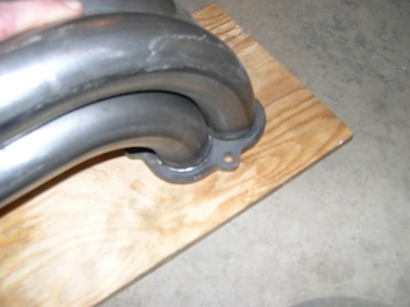
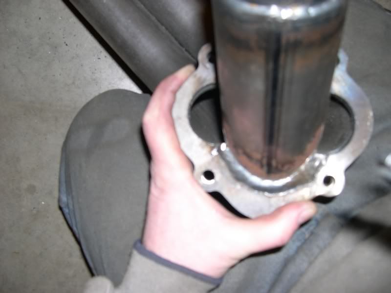
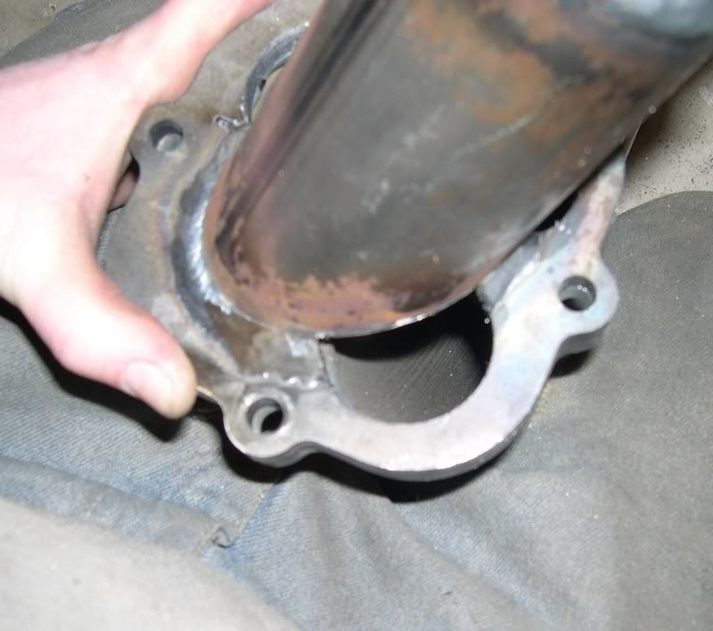
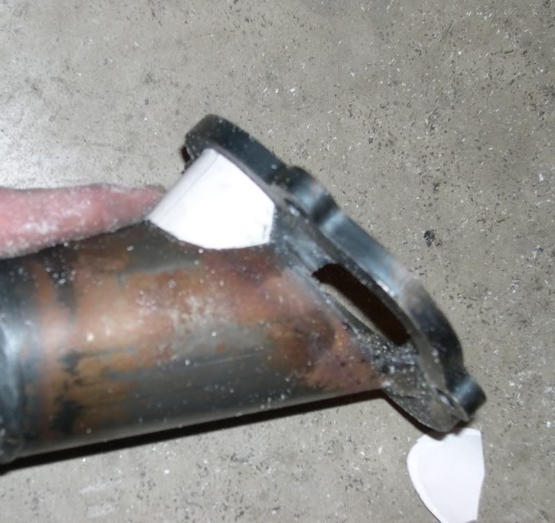
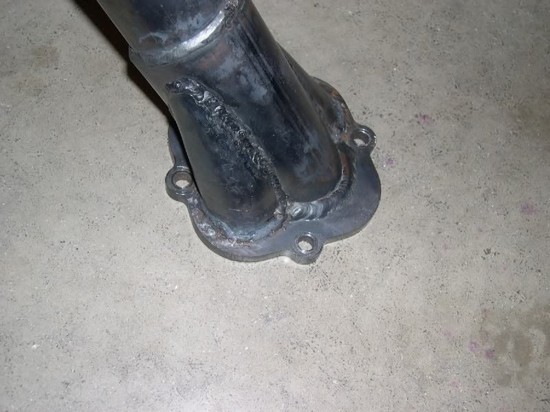
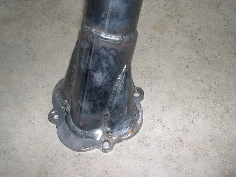
    Here are the instructions for super porting the J-Pipe. Do it at you own risk and use all appropriate safety precautions !!

    When used on conjunction with the Aerospike Mod they were good for 23 hp during our exhaust shoot out.

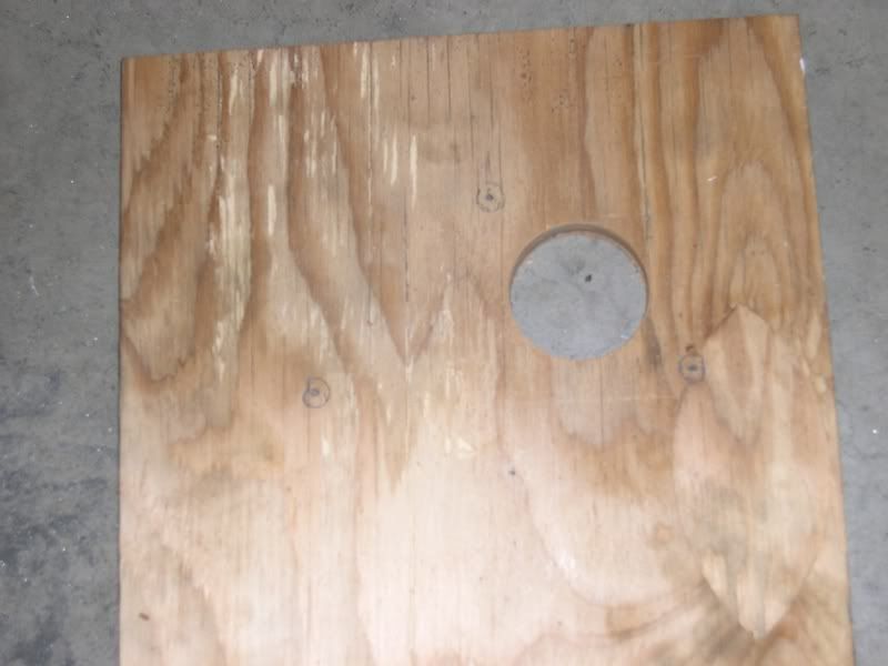
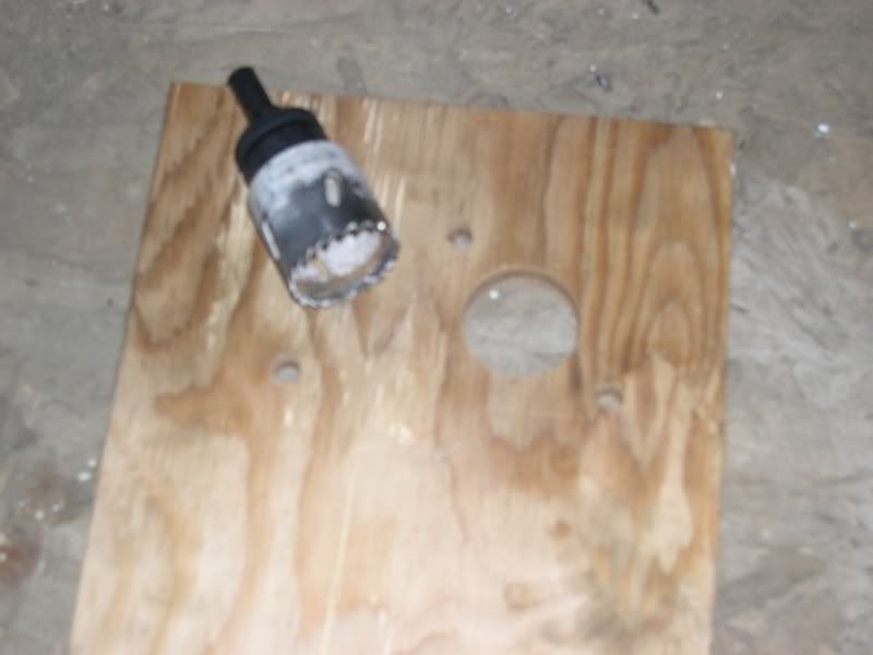
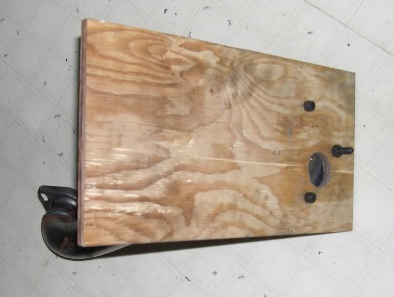
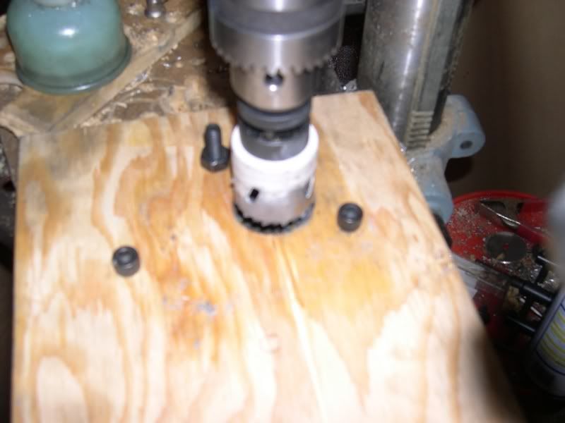
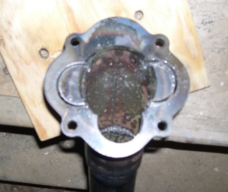
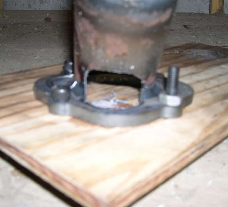
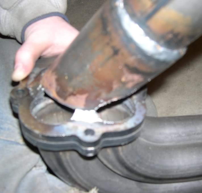
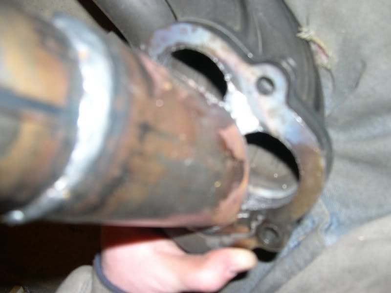
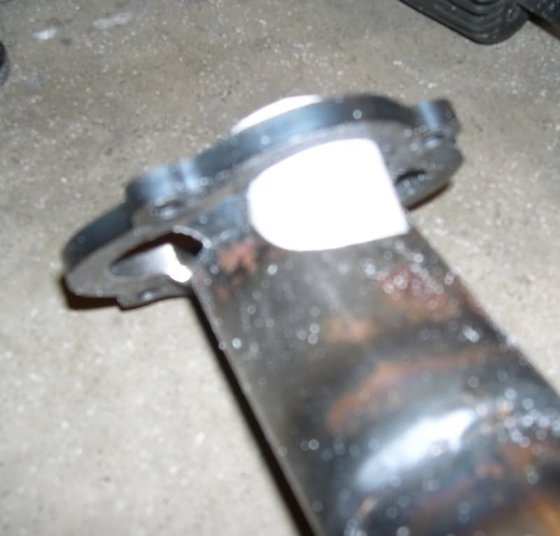
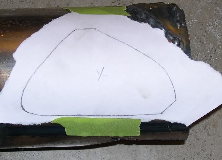
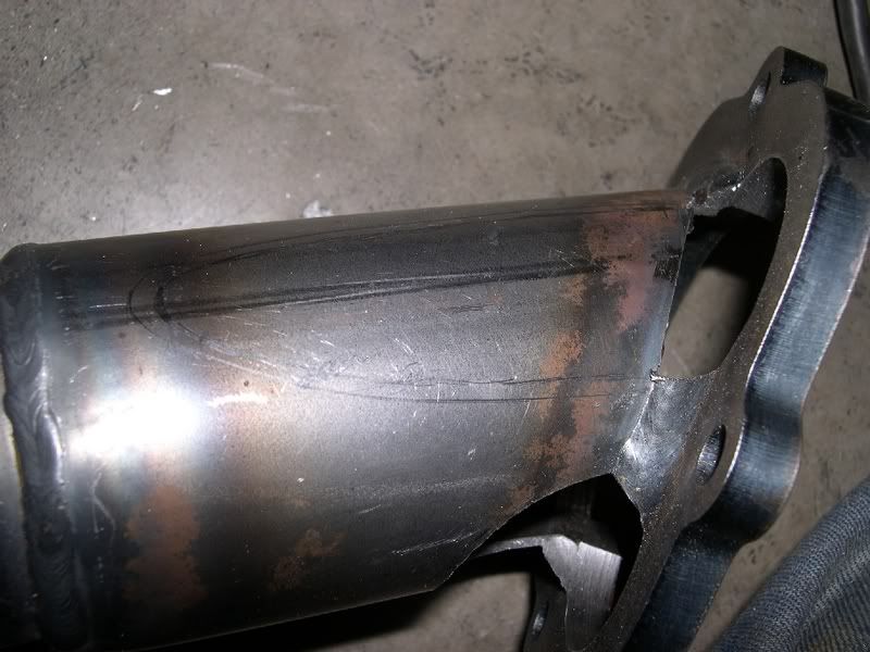
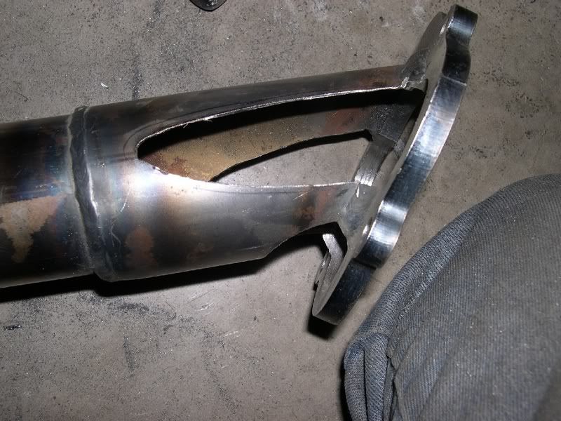
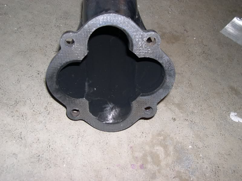
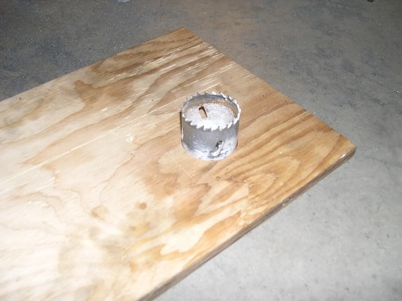
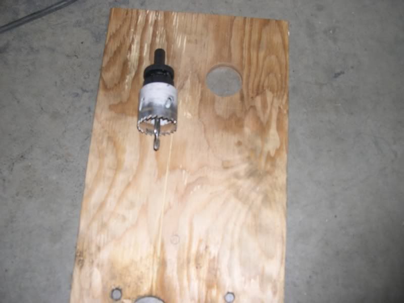
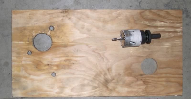
    I started by making a drill guide for cutting the port pattern in the J-pipe flange. This is a piece of ½” plywood about 8” x 20”. You want the length to help counter the drill press torque. The hole saw is a 1-3/4” bimetal and use the pilot bit for making this hole. You can see where we’re going as the guide for the 1st pipe is on the other end.


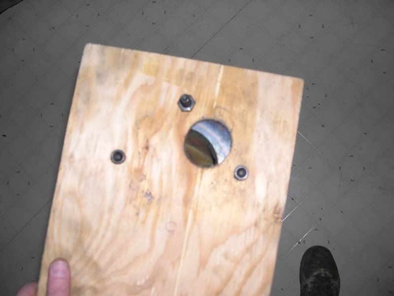
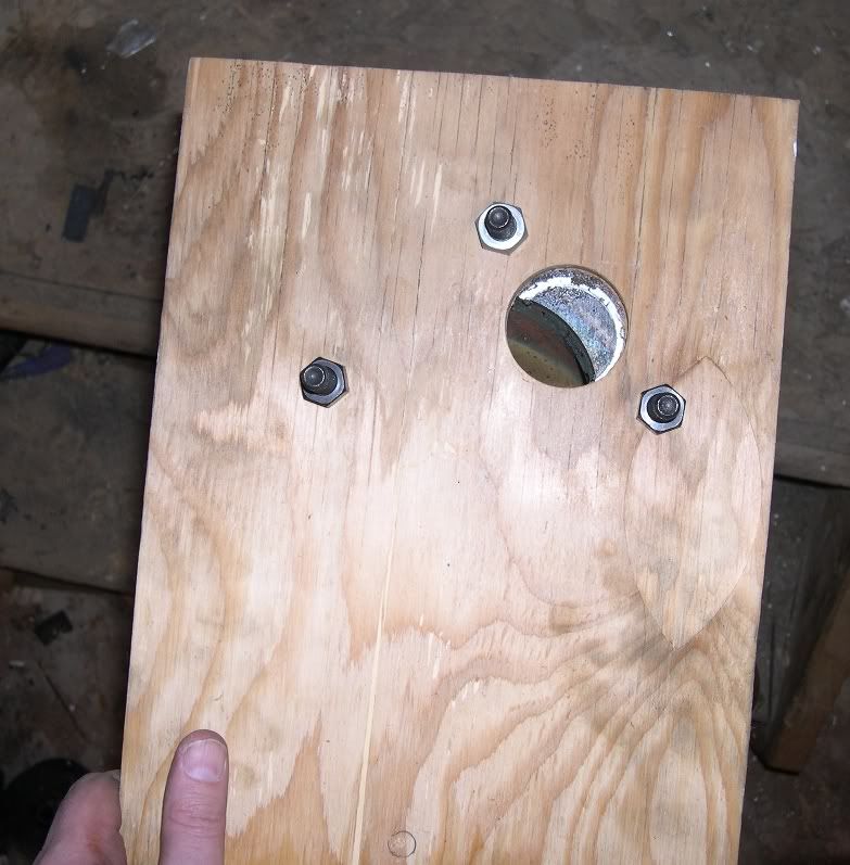
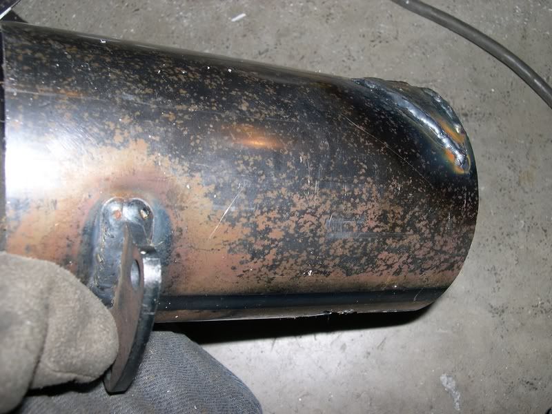
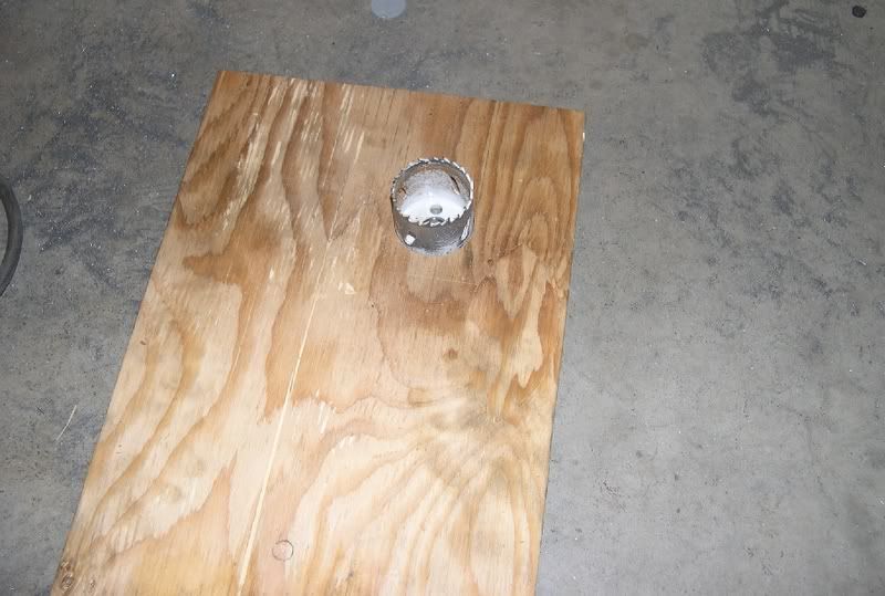
    I then took the drill apart and placed the cup into the hole.


    Last edited by dv/dt; 02-13-2011 at 10:59 AM.

  2. #2
    Member dv/dt's Avatar
    Join Date
    Feb 2011
    Location
    Ottawa, Canada
    Posts
    97
    Post Thanks / Like
    Place the sidepipe flange over the drill and center it as best you can. It’s a close but not tight fit so move it around to “feel” for the center. Then mark the three accessible bolt holes.


    Drill the three mounting holes and reassemble the hole saw without the pilot drill.


    Attach the guide plate to the J-pipe flange. You can see here how much of the ports are shrouded.


  3. #3
    Member dv/dt's Avatar
    Join Date
    Feb 2011
    Location
    Ottawa, Canada
    Posts
    97
    Post Thanks / Like


    Using a drill press and holding the guide plate securely you can carefully cut the flange. The hole saw will grab the wood if not lined up correctly and will most likely snag on the metal several times while drilling. This will get worse once you are through the flange and into the weld. Be careful!!


    Here you can see the saw has just started cutting the flange.


    Here you can see (sorry it’s fuzzy) where the flange has been cut as well as the weld right to it’s root. You can now clock the guide 90° and you're ready for the next port.


  4. #4
    Member dv/dt's Avatar
    Join Date
    Feb 2011
    Location
    Ottawa, Canada
    Posts
    97
    Post Thanks / Like
    Here all three ports have been cut. The left and right one just go as far as the root of the weld. For the lower port (on the closed angle side) the hole saw was continued all the way down to cut the pipe as well. The hole saw snagged often on the thin sheet metal so hold on. For the forth port I opened it up using a grinder since it had to be cut at an angle or you will cut into it’s weld.


    You can see here how the ports line up. That just has to flow better!


  5. #5
    Member dv/dt's Avatar
    Join Date
    Feb 2011
    Location
    Ottawa, Canada
    Posts
    97
    Post Thanks / Like


    I then used some 2” central vac tubing to mock up the diffusers. It cuts fairly easy and can be made to a smaller radius (~1-3/4”) by heating it a bit with a heat gun (or probably a good hair drier). You kind of on you own here as it is trial and error but you want to get this as close as you can because working with the metal versions is much harder.


    For the closed angle port snap a piece of tubing into the cutout and mark the outline with a pencil.


  6. #6
    Member dv/dt's Avatar
    Join Date
    Feb 2011
    Location
    Ottawa, Canada
    Posts
    97
    Post Thanks / Like
    Remove it and mark the flange end about 1/8” from the pencil line and do the same for both the weld lines. You can see the original lines and the new cut lines in this fuzzy picture.


    Should fit like this.


    Once you have all the patterns cut out of plastic you need to trace them onto paper. Wrap the paper on the outside of the pattern and mark the outline.


    Remove the paper and trace the pattern through the paper to the other side of the paper. Mark that side with an X so you know which side of the pattern is good. I also suggest that you mark the orientation of the pattern on the tube (not shown here).


  7. #7
    Member dv/dt's Avatar
    Join Date
    Feb 2011
    Location
    Ottawa, Canada
    Posts
    97
    Post Thanks / Like
    Tape the pattern to the metal. I used some 16 gage scrap but would strongly suggest you find some 16 gage 1-3/4” tubing to save a LOT of work. Make sure you line it up so the curve is the same as the plastic pattern (this one isn’t and resulted in a LOT more work!).


    I then used a sharp utility knife to cut through the pattern and mark the metal which you can just make out in this pic.


    Here are the three diffusers. The one on the left is the one with the wrong orientation and I had to pound it flat and rebend it. Save yourself the trouble and cut it right in the first place!


    Once you have the metal diffusers tweaked to fit just right place them on the J-pipe and mark their outline. Remove them and mark another line 1/8” inside of that line. This is your cut line.


  8. #8
    Member dv/dt's Avatar
    Join Date
    Feb 2011
    Location
    Ottawa, Canada
    Posts
    97
    Post Thanks / Like
    And cut.


    And weld away.


  9. #9
    Member dv/dt's Avatar
    Join Date
    Feb 2011
    Location
    Ottawa, Canada
    Posts
    97
    Post Thanks / Like
    And there you have it, one super ported J-pipe!


    Ask away if you have any questions.

    Cheers, Rod

Posting Permissions

  • You may not post new threads
  • You may not post replies
  • You may not post attachments
  • You may not edit your posts
  •  

FFMetal

Visit our community sponsor