BluePrint Engines

Visit our community sponsor

Thanks Thanks:  13
Likes Likes:  26
Page 17 of 28 FirstFirst ... 7151617181927 ... LastLast
Results 641 to 680 of 1106

Thread: Jazzman’s #8745 "Flip Top" Build

  1. #641
    Senior Member
    Join Date
    Apr 2011
    Location
    Shawnee KS< KC Burb
    Posts
    844
    Post Thanks / Like
    Quote Originally Posted by Jazzman View Post
    I began by gluing up two 3" thick blocks of structural foam 6" long.
    I set to work with a knife to cut away some of the excess, then worked the blocks down more with the sanding station.
    Jazzman
    Love watching your thread,
    The way you jump into each new aspect and conquer any obstacles gives me a nudge to move forward on my 33.
    The foam blocks look like the answer to one of my projects on the 33HR. Care to share the source and any details on what type of foam works best?
    Thanks
    Dale
    Hemi33

  2. #642
    Jazzman's Avatar
    Join Date
    Jan 2014
    Location
    Scottsdale, AZ
    Posts
    1,166
    Post Thanks / Like
    Quote Originally Posted by myjones View Post
    Jazzman
    Care to share the source and any details on what type of foam works best? Thanks
    Dale
    Hemi33
    Thanks for following along, Dale. I still find it overwhelming that so many people seem to find my build interesting. Doing a project like this requires an attitude of "I can do it . . . I just don't know exactly how yet!" Learning and problem solving are some of the best parts of this build. Now get back out to the shop and do than '33! If I can do it, anyone can!

    I will be happy to share whatever I can!! I am not enough of an expert to be able to speak with authority that this is "the best", but it was recommended by two people that have much more experience than I do. I know it works. The foam board is from Aircraft Spruce. Part #01-12800 H45 PVC FOAM Board 1"X32"X48", cost $76.75 when I purchased it. I think they may sell it in smaller sizes. For what it is worth, this is the same stuff I used beginning in post #258. The foam board itself is solid, but has very little structural strength in and of itself. The fiberglass layers over the the top of the foam are what really give it strength.

    Depending upon how much you need, I might be able to just cut off some of the excess that I have and send it to you. PM me more details of your project and how much you need if you are interested.
    Last edited by Jazzman; 02-22-2017 at 12:33 PM.
    Jazzman

    MKIV #8745 "Flip Top" Roadster, Custom Tilt front, Coyote Engine, Tremec TKO600, Custom Interior. Best of Show winner, Huntington Beach Cruise In 2018.

    1967 Ford Mustang Coupe build thread updated 1/22/2021

    Roadster Frame Dolly Plan

  3. #643
    Senior Member MPTech's Avatar
    Join Date
    Feb 2011
    Location
    St. Louis, MO
    Posts
    1,233
    Post Thanks / Like
    Blog Entries
    8
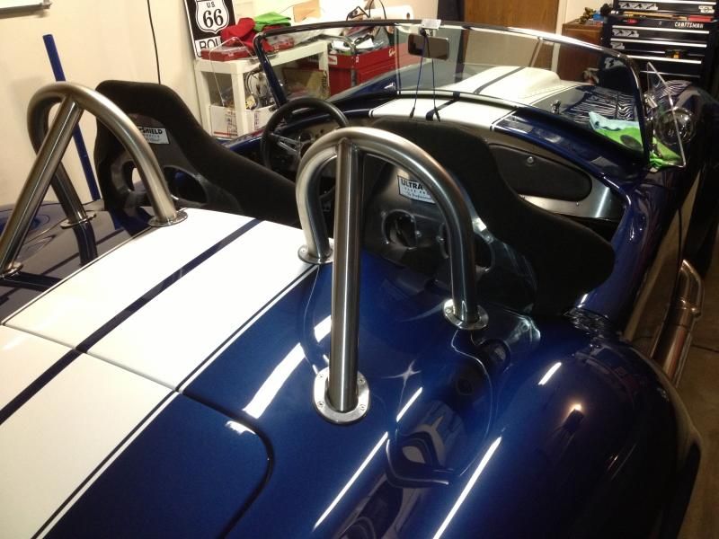
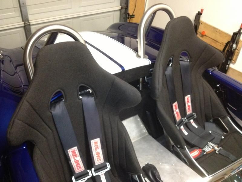
    Enjoying your thread as well, just caught up on your Rollbar installation.
    Yes they are a bit of a pain to have welded, drill the holes, and install (I learned to wear leather gloves when I installed the back legs, after getting the body back from paint. That slide-in leg can give one hell of a pinch blister!!)
    Yes they are a challenge, but I REALLY like them and they look even better after they are polished. Although my polisher cussed them out and had to upcharge me because they were difficult to hold and dangerous. After all the work, they are worth it and I've received several compliments on mine from other FFR owners that know the difference. Also like your additional lights installed in them. I went with the Russ Thompson trim rings and really like them too. Again, installation can be a challenge, especially of the rear legs. I had one trim-ring screw/nut that wanted to occupy the same space as the rear-leg bolt/nut.

    Here's mine before they were polished and the interior was completed


    That hood though. That is a piece of art and looks terrific. Nice job.
    F5R #7446: MK4, 302, T5 midshift, 3.55 Posi IRS, 17" Halibrands
    Delivered 4/4/11, First start 9/29/12, Licensed 4/24/13, off to PAINT 2/15/14!! Wahoo!

  4. #644
    Senior Member
    Join Date
    Aug 2014
    Posts
    127
    Post Thanks / Like
    Quote Originally Posted by Jazzman View Post
    Or perhaps I can come up with an alternative method of forming the foam box.
    I wonder if it would work to throw together a quick mold clamped to the back side of the panel and use the low expansion spray foam that is used for insulating around windows. I bet even the normal great stuff would work if you leave one side of the form open to allow it to expand without pushing on the panel. You can always carve up the resulting block to flatten faces as needed. The only trick would be if the spray foam sticks to the panel or form. I wonder if some strategically placed plastic wrap would do the trick.

  5. #645
    Senior Member
    Join Date
    Apr 2011
    Location
    Shawnee KS< KC Burb
    Posts
    844
    Post Thanks / Like
    Quote Originally Posted by jceckard View Post
    I wonder if it would work to throw together a quick mold clamped to the back side of the panel and use the low expansion spray foam that is used for insulating around windows. I bet even the normal great stuff would work if you leave one side of the form open to allow it to expand without pushing on the panel. You can always carve up the resulting block to flatten faces as needed. The only trick would be if the spray foam sticks to the panel or form. I wonder if some strategically placed plastic wrap would do the trick.
    I had the same thought, build a box form leaving the top open and spray it full. The box could be lined with a 1 gal ziplock bag for a bond break. Then cut off the overflow/top then remove the box, then cut away the bag and bond the piece to the body with HSRF. The spray it in a bag has been used on here before.
    DB

  6. #646
    Senior Member
    Join Date
    Apr 2011
    Location
    Shawnee KS< KC Burb
    Posts
    844
    Post Thanks / Like
    Quote Originally Posted by Jazzman View Post
    Thanks for following along, Dale. I still find it overwhelming that so many people seem to find my build interesting. Doing a project like this requires an attitude of "I can do it . . . I just don't know exactly how yet!" Learning and problem solving are some of the best parts of this build. Now get back out to the shop and do than '33! If I can do it, anyone can!

    I will be happy to share whatever I can!! I am not enough of an expert to be able to speak with authority that this is "the best", but it was recommended by two people that have much more experience than I do. I know it works. The foam board is from Aircraft Spruce. Part #01-12800 H45 PVC FOAM Board 1"X32"X48", cost $76.75 when I purchased it. I think they may sell it in smaller sizes. For what it is worth, this is the same stuff I used beginning in post #258. The foam board itself is solid, but has very little structural strength in and of itself. The fiberglass layers over the the top of the foam are what really give it strength.

    Depending upon how much you need, I might be able to just cut off some of the excess that I have and send it to you. PM me more details of your project and how much you need if you are interested.
    Thanks for the info, it sounds like a proven product based on your references above. And thanks for the offer to pass along the leftovers. BUT;
    I will probably need a whole sheet to thicken the 33 hood sides before I cut several long slots/vents into them. Once they are thick enough I will
    over cut the slots by 1/8" all around and glass the edges so it has a finished surface inside the openings. Then glass over the engine side to finish
    the look. I need to work up a shopping list for the first time fiberglass project and jump in feet first. That's what I did with all the fabrication for the
    custom suspension and hemi install but the bodywork has me intimidated for some reason. Might be the hella mess it makes but I'll get past it.
    Dale

  7. #647
    Jazzman's Avatar
    Join Date
    Jan 2014
    Location
    Scottsdale, AZ
    Posts
    1,166
    Post Thanks / Like
    Quote Originally Posted by myjones View Post
    Thanks for the info, it sounds like a proven product based on your references above. And thanks for the offer to pass along the leftovers. BUT;
    I will probably need a whole sheet to thicken the 33 hood sides before I cut several long slots/vents into them. Once they are thick enough I will
    over cut the slots by 1/8" all around and glass the edges so it has a finished surface inside the openings. Then glass over the engine side to finish
    the look. I need to work up a shopping list for the first time fiberglass project and jump in feet first. That's what I did with all the fabrication for the
    custom suspension and hemi install but the bodywork has me intimidated for some reason. Might be the hella mess it makes but I'll get past it.
    Dale
    Sounds like a plan! Let me know if there is anything I can do to help. It does make a heck of mess, but in the end, it's worth it. Talk to 2BKing and MikeinAtlanta to talk to the real experts!
    Jazzman

    MKIV #8745 "Flip Top" Roadster, Custom Tilt front, Coyote Engine, Tremec TKO600, Custom Interior. Best of Show winner, Huntington Beach Cruise In 2018.

    1967 Ford Mustang Coupe build thread updated 1/22/2021

    Roadster Frame Dolly Plan

  8. #648
    Jazzman's Avatar
    Join Date
    Jan 2014
    Location
    Scottsdale, AZ
    Posts
    1,166
    Post Thanks / Like
    Quote Originally Posted by MPTech View Post
    Enjoying your thread as well, just caught up on your Rollbar installation.
    Yes they are a bit of a pain to have welded, drill the holes, and install (I learned to wear leather gloves when I installed the back legs, after getting the body back from paint. That slide-in leg can give one hell of a pinch blister!!)
    Yes they are a challenge, but I REALLY like them and they look even better after they are polished. Although my polisher cussed them out and had to upcharge me because they were difficult to hold and dangerous. After all the work, they are worth it and I've received several compliments on mine from other FFR owners that know the difference. Also like your additional lights installed in them. I went with the Russ Thompson trim rings and really like them too. Again, installation can be a challenge, especially of the rear legs. I had one trim-ring screw/nut that wanted to occupy the same space as the rear-leg bolt/nut.

    Here's mine before they were polished and the interior was completed


    That hood though. That is a piece of art and looks terrific. Nice job.
    Love the look, and the seats. Too bad my can won't fit into them!! I have not yet found a polisher than can do the roll bars. I will find one, I just don't know where yet. Thanks for your kind comments on my work. To paraphrase Isaac Newton, "If I have achieved more, it is only because I have stood on the shoulders of giants."
    Jazzman

    MKIV #8745 "Flip Top" Roadster, Custom Tilt front, Coyote Engine, Tremec TKO600, Custom Interior. Best of Show winner, Huntington Beach Cruise In 2018.

    1967 Ford Mustang Coupe build thread updated 1/22/2021

    Roadster Frame Dolly Plan

  9. #649
    Jazzman's Avatar
    Join Date
    Jan 2014
    Location
    Scottsdale, AZ
    Posts
    1,166
    Post Thanks / Like

    Front Bumper Mounting, round #2

    The solid foam blocks carved to fit the curves of the car clearly did not work. I discovered part of the reason: The two sides of the car do not have exactly the same curves. I needed some way to create a box that would conform to the curves regardless of the variations. I was pretty sure the best method would involve using spray foam that you can buy at Home Depot. This thought line was confirmed by several other forum members. (Thank you for confirming what I was thinking!) I went to Home Depot and read all the cans of spray foam. After consulting an employee, I confirmed that the Loctite brand spray foam has smaller, more consistent bubbles in the foam and gets harder than the other counterparts which are designed to expand and contract with heat. I purchased a can of the Loctite spray foam, $7.

    I knew that I wanted a have an aluminum plate as the back of my bumper holding box. I started by creating two matching back panels out of 1/8" sheet aluminum, 2.5"x6". I drilled 25/64" holes at 2.25" on center for the bumper mounting bolts, centered both horizontally and vertically.


    I ran the original bolts that had been holding the front of the car when it was delivered through the holes in the back plates. I did not use the even longer bolts that came with the overriders. I looked at how far out they would extend, and decided that I wanted the overriders closer to the body. Secondly, I wanted to use the stainless steel tubes that were on the shipping bolts both for looks and to create a solid attachment to the back plate. I tightened up the bolts so the stainless tubes were held tightly.


    I created the sides of my box by taking custom curve measurements from one side of the body, and then made mirror imaged pieces of the box for each side of the car. I used very stiff file separators sheets for the forms. Largest side, the one that would be vertical and inboard, I taped on a wood tongue depressor to stiffen the side of the box.


    I taped the paper box to the aluminum back plate to for a complete unit


    I then test fit the box and bumper bolts unit to see if it would fit correctly, centering up the bolts in the holes and allowing the bolts to sit level so the overriders will be vertical. It seems to work.


    I made the other box in exactly the same way. This proved to be a mistake!
    Jazzman

    MKIV #8745 "Flip Top" Roadster, Custom Tilt front, Coyote Engine, Tremec TKO600, Custom Interior. Best of Show winner, Huntington Beach Cruise In 2018.

    1967 Ford Mustang Coupe build thread updated 1/22/2021

    Roadster Frame Dolly Plan

  10. #650
    Jazzman's Avatar
    Join Date
    Jan 2014
    Location
    Scottsdale, AZ
    Posts
    1,166
    Post Thanks / Like
    The first box fit well and the bolts protruding through the front seemed to be at the correct height and placement. When I went to mount the second box, I discovered that it did not fit well at all, and the bolts protruded at an odd angle. I discovered that the paper box needed to be trimmed at the bottom to allow it to fit flush to the inside of the hood. Once I got that adjusted, the bolts had rotated to the point where they matched the original set. I could not figure out any way to measure the angle to confirm that they were correct, so I had to trust my eye.

    I taped the boxes into place by wrapping the tape around the box and through the vent openings. I placed tape on the sides of the boxes where they meet the hood to attempt to contain the foam.


    I pulled out the can of Loctite foam. I started injecting the foam from the front of the hood through the hole that was closest to the ground. When the foam began coming out the first hole, I taped up the opening to keep the foam expanding inside the box. I then started injecting foam into the upper hole. I know you are supposed to inject less than you need and allow it to expand, but since I can't see inside the box, nor can I tell how much foam is coming out of the can, I filled up the box completely and just allowed the foam to continue to expand and come out of the top hole. It made a mess, but what can you do?!!


    As it expanded and cured, it continued to push out through any open hole available.


    I let the foam cure overnight When I returned to it this evening, I found the foam on the outside of the car to be completely cured and very solid. I began trimming the excess foam off the outside of the body and the box. It came off the stainless steel and the gelcoat pretty easily, but it was very well attached to the inside of the hood.

    Jazzman

    MKIV #8745 "Flip Top" Roadster, Custom Tilt front, Coyote Engine, Tremec TKO600, Custom Interior. Best of Show winner, Huntington Beach Cruise In 2018.

    1967 Ford Mustang Coupe build thread updated 1/22/2021

    Roadster Frame Dolly Plan

  11. #651
    Jazzman's Avatar
    Join Date
    Jan 2014
    Location
    Scottsdale, AZ
    Posts
    1,166
    Post Thanks / Like
    On the inside of the hood, I trimmed away all the excess foam, and trimmed away the paper box sides. The outside most layer of the cardboard form material was stuck to the foam so it got left on there. This is when I noticed the difference in the way the right and left areas are formed. This is the DS box.


    and the PS box. Note the difference in how the back plate sits. The DS plate sits parallel to the brake duct opening hole. This PS one sits at an angle. The bolts out the front, however, appear to be parallel to each other.


    To confirm that the bolts were in the right place and angle, I removed the nuts from the bolts and attached the overriders to bolts. They look like they are perfectly aligned.


    It was now that I discovered something else interesting. I expected the stainless steel tubes to be solidly held in place by the foam. However, I found that my removal of the nuts had moved the tubes inside the foam. I then discovered that the foam was not completely cured on the inside. Now that I had opened up some air space, the foam continued to expand. I decided to stop doing anything on this assembly tonight. I will let it cure for another 24-48 hours.

    There is one more test that this assembly has to pass: It must be able to remount on the frame. I will not try that tonight, perhaps tomorrow, but if not then, I will just leave it till Sunday. I am going to test fit the hood back onto the frame before I begin glassing in the box to build up its rigidity and strength. If the bolts for the bumpers hit the front of the frame, i will have to redo my first works again. I do hope this is not the case.
    Jazzman

    MKIV #8745 "Flip Top" Roadster, Custom Tilt front, Coyote Engine, Tremec TKO600, Custom Interior. Best of Show winner, Huntington Beach Cruise In 2018.

    1967 Ford Mustang Coupe build thread updated 1/22/2021

    Roadster Frame Dolly Plan

  12. #652
    Senior Member wareaglescott's Avatar
    Join Date
    Apr 2016
    Location
    Auburn, AL
    Posts
    2,146
    Post Thanks / Like
    Great job coming up with a good solution to an uncommon problem. Will be looking forward to seeing the final install.
    MK4 #8900 - complete kit - Coyote, TKO600, IRS - Delivered 6/28/16 First Start 10/6/16 Go cart - 10/16/16 Build completed - 4/26/17 - 302 days to build my 302 CI Coyote Cobra - Registered and street legal 5/17/17
    Build Thread http://thefactoryfiveforum.com/showt...e-build-thread
    PHIL 4:13 INSTAGRAM - @scottsrides

  13. #653
    Senior Member
    Join Date
    Feb 2011
    Location
    Myrtle Beach, SC
    Posts
    2,113
    Post Thanks / Like
    Kevin-

    I like your solution with the expanding foam blocks! You have a whole build thread with inventive solutions to challenges you faced.

    Not long now before she heads off to get her makeup on. I know you must be pretty excited! Keep up the great work!

    Thanks also for sharing your progress. It has been great following along.

    Regards,

    Steve

  14. #654
    Jazzman's Avatar
    Join Date
    Jan 2014
    Location
    Scottsdale, AZ
    Posts
    1,166
    Post Thanks / Like

    Front bumper attachment, Round #3

    This bumper mounting problem is really kicking my butt! The more I look, the more dissimilar the right and left sides are. The hood is currently tipped up against a wall with the nose to ground. In this position, I kept thinking something didn't look right. I pulled out the old ruler, and discovered this:

    Left Side: 4.5"


    Right Side: 5"


    The curvature of the edge of the nose makes it appear that I am measuring from two different points, but I assure you they are measure the same in relative terms. This particular measurement doesn't really affect my current project, but it certainly is indicative of why I am having such issues!

    I put the hood with the foam boxes made in round #2 back onto the car. Fail! The foam boxes are too deep. They hit the frame. I marked the side of the box to show how far I should trim the boxes.


    The front of the hood is sitting a bit low, but raising it up would only make the problem worse. After marking the boxes, I remove the hood again and set it up against the garage wall. I removed the overriders, the bolts, and the washers. I took a sharp knife and carefully sliced between the aluminum backing plate and the foam, removing the plate. I then sliced horizonatally through the foam, being careful to cut all the way around the stainless steel sleeves. .


    I cut the foam away revealing the last 1/2" of the stainless steel sleeves. I used the die grinder with a new cutting wheel to cut off the sleeve flush with the foam block.


    I trimmed the side of the foam box to allow a bit more space for the fiberglass to bond.

    With the overriders re-attached, I moved the hood back onto the body to see if I had trimmed the foam boxes enough. This time the boxes and the bolt heads cleared the front of the frame. Off came the hood again. Now I laid the first layer of glass over foam boxes. It is quite difficult to lay glass over a three dimensional object and keep all the air bubbles out of it!. It is also difficult to get the glass to bond to the foam. We shall see how this first layer turns out. Unfortunately, I have now officially used the very last of my first gallon of vinylester resin. I will have to order more resin before I can put on the remainder of the six or so layers of glass over the foam boxes. . I wish I could just buy a quart of the resin, but I fear I may have to pop for another full gallon. Does this mean I have to do another car because I didn't come out even?
    Jazzman

    MKIV #8745 "Flip Top" Roadster, Custom Tilt front, Coyote Engine, Tremec TKO600, Custom Interior. Best of Show winner, Huntington Beach Cruise In 2018.

    1967 Ford Mustang Coupe build thread updated 1/22/2021

    Roadster Frame Dolly Plan

  15. #655
    Jazzman's Avatar
    Join Date
    Jan 2014
    Location
    Scottsdale, AZ
    Posts
    1,166
    Post Thanks / Like
    I did get a couple of minor projects buttoned up today. I received the hex head threading die I had ordered. I am hoping that I can thread the remainder of the legs of the hood latch brackets so that I can thread a nut all the way up to the bend in the square u-bolt. With some cutting oil and a bit of elbow grease, I was able to cut the threads in each leg.


    I was concerned that the un-threaded part of the leg looked more narrow than the threaded portion. It is. It was big enough to take the threads, but is not as deep as I would like. I think it will be good enough. I want to get a thin nut to put on the outside. I must have 2000 nuts of various sizes, but none that are this size and thinner than standard. Off to Ace!

    I had orginally planned to make a custom nose cowling that would be permanently attached to the inside flange of the oval nose and fit snuggly against the radiator. I had hoped to have the paint scheme flow off the top right into this cowling. However, after looking at the space available, I decided that such a nose cone would a) be a lot of work, b) only barely be seen unless the car was upside down, and c) keep air from flowing across the entire radiator. I decided to use the aluminum panels that FFR provided for the sides of the radiator area. I wasn't enirely happy with the way the horns looked mounted anyway, so this gave me a different way to mount the horns. A few holes, a bit of "creative adjustment" and the horns are now attached to the outside of the DS radiator aluminum panel.


    I would have preferred to completely hide the wires, but there just wasn't a way to do so. You really will have to work hard to see them anyway. Go ahead, get on the ground and try to see them. I dare you!!!

    Before I installed either side panel, I painted the top sides of the radiator tanks so that you would not see the aluminum showing through from the front nose opening. In this photo, I was considering just taping the area off and painting between the tape. I decided it would be better to just remove the side panel and paint the top of the radiator tanks.


    I am almost out of things to do on the car until I either 1) take the car in to be painted and remove the body, or 2) remove the body now and have to reinstall it prior to taking it to be painted. Time is growing short, so I will probably just leave all the other wiring issues alone until I take the body in for paint. I still have to make the aluminum panel that will go at the bottom of the radiator. It has to be attached to the nose flange and has to stay out of the way as the hood opens. I think I am going to use the FFR provided piece, but trim off either end, and turn the piece upside down. By doing this, the bent edge of the piece will point downward and follow the angle of the lower edge of the radiator. I think it will simply come up to meet the radiator, then fall away from it as the hood is raised. I have to get the hood back on the car before I can confirm that this will work.
    Last edited by Jazzman; 02-26-2017 at 08:20 PM.
    Jazzman

    MKIV #8745 "Flip Top" Roadster, Custom Tilt front, Coyote Engine, Tremec TKO600, Custom Interior. Best of Show winner, Huntington Beach Cruise In 2018.

    1967 Ford Mustang Coupe build thread updated 1/22/2021

    Roadster Frame Dolly Plan

  16. #656
    Jazzman's Avatar
    Join Date
    Jan 2014
    Location
    Scottsdale, AZ
    Posts
    1,166
    Post Thanks / Like
    Short update this morning. I'm still not happy with the results of my second attempt to create secure attachment points for the front bumper overriders. I have to get back to it quick, but for now have put it on the back burner. My last thought is to use HSRF to form a strong attachment point. I'm going to have to talk to my mentors about what to do on this.

    Pulled the body off again to see if I could get the turn signals, headlights, and oil pressure wiring done. Didn't even get to the oil pressure wiring. Between combining the RF harness, the Russ Thompson Turn signal system, three Watson Streetworks relays, a Watson's warning buzzer, and three sets of non-integrated wiring diagrams, I am am lost. I am going to call Watson's and Russ tomorrow to see if I can get their clarification.

    The punch list is getting short, but so is the time!
    Jazzman

    MKIV #8745 "Flip Top" Roadster, Custom Tilt front, Coyote Engine, Tremec TKO600, Custom Interior. Best of Show winner, Huntington Beach Cruise In 2018.

    1967 Ford Mustang Coupe build thread updated 1/22/2021

    Roadster Frame Dolly Plan

  17. #657
    Straversi's Avatar
    Join Date
    Nov 2014
    Location
    Palos Verdes, CA
    Posts
    1,278
    Post Thanks / Like
    Your patience and persistence are second to none. I get tired just reading the things you are confronted with. Keep pushing forward. Hell of a build!
    -Steve
    Mk IV #8901 - Complete kit, Coyote, TKO-600, IRS. Ordered 5/23/16, Delivered 7/14/16, First Start 8/13/17, First Go-Kart 10/22/17, Registered and Completed 10/18/18. Build Thread: http://thefactoryfiveforum.com/showt...V-Coyote-Build Graduation Thread: https://thefactoryfiveforum.com/show...-Roadster-8901

  18. #658
    Jazzman's Avatar
    Join Date
    Jan 2014
    Location
    Scottsdale, AZ
    Posts
    1,166
    Post Thanks / Like
    Thank, Steve! There are times where I feel pretty stupid, but this inanimate object is not going to get the better of me!! Some of the best things in life are the ones you have to struggle with. I do hope I am not boring those of you who are following along with all the minutiae.
    Jazzman

    MKIV #8745 "Flip Top" Roadster, Custom Tilt front, Coyote Engine, Tremec TKO600, Custom Interior. Best of Show winner, Huntington Beach Cruise In 2018.

    1967 Ford Mustang Coupe build thread updated 1/22/2021

    Roadster Frame Dolly Plan

  19. #659
    Jazzman's Avatar
    Join Date
    Jan 2014
    Location
    Scottsdale, AZ
    Posts
    1,166
    Post Thanks / Like
    Yesterday my father came over. He is the one that taught me woodworking, and instilled in me the attitude that I can do whatever I set my mind to. He "needed help" fixing the top of my mother's cedar chest. It is 60-70 years old, and the old wood finally gave way. Now dad didn't really need my help, but because he was now in my shop rather than me being in his, he "let" me do most of the cutting and router work. He told me how proud he was of me, and told me how pleased he was that I got the opportunity to build the Roadster. Now that I'm an experience dad, I understand exactly what he means. Needless to say, I didn't get anything done on the roadster, but it didn't matter. I got to work with my dad! We have spent a lot of hours working together, but we still have fun! I really am very blessed!!

    Today I checked a few more things off the list. I finally got the turn signals and hazard flashers sorted out. I had the wiring right, but missed one important point: You have to be pushing power through the flasher modules for the lights to light up! After checking the wiring, checking the fuse, spending far too much time tracing the grey flasher feed wire, I discovered that there was another (orange) power wire that feeds power to the third section of the fuse panel. (Someday perhaps I will understand why it takes three major wires to feed power to one fuse panel!) After I found that rogue wire, It was a pretty straight forward process to hook up the Russ Thompson turn signal system to the RF harness. The left turn wire on the RT signal goes to the left turn bundle of wires in the RT harness, Right turn wire in the RT signal to the Right turn bundle in the RF harness, and (this is the key!!) The black wire with the white stripe and green dots from the RT signal goes to the turn signal feed wire. (That part sort of eluded me for a while.) So now the turn signals all work! On to the Hazard flasher.

    Power for the hazard flashers comes through the pink wire in the RF harness. In my case, this was connected to one side of a Watson's streetworks hot dot switch. The other side of the hot dot switch gets split into two wires and spliced into the right and left harness bundles in the RF harness. After connecting them up, i found that all the lights lit up all the time!! I had a back feed condition. I suspected I might have this issue because RT in his directions for the turn signal system discusses that this is a likelyhood. He suggests using a pair of radio shack diodes to force the electricity to only go one way. (I am told that a diode is similar to a one way valve for water. It only allows the electricity to flow one direction. That is officially all I know about diodes!)

    I went to Radio shack and asked to buy two #2761661 diodes. They only come in packs of four! Reluctantly, I agree to buy four of these expensive buggers. I go to the counter. There are signs everywhere "20-50% off everything in the store". The nice gentleman behind the counter informs me that due to their sale, these FOUR diodes are going to set me back $2.07! Ok, that is, I think, the cheapest thing on this car!! He confirmed that I should install the diodes with the SILVER STRIP ON THE NEGATIVE SIDE. In other words, the power can come in the side of the diode with no stripe and go out the striped side toward the lights, but the power cannot come back through the silver striped side of the diode. Seems simple enough doesn't it. (Pay attention, that will become important in a minute.)

    I come home and begin by clipping the wire that goes from the switch and is spliced into the left turn wires. I crimp fittings on both ends of the first diode. I crimp one end onto the incoming wire from the switch, and crimp the other end onto the outgoing wire toward the lights. Now with only two ends on a single diode, and only two wires to connect to those two ends, what do you think is the mathematical likelihood of putting the diode in the backwards on the first try? The mathematicians would say that it is a 50% probability, but they are clearly wrong. Murphy was a mathematician too, and it appear to be a 75% likelihood that you will install it backwards. So I clip it out, pull out diode #2, crimp attachment sleeves on either end, and install it again, this time paying very close attention to the direction of the little silver strip. I paid so much attention to that silver stripe that I forgot to slip the shrink sleeve material over it before I crimped it into place! Duh!!!

    I moved on the other turn signal. I crimped sleeves on either end of diode #3, crimped one end onto one of the wires, this time I remember to slide on my piece of shrink sleeve material, and I crimp the other wire into place. Now given the math we did just previously, here is another quiz: What is the likelihood that I will screw it up a second time, putting the diode in backwards again?!! To save time, I will tell you the mathematical likelihood approaches 100%! Off it comes, and out comes diode #4. Now I understand why they package these things in little plastic baggies with "Pkg Qty: 4"!!


    I am still working on the front bumper mounts. (Yes, I have been told before I am obsessive!) I was not happy with the way the previous ones came out. I talked to 2BKing, and he sent me new photos and instructions of what he had done. It is much simpler and more elegant that what I was trying to do. I decided that I would not be happy unless I started again. I didn't like the fact that you would see the boxes I had made if you looked sideways in the front air intake oval. (Never mind that you would almost have to be laying on the ground in front of the car to see them!!) I tore out all that I had done before and used the die grinder to sand off the residue.


    I had noticed before I did attempt #2 that the fiberglass at the left holes for the bumpers was much, much thinner than the glass on the right hand side. I decided I could not pass up the opportunity to build up the thickness of the glass at this point. I sure didn't want to have someone hit the bumper and crack the fibreglass. I laid four layers of fibreglass over this area.


    This will pretty much double the thickness of the fibreglass in this area. It is still not as thick as the right side, but it is better. I will let it dry overnight. I have a set of front bumper grommets on order from **********. I am going to wait to have them to try attempt #3 to permanently attach the bumper bolts.

    I talked to 2BKing today trying to find an effective way to attach these mounts. In the course of the conversation, he commented that he had mistakenly reversed the locations of the front and rear overriders. I commented that I didn't even know there was any difference. He said to look on the back of the overrider to the mounting plate. The rear plate sits pretty much flat inside the overrider, where as the front ones are set into the overrider at an angle. I had already unwrapped two of them, and they were exactly the same.


    I unwraped the third one, exactly the same. Finally I unwrapped the last one, and it is significantly different.


    I will give FFR a call tomorrow to see why I have three rears and only one front. (NO, do not insert your own joke here about my rear being the size of three!!)

    My last task for this evening was to redesign and fabricate a new part for the hood hinge system. I found that I needed more vertical adjustability than 2BKing's original piece would allow. This is the piece to which the actual hinge mechanism attaches. The problem is that I needed at least one, if not two more vertical holes in the original piece, but there simply wasn't room. I cut two new pieces of 3/4" square tube, but instead of cutting them to 7.25" long as King had designed it, I extended it to 8.5". I placed the two mounting holes in one side exactly ask King had laid it out in his plan. (These could not be moved because there are three other parts that must be attached at these exact locations.) Then I marked where the bolt would go through one way, and marked the closest positions that i could drill holes on either side of this bolt going the other way. Then just for added adjustabilty, I drilled additional holes 1/2" above and below these points. I drilled corresponding holes at 3.625" OC below these upper holes. Now I have some serious adjustability to make the hood sit exactly like it should. (I hope!!)


    There is actually room for one more pair of holes even higher on the piece. Now that it is all installed, I wonder why I didn't add this one more level of adjustibilty. I will be surprised if I need it, but I probabaly should have done it anyway while I was drilling holes. If this works, I will have to remove these two parts again to have them powder coated while the body is being painted. OH well, what is one more powder coating bill!!

    The bluetooth enabled stereo amplifier came in yesterday, and the two pairs of Polk Audio speakers arrived this afternoon. I really want to work on installing them. However, finishing the bumpers is more important at this point. The stereo will just have to wait. Wow, this has been a good, but long, day. Time for me to get some shut eye.
    Last edited by Jazzman; 03-06-2017 at 03:35 AM.
    Jazzman

    MKIV #8745 "Flip Top" Roadster, Custom Tilt front, Coyote Engine, Tremec TKO600, Custom Interior. Best of Show winner, Huntington Beach Cruise In 2018.

    1967 Ford Mustang Coupe build thread updated 1/22/2021

    Roadster Frame Dolly Plan

  20. #660
    Senior Member wareaglescott's Avatar
    Join Date
    Apr 2016
    Location
    Auburn, AL
    Posts
    2,146
    Post Thanks / Like
    Based on the probabilities you mentioned with the diodes I would expect a 97% likelihood that you will need the additional hole in the hood hinge part!
    MK4 #8900 - complete kit - Coyote, TKO600, IRS - Delivered 6/28/16 First Start 10/6/16 Go cart - 10/16/16 Build completed - 4/26/17 - 302 days to build my 302 CI Coyote Cobra - Registered and street legal 5/17/17
    Build Thread http://thefactoryfiveforum.com/showt...e-build-thread
    PHIL 4:13 INSTAGRAM - @scottsrides

  21. #661
    Not a waxer Jeff Kleiner's Avatar
    Join Date
    Feb 2011
    Location
    Bloomington, Indiana
    Posts
    8,533
    Post Thanks / Like
    Always enjoy seeing your updates Kevin!

    Jeff

  22. #662
    Senior Member edwardb's Avatar
    Join Date
    Feb 2011
    Location
    Lake Orion, Michigan
    Posts
    10,773
    Post Thanks / Like
    Quote Originally Posted by Jazzman View Post
    After checking the wiring, checking the fuse, spending far too much time tracing the grey flasher feed wire, I discovered that there was another (orange) power wire that feeds power to the third section of the fuse panel. (Someday perhaps I will understand why it takes three major wires to feed power to one fuse panel!) After I found that rogue wire, It was a pretty straight forward process to hook up the Russ Thompson turn signal system to the RF harness.
    The RF panel is like most automotive panels. Some sections are powered all the time (BATT FED), some when the key is in the accessory position (ACC FED), and some when the key is in the run or on position (IGN FED). The orange wire you mention is the IGN FED source. With no power on that wire none of the ignition circuits in the RF panel would be live including the turn signals. A little surprised you haven't run into that before. In a typical installation, the ACC FED and IGN FED are powered through the ignition switch. Since you don’t have a traditional ignition switch, they needed another source. Glad to see you were able to sort it out and get things working.
    Last edited by edwardb; 03-06-2017 at 07:51 AM.
    Build 1: Mk3 Roadster #5125. Sold 11/08/2014. Build 2: Mk4 Roadster #7750. Sold 04/10/2017. Build Thread
    Build 3: Mk4 Roadster 20th Anniversary #8674. Sold 09/07/2020. Build Thread and Video. Build 4: Gen 3 Type 65 Coupe #59. Gen 3 Coyote. Legal 03/04/2020. Build Thread and Video
    Build 5: 35 Hot Rod Truck #138. LS3 and 4L65E auto. Rcvd 01/05/2021. Legal 04/20/2023. Build Thread. Sold 11/9/2023.

  23. #663
    Member
    Join Date
    Jan 2017
    Posts
    54
    Post Thanks / Like
    A couple of things about diodes: they drop about 0.6 V, not usually a problem with tailights and turn signals; they have a maximum current rating, again usually not a problem with tailights and turn signals; however...

    Incandescent bulbs have a peculiar characteristic: they appear as almost a dead short circuit for a brief time (100 mS or so) after power is applied. This is due to the large temperature change of the filament between ambient and lit. A large incandescent bulb (headlight or even brake light) can draw more current than a diode can provide (even though the steady state is within the diode specs), leading to strange occurrences of blown diodes. The high inrush current can also overload switch contacts.

    Quote Originally Posted by Jazzman View Post

    Power for the hazard flashers comes through the pink wire in the RF harness. In my case, this was connected to one side of a Watson's streetworks hot dot switch. The other side of the hot dot switch gets split into two wires and spliced into the right and left harness bundles in the RF harness. After connecting them up, i found that all the lights lit up all the time!! I had a back feed condition. I suspected I might have this issue because RT in his directions for the turn signal system discusses that this is a likelyhood. He suggests using a pair of radio shack diodes to force the electricity to only go one way. (I am told that a diode is similar to a one way valve for water. It only allows the electricity to flow one direction. That is officially all I know about diodes!)

    I went to Radio shack and asked to buy two #2761661 diodes. They only come in packs of four! Reluctantly, I agree to buy four of these expensive buggers. I go to the counter. There are signs everywhere "20-50% off everything in the store". The nice gentleman behind the counter informs me that due to their sale, these FOUR diodes are going to set me back $2.07! Ok, that is, I think, the cheapest thing on this car!!

  24. #664
    Jazzman's Avatar
    Join Date
    Jan 2014
    Location
    Scottsdale, AZ
    Posts
    1,166
    Post Thanks / Like
    Quote Originally Posted by boBQuincy View Post
    A couple of things about diodes: they drop about 0.6 V, not usually a problem with tailights and turn signals; they have a maximum current rating, again usually not a problem with tailights and turn signals; however...

    Incandescent bulbs have a peculiar characteristic: they appear as almost a dead short circuit for a brief time (100 mS or so) after power is applied. This is due to the large temperature change of the filament between ambient and lit. A large incandescent bulb (headlight or even brake light) can draw more current than a diode can provide (even though the steady state is within the diode specs), leading to strange occurrences of blown diodes. The high inrush current can also overload switch contacts.
    Interesting. Currently I am using incandescent bulbs. However, when I do the final install, I will replace these bulbs with LED ones. I hope their low draw will preclude this high influx of power. I sure don't want to have to reinstall those silly diodes again. I'm not sure I can handle the high cost!

    I already have a solid state flasher for the turn signals. I was told I would need it due to the very low draw of the LED bulbs. I wonder if I will need a second solid state flasher for the hazards for the same reason. Hmmmm . . .
    Jazzman

    MKIV #8745 "Flip Top" Roadster, Custom Tilt front, Coyote Engine, Tremec TKO600, Custom Interior. Best of Show winner, Huntington Beach Cruise In 2018.

    1967 Ford Mustang Coupe build thread updated 1/22/2021

    Roadster Frame Dolly Plan

  25. #665
    Member
    Join Date
    Jan 2017
    Posts
    54
    Post Thanks / Like
    Diodes can handle higher current than the steady state rating for a short time, with turn signal bulbs you should be ok. Digikey has some diodes for as low as $0.43, it is always good to be cost conscious! Many older flashers used the resistance of the bulbs to detect a blown out bulb (and to go into rapid flash mode to indicate that). These don't work properly with LED lights.

    Thanks for posting so much good information on your build! I hope to use some of it for my upcoming Gen 3 coupe!

    boB

    Quote Originally Posted by Jazzman View Post
    Interesting. Currently I am using incandescent bulbs. However, when I do the final install, I will replace these bulbs with LED ones. I hope their low draw will preclude this high influx of power. I sure don't want to have to reinstall those silly diodes again. I'm not sure I can handle the high cost!

    I already have a solid state flasher for the turn signals. I was told I would need it due to the very low draw of the LED bulbs. I wonder if I will need a second solid state flasher for the hazards for the same reason. Hmmmm . . .

  26. #666
    Senior Member edwardb's Avatar
    Join Date
    Feb 2011
    Location
    Lake Orion, Michigan
    Posts
    10,773
    Post Thanks / Like
    Quote Originally Posted by Jazzman View Post
    I wonder if I will need a second solid state flasher for the hazards for the same reason. Hmmmm . . .
    Short answer: Yes. BTW, I've used those same diodes on three builds now. First one has been on the road for 6+ years. All still going strong. I think you'll be fine.
    Build 1: Mk3 Roadster #5125. Sold 11/08/2014. Build 2: Mk4 Roadster #7750. Sold 04/10/2017. Build Thread
    Build 3: Mk4 Roadster 20th Anniversary #8674. Sold 09/07/2020. Build Thread and Video. Build 4: Gen 3 Type 65 Coupe #59. Gen 3 Coyote. Legal 03/04/2020. Build Thread and Video
    Build 5: 35 Hot Rod Truck #138. LS3 and 4L65E auto. Rcvd 01/05/2021. Legal 04/20/2023. Build Thread. Sold 11/9/2023.

  27. #667
    Jazzman's Avatar
    Join Date
    Jan 2014
    Location
    Scottsdale, AZ
    Posts
    1,166
    Post Thanks / Like
    Quote Originally Posted by edwardb View Post
    Short answer: Yes. BTW, I've used those same diodes on three builds now. First one has been on the road for 6+ years. All still going strong. I think you'll be fine.
    Darn! Those solid state flashers really aren't cheap!! Thanks, EdwardB!!
    Jazzman

    MKIV #8745 "Flip Top" Roadster, Custom Tilt front, Coyote Engine, Tremec TKO600, Custom Interior. Best of Show winner, Huntington Beach Cruise In 2018.

    1967 Ford Mustang Coupe build thread updated 1/22/2021

    Roadster Frame Dolly Plan

  28. #668
    Jazzman's Avatar
    Join Date
    Jan 2014
    Location
    Scottsdale, AZ
    Posts
    1,166
    Post Thanks / Like
    I've been checking off minor items while waiting for critical ones to arrive in the mail. After finishing the turn signal and flasher wiring, I checked all my connections and performed a bit of tidying on the wiring harness. It will never be considered "neat", but it could be much worse. After that was done I put the dash back in place, reinstalled the steering shaft from Russ Thompson, and installed the removeable screws that hold the dash in place. I really hope I never have to get back there. Even if I do, I am not really sure I will be able to do much without removing the body to gain access to the top area. I wonder if I will grow to regret that organizational choice. Time will tell.

    I cut into the rear turn signal wiring harness to splice in a weatherpack that will feed brake light and running light signal to the roll bar lights. This is a job that would have been much easier to do a) before the rear harness was fully secured in place, b) before all the sheet metal was installed, and c) before I had hand surgery! I am finding that my hand strength is coming back much more slowly than I had hoped. There does not seem to be any problems, it's just that my hands fatigue quite quickly. I am told this will improve over the next six months or so. (Ugh!!)


    I wanted to protect the very thin wires that feed the LED lights on the hood trusses. I purchased some 3/4" square channel caps and drilled out the center of a couple of them. (The metal store where I have already purchased a lot of steel and aluminum actually surprised me when I went to purchase them. I picked up 8 of the caps, 10 cents a piece, and tried to hand the man a $1 bill. He chuckled, punched a few keys on his register, and told me to have a nice day! Certainly unnecessary, but a very nice gesture!) I ran a couple of pieces of the smallest convolute tube through the holes.


    I then ran the wires coming out of the hood trusses into the tube and tapped the plastic caps into place. Ready to receive the Weatherpack at a later date.


    (Sorry about all the sanding dust. I hated getting everything dirty again, but It had to be done!!)

    I took yet another page out of EdwardB's book of tricks and replaced the brake light actuator switch. I, too, have been having issues adjusting the relationship between the brake pedal and the switch, and having the lights stay on when they should be off. I ordered up the same Delco switch that he used, #D885.


    The actuator shaft is a bit longer than the standard switch, and the threaded barrel of the switch is also a bit longer than the original. Both of these factors make the Delco switch a much better fit for this particular application.


    I ordered up a package of door edge guard. I needed a way to keep the upper and lower halves of the front elephant ears from grinding together as the hood is opened or closed. This stuff seemed to be well rated, so I gave it a shot.


    I installed first installed it on the lower half of the ears. I decided to carry it over the top just for looks. Truthfully, nothing will hit the top, but it looks a bit better this way. I did not cover the channel that the truss passes through. I may try to do it later, but I am not sure there will be enough room after the truss comes down into that channel.


    *** EDIT *** This turned out to be a bad idea for this purpose. The aluminum panels are much thinner than a car door, and the door guard doesn't stay on. It also does not stand up to the heat of the header than is right next to it. Don't get me wrong, it's great stuff for it's intended purpose. I put the extra material on my truck. It works great on my door edges. Just don't use it for this purpose.
    Last edited by Jazzman; 03-23-2017 at 10:51 AM.
    Jazzman

    MKIV #8745 "Flip Top" Roadster, Custom Tilt front, Coyote Engine, Tremec TKO600, Custom Interior. Best of Show winner, Huntington Beach Cruise In 2018.

    1967 Ford Mustang Coupe build thread updated 1/22/2021

    Roadster Frame Dolly Plan

  29. #669
    Jazzman's Avatar
    Join Date
    Jan 2014
    Location
    Scottsdale, AZ
    Posts
    1,166
    Post Thanks / Like

    Front Bumper Mounting, round #4: It better work this time . . .

    I got the call from the "Da Bat" that the time has come for the body work and paint to begin on my car. I have to deliver my car to him next Wednesday morning. Other than re-assembling everything for delivery, there is one last fabrication project that has been causing me great stress: The mounting of the Front bumpers. After multiple discussions with 2BKing, it was clear I had to . . . make sailboats!

    I started by re-measuring the curvature of each side of the area around where the front bumper bolts will go. I cut out hard cardboard "sailboat" shapes to fit each area. They are very definitely not mirror images of each other! The curves are significantly different from each other. That is why they are marked right and left. They only work one way.


    I used the aluminum pieces I cut in my second attempt to aid in correctly aligning the hole locations on the paper "boats".


    When my paper "boats" fit into the space over the bumper holes, I transferred the shape onto .040 sheet aluminum. After cutting the shape with tin snips, and drilling the holes for the bolts, I bent the aluminum "boats" down the middle to form the needed shape. (Of course I forgot to take a photo of these aluminum "boats", but you will see them in just a moment.

    I had to wait until today to begin this process because I have been waiting on Finish Line Accessories to deliver the front bumper grommets that I had ordered. Please don't mis-understand, Finish Line was great. I ordered them on Saturday, they got the order on Monday morning, shipped them out late Monday, and I had them Thursday afternoon. They even double checked that my order would indeed go out on Monday. Great service! The grommets are a bit larger than the holes that FFR put in the body. Thankfully I have just the tool to fix the problem. I pulled out my 1" barrel sander that fits on a drill. My father got these about a thousand years ago! They sit in a box and hardly ever get used, but his was their moment to shine! The exact size of the grommet in one direction is 1", so the barrel sander was perfect in that direction, and the hole needs to be 1.5" long for the grommet. A few seconds of sanding, and the grommets are in.


    I ran a long 3/8" bolt through the holes in the aluminum "boats". I then added a large washer on the back side of the aluminum, then enough of the stainless tube spacers to fill the space up to the bolt threads, threaded the entire set through the grommets from the back side, then another washer, then the nylock nut. I tightened it all up so the bolt were securely held in place and would be very stiff. With a bit of encouragement, the aluminum "boats" settled right into place, and the shafts of the bolts seem to line up perfectly.


    I attached three bungee cords to the front of the bolts. By applying inward pressure I solved several problems at once. This applied outward pressure on the back side of the body, pressing the bolts heads and thus the aluminum "boats" tightly against the body. By pulling slightly upward on the front of the bolts, it also applied pressure to keep the bolts level on the front. It is hard to tell in the photo, but the bolts look like they are parallel with each other, appropriately aligned with the nose of the car.


    Finally, I started laying glass and resin. I mixed up three ounces of Vinyl Ester resin. I figured that would be enough to get one layer of glass on each side. I could then let them harden, and apply more layers after these are securely in place. It turned out that three ounces was just enough resin to coat three layers of glass. The left side "boat" has one layer of glass, the right has two layers. I will ultimately lay at least six layers of glass on each side to be sure they have more than adequate strength. I hope I can lay two layers of glass two times per day. If I can do this, these should be securely in place by Sunday.


    I think the third time will be the charm. These mountings look much more secure, and much nicer than my first attempts. I think I will be able to get this done in time!

    *** EDIT *** These did, indeed, work fine. However, if I were to do it again, I would make them even shorter so they sat even closer to the nose of the car. These do fit next to the frame, but just barely on one side.
    Last edited by Jazzman; 08-22-2017 at 11:21 PM.
    Jazzman

    MKIV #8745 "Flip Top" Roadster, Custom Tilt front, Coyote Engine, Tremec TKO600, Custom Interior. Best of Show winner, Huntington Beach Cruise In 2018.

    1967 Ford Mustang Coupe build thread updated 1/22/2021

    Roadster Frame Dolly Plan

  30. #670
    Carl carlewms's Avatar
    Join Date
    May 2012
    Location
    Nokesville, VA
    Posts
    1,125
    Post Thanks / Like
    Jazzman ... just love the detail on your thread... it is very helpful!
    Mk 4 Roadster
    October 25, 2012 - Kit Arrives
    April 8, 2013 - Build Starts
    August 23, 2015 - Rolling Chassis/Engine & Transmission Installed
    March 26, 2016 - Go Cart

  31. #671
    Senior Member wareaglescott's Avatar
    Join Date
    Apr 2016
    Location
    Auburn, AL
    Posts
    2,146
    Post Thanks / Like
    Nice work on the front bumper Kevin. That is one of those things everyone else will look at and have no idea what it took to make it work. You can take great personal satisfaction with that solution.
    Just curious, when the nose tilts forward how much does the bumper/overrider clear the ground by? Any pictures of that? Im guessing with the shape of the front end it isn't even close. How much will the lower opening clear by?
    MK4 #8900 - complete kit - Coyote, TKO600, IRS - Delivered 6/28/16 First Start 10/6/16 Go cart - 10/16/16 Build completed - 4/26/17 - 302 days to build my 302 CI Coyote Cobra - Registered and street legal 5/17/17
    Build Thread http://thefactoryfiveforum.com/showt...e-build-thread
    PHIL 4:13 INSTAGRAM - @scottsrides

  32. #672
    Jazzman's Avatar
    Join Date
    Jan 2014
    Location
    Scottsdale, AZ
    Posts
    1,166
    Post Thanks / Like
    Quote Originally Posted by wareaglescott View Post
    Nice work on the front bumper Kevin. That is one of those things everyone else will look at and have no idea what it took to make it work. You can take great personal satisfaction with that solution.
    Just curious, when the nose tilts forward how much does the bumper/overrider clear the ground by? Any pictures of that? Im guessing with the shape of the front end it isn't even close. How much will the lower opening clear by?
    Thanks Scott. Tis so true about many of the customization items. Most won't know what it takes. But we do!!

    I can't give you an exact clearance figure yet because I have never had the overriders installed when the hood is installed. But the magic of 2BKing's design is that when the hood opens, it doesn't just pivot on a single point like a door hinge. As the back of the hood moves upward, the nose pulls up and back so that it clears the ground by more than you would expect. If I have time I will try to put an overrider on there and snap a photo when the car is on the ground with the hood open. I don't know if I will have time before I send it off to paint. Short answer: It clears, and by more than you might expect.
    Jazzman

    MKIV #8745 "Flip Top" Roadster, Custom Tilt front, Coyote Engine, Tremec TKO600, Custom Interior. Best of Show winner, Huntington Beach Cruise In 2018.

    1967 Ford Mustang Coupe build thread updated 1/22/2021

    Roadster Frame Dolly Plan

  33. #673
    Jazzman's Avatar
    Join Date
    Jan 2014
    Location
    Scottsdale, AZ
    Posts
    1,166
    Post Thanks / Like
    Lots of very small successes in the past three days. It has been a big push to get the last few items completed before I take the car off to the Bat Cave for paint. I leave tomorrow to trailer the car the 400 miles to Temecula. (Actually, I am using this as an excuse to go see my eldest son in San Diego!!) I will drive over tomorrow, deliver the car to Jeff on Wednesday, he can work his magic for 2-3 days, then I will bring the frame home and leave the body with him. Hopefully this is how it will all work out!

    The bumper attachment points are all done, and have seven layers of glass on them. They are not going anywhere. I put the hood back on the frame. While there is enough space for the bolt heads, If I were to do it again (Which I most certainly will NOT!!) I would probably make the mounting points even thinner, giving just a bit more space between the hood bolts and the end of the frame. But it works. And it's done!!

    Passengers Side:


    Drivers Side:


    WarEagleScott had asked how much clearance the nose and the overriders might have from the ground when the hood is open. This photo is with the frame 5.5" off the ground:


    The upper tip of the nose is 12" off the ground, the lower tip of the nose is 8" off the ground, and the overriders will be about 7" off the ground at their lowest point. However, later yesterday afternoon I lowered the ride height on the front to 4" (the specified height) and this did reduce the clearance. The lowest point of the overrider is still about 5.5" off the ground. As I said before, it does clear without any problem.

    A large amount of time was spent trying to figure out why the hood did not fit the way it was supposed to. Note to self: Don't make major changes after you have already taken and utilized complex mathematics!! I had taken all my measurements much earlier, but as I made two minor modifications that were working against themselves this time. The first was realtively simple, but it took me sleeping on it overnight before I realized the problem. I made new vertical attachment points for the hinges to attach to the frame. I had inadvertently attached the hinges on one side through hole #2 (working downward from the top) and through hole #3 on the other side. This tweaked the hood enough to keep it from sitting corretly. Once I realized this error, it was pretty easy to correct that problem.

    The second issue took quite a bit more doing. The interior mounted perforated disk that held on the hood latches stuck out from the inside wall too much to allow the exterior of the body to bend to correct alignment. I had removed them some weeks ago in favor of a exposed bolt feature like is on the Daytona Coupe. I reattached the first latch, adjusting it to fit and secure the passengers side. The new latch was way out of the expected position. I adjusted one of the latches downward, but his left a nasty gap.


    I began remeasuring again, and discovered that my attachment points on the body are not at the same height. The one on the drivers side is about 7.25" above the aluminum "teeth" that straightens the closure system. The one on the Passengers side is only 6.825" above. The attachment location on the Drivers side cannot be moved. There is the angled pop out in that area that gains you a bit more foot room The Passengers side attachment point could be moved. but would require some difficult surgery and possibly the replacement of the PS foot box outside wall. However, if I don't do it, the latch on the DS will be higher than the one on the PS. I had to drill out an entirely new pair of holes in the PS footbox wall. Unfortunately there was already one hold drilled, so i had to work around it. This actually put the attachment bar a bit too high, plus i now have two extra holes with nothing to fill them. I have not yet decided if I will succumb to my anal-retentive nature and replace this panel with a new one, or if I will be able to put up with rubber cap grommets in these holes. (I suspect I will have to make a new one or it will drive me crazy!!


    It took quite a while to get the latches all installed so the seams are as close to level as I can get them. I did finally end up with four bolts holding on each latch. (And yes, after this photo was taken, I did have to deal with the upper right hand bolt being out of place! I filled that hole, and re-drilled another hole that is directly on the line, directly above the lower bolt. It would have driven me crazy!)


    With everything reattached, I am very pleased with how it all came out. The seams are as closes as I can get them, plenty for Jeff to work on, and the car looks and drives great! I drove another four miles yesterday. It is certainly a rush, and a good way to meet people. Most of them happy people who want to look at and talk about the car. A small fraction of them gave me a glare, but no hand gestures. All in all, a WIN!!
    Last edited by Jazzman; 03-14-2017 at 01:01 AM.
    Jazzman

    MKIV #8745 "Flip Top" Roadster, Custom Tilt front, Coyote Engine, Tremec TKO600, Custom Interior. Best of Show winner, Huntington Beach Cruise In 2018.

    1967 Ford Mustang Coupe build thread updated 1/22/2021

    Roadster Frame Dolly Plan

  34. #674
    Jazzman's Avatar
    Join Date
    Jan 2014
    Location
    Scottsdale, AZ
    Posts
    1,166
    Post Thanks / Like
    Here is how the car leaves for paint tomorrow:


    The hood/body seam came out very nicely. I will be interested to see how Jeff chooses to set the gaps. It's going to be fun!!
    Jazzman

    MKIV #8745 "Flip Top" Roadster, Custom Tilt front, Coyote Engine, Tremec TKO600, Custom Interior. Best of Show winner, Huntington Beach Cruise In 2018.

    1967 Ford Mustang Coupe build thread updated 1/22/2021

    Roadster Frame Dolly Plan

  35. #675
    RR20AC's Avatar
    Join Date
    Jul 2015
    Location
    Puyallup/WA
    Posts
    397
    Post Thanks / Like
    Blog Entries
    1
    Way more than I would have attempted on my first build. Nice job. Have fun down there.
    20th Anniversary MK4 Roadster, #8752, 18 of 20, Delivered 12/03/15, 1st Start 01/28/2017, off to paint 4/13/2017, Forte 351w/ Holley EFI, Forte throttle linkage, TKO 600/Forte Hyd. Clutch, UniSteer Electra Steering, RT's turn Signals, many Breeze parts, Paint by the Jeff Miller. Finished on 10/08/2017. 500 mile inspection on 10/21/2017, 3000 mile inspection on 1/14/19.

  36. #676
    Senior Member wareaglescott's Avatar
    Join Date
    Apr 2016
    Location
    Auburn, AL
    Posts
    2,146
    Post Thanks / Like
    Looking good! Where are you at on the color choice? Are you just going to surprise us all?
    MK4 #8900 - complete kit - Coyote, TKO600, IRS - Delivered 6/28/16 First Start 10/6/16 Go cart - 10/16/16 Build completed - 4/26/17 - 302 days to build my 302 CI Coyote Cobra - Registered and street legal 5/17/17
    Build Thread http://thefactoryfiveforum.com/showt...e-build-thread
    PHIL 4:13 INSTAGRAM - @scottsrides

  37. #677
    Jazzman's Avatar
    Join Date
    Jan 2014
    Location
    Scottsdale, AZ
    Posts
    1,166
    Post Thanks / Like
    Quote Originally Posted by wareaglescott View Post
    Looking good! Where are you at on the color choice? Are you just going to surprise us all?
    That decision is almost made. I will discuss it with Jeff Miller on Wednesday and finalize the color combination. I think the base color is selected. I have several possible choices for stripe colors. As soon as I know for sure. . . I may let you know!!
    Jazzman

    MKIV #8745 "Flip Top" Roadster, Custom Tilt front, Coyote Engine, Tremec TKO600, Custom Interior. Best of Show winner, Huntington Beach Cruise In 2018.

    1967 Ford Mustang Coupe build thread updated 1/22/2021

    Roadster Frame Dolly Plan

  38. #678
    Carl carlewms's Avatar
    Join Date
    May 2012
    Location
    Nokesville, VA
    Posts
    1,125
    Post Thanks / Like
    Jazzman ... nice tease on the paint answer ... but even nicer looking car going to the Bat. Congratulations and thanks for sharing the journey.

    Carl
    Mk 4 Roadster
    October 25, 2012 - Kit Arrives
    April 8, 2013 - Build Starts
    August 23, 2015 - Rolling Chassis/Engine & Transmission Installed
    March 26, 2016 - Go Cart

  39. #679
    Senior Member
    Join Date
    Apr 2011
    Location
    Shawnee KS< KC Burb
    Posts
    844
    Post Thanks / Like
    Kevin
    Can't wait to see what Batty does with your car, I'm sure it will be very nice.
    On those extra holes you are fussing about<> I suggest a nice thin SS rub plate big enough to protect the hammered finish and if that happens to
    cover those extra holes that's a win win right ?
    Dale Berry

  40. #680
    Jazzman's Avatar
    Join Date
    Jan 2014
    Location
    Scottsdale, AZ
    Posts
    1,166
    Post Thanks / Like
    Quote Originally Posted by myjones View Post
    Kevin
    Can't wait to see what Batty does with your car, I'm sure it will be very nice.
    On those extra holes you are fussing about<> I suggest a nice thin SS rub plate big enough to protect the hammered finish and if that happens to
    cover those extra holes that's a win win right ?
    Dale Berry
    That's actually a really good idea! I will have to consider that. Thanks!
    Jazzman

    MKIV #8745 "Flip Top" Roadster, Custom Tilt front, Coyote Engine, Tremec TKO600, Custom Interior. Best of Show winner, Huntington Beach Cruise In 2018.

    1967 Ford Mustang Coupe build thread updated 1/22/2021

    Roadster Frame Dolly Plan

Page 17 of 28 FirstFirst ... 7151617181927 ... LastLast

Posting Permissions

  • You may not post new threads
  • You may not post replies
  • You may not post attachments
  • You may not edit your posts
  •  

Stewart Transport

Visit our community sponsor