Very Cool Parts

Visit our community sponsor

Thanks Thanks:  10
Likes Likes:  25
Page 14 of 28 FirstFirst ... 4121314151624 ... LastLast
Results 521 to 560 of 1104

Thread: Jazzman’s #8745 "Flip Top" Build

  1. #521
    Jazzman's Avatar
    Join Date
    Jan 2014
    Location
    Scottsdale, AZ
    Posts
    1,164
    Post Thanks / Like
    The center support/stabilizer for the dashboard will serve several purposes. It will hold an array of switches and plugs that I don't want to be visible, it will act as the main grounding point for all the various ground wires that are needed behind the dash, and most importantly it will hold the dash stable at the bottom. I had previously cut a section from an unused tranny tunnel cover to the right length and added rivnuts to attach it to the dash. I have cut a bunch of holes of various sizes: two 20mm (25/32") holes for seat heater switches, one 29mm (1 1/8") hole for a pair of USB plugs to charge Phones, etc., two 1/4" holes for the Speedhut gauge programming buttons (Trip reset etc for the Speedo, clock set button.) I also have a couple of other pushbutton Watson's Streetworks switches on there in 5/8" holes. I also cut a hole for the Watson's speedworks Headlight and turn signal warning buzzer. That one is in a 5/8" hole as well. (Yes, my collection of hole saws continues to grow!!)


    With all the holes made (I hope!!) I decided to cover the outside of the support panel with the unused material from the stock FFR dash. I cut a piece to fit and attached it with contact cement. After letting in dry for a while, i cut out the holes and began installing the switches. Unfortunately, I found that the black naugahyde material is really not attached to the padding very well. After fiddling around with it, I knew I would not be happy with the end result, so I tore first attempt off. Now I have to get the glue off. What a job. Sorry about the lousy photo!


    Since the cement had not had time to fully harden, I applied a liberal coating of brake cleaner which softend up the glue. i was able to slowly rub it back off. It took quite a bit of work, but i finally got it all off. I cut another piece of the FFR black dash panel, but this time I stripped off all the padding, leaving only the black Naugahyde. More contact cement (I actually used up the last of it!) and then I applied it to the panel.


    I didn't yet cut the black cover material to reveal the seat heater holes because they have not arrived yet.
    Jazzman

    MKIV #8745 "Flip Top" Roadster, Custom Tilt front, Coyote Engine, Tremec TKO600, Custom Interior. Best of Show winner, Huntington Beach Cruise In 2018.

    1967 Ford Mustang Coupe build thread updated 1/22/2021

    Roadster Frame Dolly Plan

  2. #522
    Jazzman's Avatar
    Join Date
    Jan 2014
    Location
    Scottsdale, AZ
    Posts
    1,164
    Post Thanks / Like
    I have put off wiring as long as I can. Now that the center support is covered it is time to install it and begin wiring in the various parts. There are four screws that will attach this piece to the 2" frame rail. These screws will also act as grounding points for the wire ring terminals. To be sure I will get maximum grounding effectiveness, I used the die grinder to grind the powder coat off the 2" frame rail where the support panel will sit.

    [IMG]http://thefactoryfiveforum.com/attachment.php?attachmentid=62009&d=1482122240[/IMG
    With the wires already there, there was some of the back area that I could not access, but it does dramatically increase the surface area that will allow solid grounding. I attached the dash support panel with some self tapping screws.


    One of the ways I have tried to keep my wiring as neat as possible is to group my grounding wires. I pulled together the ground wires from two relays, two switches, the RFID box, the ignition module, and the turn signal buzzer and attached all of them to one ring terminal.


    I attached this ring terminal to one of the screws that attaches the dash support panel to the 2" square frame rail.

    I attached the black power wire from the ignition module relay to the Brown Accessories power feed wire. Now I have to figure out where to attach the Orange power feed wire that powers the fuel pump. I have to make a few calls on that.

    There is a small programming button for the RFID system that needs to be accessible but not too accessible! I put it under the Ignition Module box. It is accessible, but you have to know where it is.


    I got the lower radiator hose setup from Breeze Automotive mocked up. It really is a nice setup.


    The only modification I made was to cut an inch off the hose that looks like a question mark and goes into the water pump. this pulls the hose away from the steering shaft.


    I made up the last Power steering hose in the 6AN size. This one connects the outlet of the rack to the reservoir. The only remaining fitting I need to complete the circuit is a 10AN 90 degree fitting. I ordered a straight one from Mark at Breeze, but I decided it would fit better if I used a 90. Mark is great about returns and exchanges. He had a 90 in stock and sent it out right away.


    I finished off the evening disassembling pieces that have to be powder coated. I removed the Breeze Fan shroud, and disconnected the component pieces of the reservoir bracket. I had hoped I was done with powder coating, but there are still a few pieces to do. The radiator screen I made will be coated black, the fan shroud will be hammered silver like the other panels. (I debated just doing it in black as well since it will be almost invisible.) I pulled out the mounting brackets for the Tangent lighting system which will be installed below the main opening at the nose of the car. The reservoir bracket will be black. I had hoped to have my lower radiator support piece done, but it had to be revised just a bit. I can add that later. It will not delay the first start.
    Last edited by Jazzman; 12-19-2016 at 01:49 AM.
    Jazzman

    MKIV #8745 "Flip Top" Roadster, Custom Tilt front, Coyote Engine, Tremec TKO600, Custom Interior. Best of Show winner, Huntington Beach Cruise In 2018.

    1967 Ford Mustang Coupe build thread updated 1/22/2021

    Roadster Frame Dolly Plan

  3. #523
    Senior Member wareaglescott's Avatar
    Join Date
    Apr 2016
    Location
    Auburn, AL
    Posts
    2,146
    Post Thanks / Like
    Looking good. Lots of progress in this update!
    In reference to the hose that connects where the heater hoses connect take a look at Paul's thread. There is a built in flow reducer/limiter type device in the stock hoses. No idea why or if it is really needed. You may want to consider that. I used one but like I said not sure if it is needed.
    MK4 #8900 - complete kit - Coyote, TKO600, IRS - Delivered 6/28/16 First Start 10/6/16 Go cart - 10/16/16 Build completed - 4/26/17 - 302 days to build my 302 CI Coyote Cobra - Registered and street legal 5/17/17
    Build Thread http://thefactoryfiveforum.com/showt...e-build-thread
    PHIL 4:13 INSTAGRAM - @scottsrides

  4. #524
    Jazzman's Avatar
    Join Date
    Jan 2014
    Location
    Scottsdale, AZ
    Posts
    1,164
    Post Thanks / Like
    I fabricated a lower radiator support. Nothing very complex, just 3/4" square channel with 3/4" x 2" vertical ends welded on.


    A few minutes with the die grinder it is ready for powder coating.


    I hauled the exhaust pipes down from the upstairs bedroom formerly occupied by my younger son. He was kind enough to get married in April, leaving his room empty to be filled with car parts!! Installing everything on the car is a joy, but there is something really iconic about installing the side pipes. They are just gorgeous!


    The DS pipe seems to sit at about the level I expected, and the rear mounting point is about where it is illustrated to be in the instructions. The PS pipe, however, sits much higher. It sits so much higher that the side support bracket is touching the frame. I will have to look into what the problem might be. I don't think it is enough of an issue to delay first start.

    Wiring update:
    The good news is that pretty much all the wires are assigned and connected on the back of the dashboard. The bad news is that after connecting up all the wire harnesses and checking all the grounds, I get precisely NO response from anything. I am going to have to start by calling Watson's streetworks tomorrow to go over the connections with them and make sure I didn't miss anything. I think I have to get power started through the ignition module before I can expect anything else to come alive. One step at at time. I'll bet the customer service people at Watson's, Ford Racing Techline, and FFR are going to get tired of talking to me!!
    Last edited by Jazzman; 12-21-2016 at 02:53 AM.
    Jazzman

    MKIV #8745 "Flip Top" Roadster, Custom Tilt front, Coyote Engine, Tremec TKO600, Custom Interior. Best of Show winner, Huntington Beach Cruise In 2018.

    1967 Ford Mustang Coupe build thread updated 1/22/2021

    Roadster Frame Dolly Plan

  5. #525
    Jazzman's Avatar
    Join Date
    Jan 2014
    Location
    Scottsdale, AZ
    Posts
    1,164
    Post Thanks / Like
    Warning: The following information may cause chuckles, snickering, and derisive comments from the more experienced. This is an official "rookie" mistake warning. Those readers with weaker constitutions may prefer to look away.

    The wiring is as far as I can go right now, but I have not be able to get even a hint of life out of the system. Complete and total silence. No lights, not clicks. Nothing. I decided that since I had already confirmed many times that I have power to the bus bars, the place to start looking was at the ignition system. I checked my wiring for the Watson Streetworks Ignition Module and the RFID security system from the diagram which they provided. Still deafening silence. I finally gave up and called Mike at Watson's Streetworks. He was extremely helpful, quite willing to go wire by wire to see where the problem might be. I explained my application, and the current situation. He agreed that we should review my wiring wire by wire. He first suggested that I confirm where the large Red wire from the Ignition module went. I traced the wire back, going around the in-line fuse holder, and confirmed that wire is correctly connected to the Switched bus bar. Wait a minute . . . what did I just say . . . "around the in-line fuse holder". Apparently he could hear my eyes click together as I said it. What is wrong with this picture?


    Yeah, that in-line fuse holder ought to have . . . a fuse, perhaps?!!!! Mike confirmed that it might just work a bit better if there was a working fuse allowing the power to actually get to the ignition module! Feeling excessively stupid, I found a fuse, stuffed it in there, and, what do you know, I get a response.


    When i push the ignition button, the green light comes on, all the gauge needles bounce a little, and the GPS speedo begins acquiring my GPS location. It's alive! Ok, it's only a little alive, but it's a start.

    I am waiting to get back the various powder coated pieces for installing the radiator and the powersteering reservoir. I installed the engine end of the Lower radiator hose. It fits great. But I have to make a decision about what to do about an upper radiator hose. I took apart the stock hose that came with coyote engine to reveal the quick disconnect piece. I then tried to install this piece to see what my options really are. Ford does not make a straight quick disconnect unit like this. I have no choice but to use this in one way or another. Because this piece has small location detentes, it will only correctly fit in two directions, 180 degrees different from each other. Here are the two options.

    Option #1:turned forward/down:


    The outlet is only about 1/4" from one wheel of the powersteering system. If you put a hose and a regular hose clamp over this barbed fitting, it actually will touch the power steering belt.


    Option #2: turned left and up


    This one turns slightly backward, directly into the metal of the air intake and some of the wiring related to this air intake. There is no way a hose will go through this stuff.

    I guess when all other options are unworkable, it is time to try something else. Since ford does not make a compatible quick disconnect fitting, I am going to have to improvise. My current plan it to eliminate the quick disconnect piece entirely. I plan to push a hose up over the place where the quick disconnect would go, and hose clamp that into place. It is my hope that the edge of the slot that formed the channel that the retaining wire would go into will act like a barb to hold the upper radiator hose in place.

    If you have better ideas, I am wide open to them. At this point I am out of new ideas for this upper radiator hose.
    Last edited by Jazzman; 12-21-2016 at 10:24 PM.
    Jazzman

    MKIV #8745 "Flip Top" Roadster, Custom Tilt front, Coyote Engine, Tremec TKO600, Custom Interior. Best of Show winner, Huntington Beach Cruise In 2018.

    1967 Ford Mustang Coupe build thread updated 1/22/2021

    Roadster Frame Dolly Plan

  6. #526
    Senior Member edwardb's Avatar
    Join Date
    Feb 2011
    Location
    Lake Orion, Michigan
    Posts
    10,577
    Post Thanks / Like
    It sure is a mystery to me why the same engine setup and upper radiator hose that several of us have successfully used is the wrong clock angle for your build.
    Build 1: Mk3 Roadster #5125. Sold 11/08/2014. Build 2: Mk4 Roadster #7750. Sold 04/10/2017. Build Thread
    Build 3: Mk4 Roadster 20th Anniversary #8674. Sold 09/07/2020. Build Thread and Video. Build 4: Gen 3 Type 65 Coupe #59. Gen 3 Coyote. Legal 03/04/2020. Build Thread and Video
    Build 5: 35 Hot Rod Truck #138. LS3 and 4L65E auto. Rcvd 01/05/2021. Legal 04/20/2023. Build Thread. Sold 11/9/2023.

  7. #527
    Jazzman's Avatar
    Join Date
    Jan 2014
    Location
    Scottsdale, AZ
    Posts
    1,164
    Post Thanks / Like
    Quote Originally Posted by edwardb View Post
    It sure is a mystery to me why the same engine setup and upper radiator hose that several of us have successfully used is the wrong clock angle for your build.
    I agree. I kept thinking it was my incompetance. While I have proven I can be dense at times, this one seems to be a goofy design issue. You just gave me a thought, however. What if I were to carefully remove the small tabs that force a particular angle and allow the quick disconnect to simply revolve around the engine side of the fitting? Would the tightened radiator hose hold it in a specific place? Hmmm. . .
    Jazzman

    MKIV #8745 "Flip Top" Roadster, Custom Tilt front, Coyote Engine, Tremec TKO600, Custom Interior. Best of Show winner, Huntington Beach Cruise In 2018.

    1967 Ford Mustang Coupe build thread updated 1/22/2021

    Roadster Frame Dolly Plan

  8. #528
    Senior Member edwardb's Avatar
    Join Date
    Feb 2011
    Location
    Lake Orion, Michigan
    Posts
    10,577
    Post Thanks / Like
    Quote Originally Posted by Jazzman View Post
    I agree. I kept thinking it was my incompetance. While I have proven I can be dense at times, this one seems to be a goofy design issue. You just gave me a thought, however. What if I were to carefully remove the small tabs that force a particular angle and allow the quick disconnect to simply revolve around the engine side of the fitting? Would the tightened radiator hose hold it in a specific place? Hmmm. . .
    Might be worth a shot. I haven't looked that closely at the parts to know if feasible or not. My build isn't here right now (at the painter) plus it's full of antifreeze so nothing is coming apart anyway. I would suggest only modifying the hose assembly though vs. the fitting on the engine. Hose is pretty easily replaced. I would sure try to figure out something vs. clamping a hose over the engine fitting.
    Build 1: Mk3 Roadster #5125. Sold 11/08/2014. Build 2: Mk4 Roadster #7750. Sold 04/10/2017. Build Thread
    Build 3: Mk4 Roadster 20th Anniversary #8674. Sold 09/07/2020. Build Thread and Video. Build 4: Gen 3 Type 65 Coupe #59. Gen 3 Coyote. Legal 03/04/2020. Build Thread and Video
    Build 5: 35 Hot Rod Truck #138. LS3 and 4L65E auto. Rcvd 01/05/2021. Legal 04/20/2023. Build Thread. Sold 11/9/2023.

  9. #529
    Jazzman's Avatar
    Join Date
    Jan 2014
    Location
    Scottsdale, AZ
    Posts
    1,164
    Post Thanks / Like
    Ford doesn't make a straight connection for the upper radiator hose. I have two of the 45 degree versions, so I am considering using one as a test to create a straight connection. I am considering carefully cutting this piece along the silver lines, then gluing the two ends back together with Epoxy or some other high strength waterproof, heatproof, glue. There is a large flange at the top of the barbed side of the piece. This would give extra purchase at the glue joint.


    So what do you think? Could it work? What glue would you recommend? I am trying to figure out what the material is so I can find the most appropriate glue. I have almost nothing to lose at this point!!
    Last edited by Jazzman; 12-22-2016 at 06:22 PM.
    Jazzman

    MKIV #8745 "Flip Top" Roadster, Custom Tilt front, Coyote Engine, Tremec TKO600, Custom Interior. Best of Show winner, Huntington Beach Cruise In 2018.

    1967 Ford Mustang Coupe build thread updated 1/22/2021

    Roadster Frame Dolly Plan

  10. #530
    Senior Member edwardb's Avatar
    Join Date
    Feb 2011
    Location
    Lake Orion, Michigan
    Posts
    10,577
    Post Thanks / Like
    Quote Originally Posted by Jazzman View Post
    Ford doesn't make a straight connection for the upper radiator hose. I have two of the 45 degree versions, so I am considering using one as a test to create a straight connection. I am considering carefully cutting this piece along the silver lines, then gluing the two ends back together with Epoxy or some other high strength waterproof, heatproof, glue. There is a large flange at the top of the barbed side of the piece. This would give extra purchase at the glue joint.

    So what do you think? Could it work? What glue would you recommend? I am trying to figure out what the material is so I can find the most appropriate glue. I have almost nothing to lose at this point!!
    No, I personally don't think that would work. What you have to lose is a glue joint failing and spraying hot antifreeze everywhere or even worse overheating your rather expensive engine.

    I went back through your build thread and looked at the pictures of your engine and also your upper radiator hose. Then compared those to the same views of my engine and hose and confirmed everything appears exactly the same. Mine wasn't the first set up this way either. I copied the layout and F150 hose idea from other build threads.

    If I go back to your post #510, you said the 45 degree angle quick disconnect joint either forces the hose sideways so it rubs on the belt (obviously not acceptable) or straight forward where it doesn't rub on the belt. This straight forward position is how mine and others are installed. You said the problem was then the hose didn't reach the upper radiator inlet. Not sure why. Mine did and others apparently did as well. But maybe you have a different routing due to other components. I can't imagine your radiator placement is any different.

    Whatever the reason, I would suggest that's the end where something could be done. It would be possible to lengthen the hose by clamping in a piece of SS tubing and then another piece of hose to reach the radiator. Or you could go another but similar direction by cutting off your existing upper hose, adding a piece of SS tubing, then another piece of hose to the upper radiator connection. Something similar to the lower radiator hose you pictured.

    Maybe there are other ideas, but my point is I would focus on that end vs. the engine end. As you've found, not any good options there.
    Last edited by edwardb; 12-22-2016 at 08:17 PM.
    Build 1: Mk3 Roadster #5125. Sold 11/08/2014. Build 2: Mk4 Roadster #7750. Sold 04/10/2017. Build Thread
    Build 3: Mk4 Roadster 20th Anniversary #8674. Sold 09/07/2020. Build Thread and Video. Build 4: Gen 3 Type 65 Coupe #59. Gen 3 Coyote. Legal 03/04/2020. Build Thread and Video
    Build 5: 35 Hot Rod Truck #138. LS3 and 4L65E auto. Rcvd 01/05/2021. Legal 04/20/2023. Build Thread. Sold 11/9/2023.

  11. #531
    Senior Member wareaglescott's Avatar
    Join Date
    Apr 2016
    Location
    Auburn, AL
    Posts
    2,146
    Post Thanks / Like
    I had a problem where my upper hose didn't reach the radiator inlet and then I realized I had the entire radiator installed upside down! Those angled attachments were pointing the wrong direction for me. Once I corrected that it fit no problem. Surely that is not your case but thought I would mention it just so you could be sure.
    Is there any chance the power steering pump could be mounted in a different hole than Paul causing a positional difference that gives you a problem when it worked for him? I know my pump sits much lower so I wasn't sure how many mounting options there were.
    Was trying to think of another way to attack this problem. Would a spacer on the motor on the back side of the component where the inlet attaches be at all feasible to give you some more room?
    Last edited by wareaglescott; 12-22-2016 at 09:14 PM.
    MK4 #8900 - complete kit - Coyote, TKO600, IRS - Delivered 6/28/16 First Start 10/6/16 Go cart - 10/16/16 Build completed - 4/26/17 - 302 days to build my 302 CI Coyote Cobra - Registered and street legal 5/17/17
    Build Thread http://thefactoryfiveforum.com/showt...e-build-thread
    PHIL 4:13 INSTAGRAM - @scottsrides

  12. #532
    2bking's Avatar
    Join Date
    Jul 2013
    Location
    Garland, Texas
    Posts
    799
    Post Thanks / Like
    Quote Originally Posted by Jazzman View Post
    I think this picture shows the radiator upside down but hard to tell. Mine had a purge fitting on the upper left-hand side when it was installed correctly as seen in this photo.
    2015-04-20 14.19.07d.jpg
    King
    Roadster #8127, ordered 7/12/13, received 9/11/13
    http://thefactoryfiveforum.com/showt...4-Coyote-Build

  13. #533
    Jazzman's Avatar
    Join Date
    Jan 2014
    Location
    Scottsdale, AZ
    Posts
    1,164
    Post Thanks / Like
    Quote Originally Posted by 2bking View Post
    I think this picture shows the radiator upside down but hard to tell. Mine had a purge fitting on the upper left-hand side when it was installed correctly as seen in this photo.
    2015-04-20 14.19.07d.jpg
    Thanks, King, for the double check. It actually is in there correctly oriented. The purge valve is actually there, it is just hidden by the frame on the left side of the photo. It is sort of a goofy view, though.
    Jazzman

    MKIV #8745 "Flip Top" Roadster, Custom Tilt front, Coyote Engine, Tremec TKO600, Custom Interior. Best of Show winner, Huntington Beach Cruise In 2018.

    1967 Ford Mustang Coupe build thread updated 1/22/2021

    Roadster Frame Dolly Plan

  14. #534
    Jazzman's Avatar
    Join Date
    Jan 2014
    Location
    Scottsdale, AZ
    Posts
    1,164
    Post Thanks / Like
    Quote Originally Posted by wareaglescott View Post
    I had a problem where my upper hose didn't reach the radiator inlet and then I realized I had the entire radiator installed upside down! Those angled attachments were pointing the wrong direction for me. Once I corrected that it fit no problem. Surely that is not your case but thought I would mention it just so you could be sure.
    Is there any chance the power steering pump could be mounted in a different hole than Paul causing a positional difference that gives you a problem when it worked for him? I know my pump sits much lower so I wasn't sure how many mounting options there were.
    Was trying to think of another way to attack this problem. Would a spacer on the motor on the back side of the component where the inlet attaches be at all feasible to give you some more room?
    All good thoughts. I wondered about the power steering pump mounts. There really are no other holes that would line up. I considered if I might have installed KRC triangular mounting frame backwards. Nope. Double checked, and it is correctly oriented.


    I also considered if I could install it upside down to lower the pump location. I can't. I then realized that even if I could get the pump lower (which might not actually be bad) it still wouldn't solve the central problem: The radiator hose is extremely close to the drive/center pulley, not the pump or pump pulley. I really need to create more space around that main drive pulley. Short of completely redesigning the pulley and mounting system (WHICH I AM NOT GOING TO DO!! ) that pulley is a fixed point that I have to live with and work around. I am going to call KRC tomorrow to see if they have ever run across this problem.
    Jazzman

    MKIV #8745 "Flip Top" Roadster, Custom Tilt front, Coyote Engine, Tremec TKO600, Custom Interior. Best of Show winner, Huntington Beach Cruise In 2018.

    1967 Ford Mustang Coupe build thread updated 1/22/2021

    Roadster Frame Dolly Plan

  15. #535
    2bking's Avatar
    Join Date
    Jul 2013
    Location
    Garland, Texas
    Posts
    799
    Post Thanks / Like
    IF it clears at all its good enough. Even a tiny rub will clear itself. There should be tiny, if any, movement between the pulley and hose but you may have a problem removing/replacing the belt down the road without draining some antifreeze. Like Paul said, cutting and gluing the hose mount isn't a good option. It would be a structural joint with lots of heat cycles, hose stress, cooling system pressure, and vibrations to handle. If you absolutely can't make it work, perhaps I could turn a straight one from aluminum with the features necessary to connect properly with the engine.
    King
    Roadster #8127, ordered 7/12/13, received 9/11/13
    http://thefactoryfiveforum.com/showt...4-Coyote-Build

  16. #536
    Jazzman's Avatar
    Join Date
    Jan 2014
    Location
    Scottsdale, AZ
    Posts
    1,164
    Post Thanks / Like
    Quote Originally Posted by edwardb View Post
    No, I personally don't think that would work. What you have to lose is a glue joint failing and spraying hot antifreeze everywhere or even worse overheating your rather expensive engine.

    I went back through your build thread and looked at the pictures of your engine and also your upper radiator hose. Then compared those to the same views of my engine and hose and confirmed everything appears exactly the same. Mine wasn't the first set up this way either. I copied the layout and F150 hose idea from other build threads.

    If I go back to your post #510, you said the 45 degree angle quick disconnect joint either forces the hose sideways so it rubs on the belt (obviously not acceptable) or straight forward where it doesn't rub on the belt. This straight forward position is how mine and others are installed. You said the problem was then the hose didn't reach the upper radiator inlet. Not sure why. Mine did and others apparently did as well. But maybe you have a different routing due to other components. I can't imagine your radiator placement is any different.

    Whatever the reason, I would suggest that's the end where something could be done. It would be possible to lengthen the hose by clamping in a piece of SS tubing and then another piece of hose to reach the radiator. Or you could go another but similar direction by cutting off your existing upper hose, adding a piece of SS tubing, then another piece of hose to the upper radiator connection. Something similar to the lower radiator hose you pictured.

    Maybe there are other ideas, but my point is I would focus on that end vs. the engine end. As you've found, not any good options there.
    Post #510 is technically incorrect. When I wrote that, I did not realize there was an alignment rail that is supposed to hold the fitting in place at specific angles. The photos in Post #525 are the correct views. The inlet either points toward the metal rim of the air intake, or downward and forward coming dangerously close to the power steering drive pulley and the belt.

    I certainly would like to avoid doing anything on the engine side of this connection. Hoses are cheap. I looked at the engine side of the connection. There is only one alignment rail:


    It is clocked to about 5pm off of vertical. That rail slides into either this slot . . .


    or this slot:


    If that alignment rail is filed off, the fitting should still be fully sealed, but it will be able to turn to any point on the clock. If this were done, it would be simple to turn the connection straight forward. This would provide ample clearance from all obstacles. (I don't love that it goes straight forward, but hey, if it works, I will be happy!!) Here is what it would look like:


    I am thinking if I do this, then use a combination of the the unmodified 45 degree fitting, rubber radiator hoses I have, and the corrugated steel radiator hose that FFR provided, I might be able to get this thing to work. It is my hope that once both ends are connected, the connection to the engine should not rotate. IF it doesn't work, the piece that I will file seems pretty easy to remove and replace with a new one, and because it is basically a short rubber hose and a three way plastic fitting, I don't expect it to be too expensive. Ok guys, what do you think? Do I CAREFULLY file off the alignment rail?
    Last edited by Jazzman; 12-23-2016 at 02:03 AM.
    Jazzman

    MKIV #8745 "Flip Top" Roadster, Custom Tilt front, Coyote Engine, Tremec TKO600, Custom Interior. Best of Show winner, Huntington Beach Cruise In 2018.

    1967 Ford Mustang Coupe build thread updated 1/22/2021

    Roadster Frame Dolly Plan

  17. #537
    Jazzman's Avatar
    Join Date
    Jan 2014
    Location
    Scottsdale, AZ
    Posts
    1,164
    Post Thanks / Like
    Quote Originally Posted by 2bking View Post
    IF it clears at all its good enough. Even a tiny rub will clear itself. There should be tiny, if any, movement between the pulley and hose but you may have a problem removing/replacing the belt down the road without draining some antifreeze. Like Paul said, cutting and gluing the hose mount isn't a good option. It would be a structural joint with lots of heat cycles, hose stress, cooling system pressure, and vibrations to handle. If you absolutely can't make it work, perhaps I could turn a straight one from aluminum with the features necessary to connect properly with the engine.
    Yes, I see your and EdwardB's wisdom that any change to the fitting is inadvisable. Turning a new piece is quite an offer, King! I hope that I won't have to take you up on it, but I will certainly keep it in mind. I am rather surprised that Ford doesn't already offer it, but apparently not.
    Jazzman

    MKIV #8745 "Flip Top" Roadster, Custom Tilt front, Coyote Engine, Tremec TKO600, Custom Interior. Best of Show winner, Huntington Beach Cruise In 2018.

    1967 Ford Mustang Coupe build thread updated 1/22/2021

    Roadster Frame Dolly Plan

  18. #538
    Jazzman's Avatar
    Join Date
    Jan 2014
    Location
    Scottsdale, AZ
    Posts
    1,164
    Post Thanks / Like
    Made a bit of progress on the wiring. I confirmed with Watson Streetworks that I will need the following relays to run the lighting:
    Relay for the running lights. This relay will also turn on the dash lights and the button LED's
    Relay for the Tangent driving lights
    Relay for the headlights
    relay for the turn signal/headlights warning buzzer
    relay for the Russ Thompson turn signal setup.

    Watson's is sending me all the relays I will need, and they have assured me they can talk me thought the setup. Actually, I have been researching how a relay works, and it's not as complicated as I expected. More on that later.

    I have confirmed that the Batt Fed section of the Ron Francis fuse block is fed as long as the master disconnect is on.

    I have confirmed that the ACC Fed section of the RF fuse block is hot when the ignition button is pressed on. It is off when the ignition system is off. Good.

    THe IGN Fed section is not currently hot, because it needs to be fed from the RFID box, and this will require yet another relay. At least I know where it will be fed.
    Jazzman

    MKIV #8745 "Flip Top" Roadster, Custom Tilt front, Coyote Engine, Tremec TKO600, Custom Interior. Best of Show winner, Huntington Beach Cruise In 2018.

    1967 Ford Mustang Coupe build thread updated 1/22/2021

    Roadster Frame Dolly Plan

  19. #539
    Senior Member edwardb's Avatar
    Join Date
    Feb 2011
    Location
    Lake Orion, Michigan
    Posts
    10,577
    Post Thanks / Like
    Quote Originally Posted by Jazzman View Post
    Post #510 is technically incorrect. When I wrote that, I did not realize there was an alignment rail that is supposed to hold the fitting in place at specific angles. The photos in Post #525 are the correct views. The inlet either points toward the metal rim of the air intake, or downward and forward coming dangerously close to the power steering drive pulley and the belt.
    Option #1 from your post #525 is how mine is installed as shown in the previously posted pic:


    With the stock molded hose end and clamp (vs. hose and a regular hose clamp you mention) it is close to the KRC pulley. Probably 1/8-inch or so, I don't remember exactly. But as long as it clears all is OK. Neither move. Any movement of the engine the two would travel together. Maybe the fact that you have the newer FFR radiator vs. the Afco Racing radiator that I have is different enough somehow to affect the length required for the hose. I'm still of the opinion extending the hose anywhere along it's length with an inner piece of SS tube is the simplest fix. Using the FFR corrugated is an option. I've used it on both previous builds and I haven't had any trouble with it. But I've found it requires more than just regular worm drive hose clamps. T-clamps are much better. Plus you would have multiple adapters and clamps. What I'm suggesting would take two clamps. Good luck whatever you decide.
    Build 1: Mk3 Roadster #5125. Sold 11/08/2014. Build 2: Mk4 Roadster #7750. Sold 04/10/2017. Build Thread
    Build 3: Mk4 Roadster 20th Anniversary #8674. Sold 09/07/2020. Build Thread and Video. Build 4: Gen 3 Type 65 Coupe #59. Gen 3 Coyote. Legal 03/04/2020. Build Thread and Video
    Build 5: 35 Hot Rod Truck #138. LS3 and 4L65E auto. Rcvd 01/05/2021. Legal 04/20/2023. Build Thread. Sold 11/9/2023.

  20. #540
    Senior Member
    Join Date
    Feb 2011
    Location
    Myrtle Beach, SC
    Posts
    2,108
    Post Thanks / Like
    Kevin-

    Have you considered filing a new groove into the plastic fitting rather than removing the alignment rail itself? I think it would be easier to do, and certainly less permanent should this plan not work.

    Frustrating problem to be sure. I, like you, am surprised that Ford doesn't have multiple options for situation like this.

    Not sure I helped...

    Regards,

    Steve

  21. #541
    Jazzman's Avatar
    Join Date
    Jan 2014
    Location
    Scottsdale, AZ
    Posts
    1,164
    Post Thanks / Like
    Big progress yesterday and today. Mark Reynolds from Breeze Automotive came through for me again!! He promised to get me the last fitting I needed for the power steering by yesterday, and he did it! Thank you so much, Mark, for the great products and even greater service.

    The powder coater that has not been cheap but always done impecable work finally slipped. I had about a dozen miscelaneous pieces in for coating. About half of them were to be black, the other half hammered silver. He switched the pieces! The black ones were silver, and the silver ones were black! Oh brother. I could have been worse really. He agreed to re-coat the silver ones black, and I kept the black ones and decided to live with it. He even agreed to get them done by the end of the day. I picked them up at 4:30 yesterday. A man of his word!

    I started with the lower radiator support. It came out very nice.


    I installed the second O2 Sensor. It was just long enough to reach around the PS footbox. I really wish it was longer. I would prefer a bit of lee way. Oh well.


    The solution to the problem upper radiator hose was rather simple and straightforward. The factory five corrugated radiator hose was not exactly what I had in mind, but in the end it worked. I carefully bent a piece of the corrogated stainless steel hose until it fit between the engine and the radiator.


    I cut off 2.5" straight pieces off the the various pieces of radiator hose to create joining pieces.


    Here is the end result:


    It actually works very well. The side closest to the radiator curves down and to the PS away from the overflow tank. By doing this, it creates just enough space for the radiator fits just above it.
    Jazzman

    MKIV #8745 "Flip Top" Roadster, Custom Tilt front, Coyote Engine, Tremec TKO600, Custom Interior. Best of Show winner, Huntington Beach Cruise In 2018.

    1967 Ford Mustang Coupe build thread updated 1/22/2021

    Roadster Frame Dolly Plan

  22. #542
    Jazzman's Avatar
    Join Date
    Jan 2014
    Location
    Scottsdale, AZ
    Posts
    1,164
    Post Thanks / Like
    Here is how the upper radiator hose fit when completed:


    The radiator and Power steering reservoir bracket was one of the pieces that was coated silver when it should have been black. After coating it a second time with black, it ended up "hammered gloss black".


    It's not exactly right, but I doubt anyone will ever notice or care.

    I installed the rock screen that I had made to go over the radiator. I wonder if I will be sorry that I got the 1/4" screen rather than the 1/8" screen. TIme will tell.


    I reinstalled everything on the reservoir bracket, then realized that it really works better with the bracket for the power steering reservoir sitting lower. I took it apart and turned that section of the bracket upside down. I put it back together again, and it fit perfectly. Then I noticed that the main rail of the bracket really needed one more bolt holding it together. I decided I would hate myself if I did not pull it out and add that last bolt. Off it came, everything torn apart. I drilled the new hole, added a bolt and a nylock nut, and then cut the tail of the bolt off flush. Everything back on to the rack. I installed the lower water connection hose at the bottom of the radiator reservoir because it would be much more difficult to do after it was in place. I then attached all the power steering hoses and smaller radiator overflow hoses. It gets really busy in that space, but it all fit, just barely


    Before finally mounting the reservoir bracket, I had to adjust and route the front wiring harness underneath the reservoir bracket. This took some doing, but it is almost fully hiddden.


    I routed the front sections of the wires through the sidewall just above the shock absorber mount holes.


    I did the same on the other side.

    I connected up the remaining hoses, the air intake, and the assorted vacuum hoses that are attached to it. I then poured in all the fluids. The power steering took about 1.5 quarts. The radiator took 2.5 gallons now, but drank almost a full four gallons after it got moved around the engine. I found that I was about 2 quarts low on oil so I topped that off. I double checked ever fitting, every connection, looked for leaks etc. All seems to be in order.
    Last edited by Jazzman; 12-24-2016 at 11:48 PM.
    Jazzman

    MKIV #8745 "Flip Top" Roadster, Custom Tilt front, Coyote Engine, Tremec TKO600, Custom Interior. Best of Show winner, Huntington Beach Cruise In 2018.

    1967 Ford Mustang Coupe build thread updated 1/22/2021

    Roadster Frame Dolly Plan

  23. #543
    Jazzman's Avatar
    Join Date
    Jan 2014
    Location
    Scottsdale, AZ
    Posts
    1,164
    Post Thanks / Like

    First start!!!

    All seems to be in order. Time to see if there is life in this beast. I started by moving the steering left and right to move around the power steering fluid as best I can. Check. I disconnected the wires from the fuel pump because I want to see if the engine will crank before i put fuel in it. The first time I turned it over to test, It did not crank, and there was a very odd noise from the PDB in the engine bay. I realized I had never fully tightened the power wire from the battery feed to the PDB. I tightened that up, and the noise ceased. Not enough power to crank. Ok. I then tried to crank it, and everything went dead all at once! I know I have full power to the PDB so what is the problem? I remember my last rookie mistake, the lack of fuse in the Watson ignition module. Nothing would happen then either. I checked the fuse, and what do you know, it was blown. I had used a 15 amp fuse just to test circuits, and had forgotten to replace it with the correct 30 amp fuse. 30 amp fuse installed, and power is back where it should be. Power is delivered when I awaken the system, and when I hold the button to send the start signal, the engine cranks over!!!

    After cranking the engine I checked all the fluids again to see if anything needed to be topped off. Nothing at this point. I then put fuel in the gas tank and reconnected the power to the fuel pump. I hit the start signal again, but stopped it before the engine would catch so I can get the fuel pressure set correctly. Good thing I stopped. Two problems. The first was minor: fuel pressure was at 20 psi where it should have been at 55psi. Second problem is much more serious: fuel is squirting out of one of the fittings that goes out of the fuel pressure regulator. I tried to tighten it in place, but the problem only got worse. I disconnected the power from the battery and began disassembling the fuel lines. (Note: This is a lot easier to do when there isn't an engine in the way!) I completely unscrewed the fitting and discovered the problem. I had attached the hoses to the side wall of the PS footbox before they were attached to the pressure regulator. When I screwed one of them tighter onto the pressure regulator, it pulled the fitting apart enought to leak but not enough to show. After a bit of trimming and adjustment, and will a few words of encouragement, I got the fitting back together correctly. I will have to reconnect the fuel lines to the sidewall of the footbox later.

    I cleaned up all the spilled gas. It's not too much, but it makes the shop stink! I cranked the engine again, and adjusted the fuel regulator. I cranked it a third time, to confirm the setting, and all good. Have I forgotten anything? I checked for leaks again. None. I checked fluids again. Good. I think it is time to see if she will start. I press the starter button once, power comes up. I press and hold the starter button a second time and . . .

    The battery has drained enough that it will not turn over the engine! Fail!

    Truly not a very big deal. I hooked up the trickle charger and let it do its work. I went and had dinner. I had been working so hard to get to the first start I skipped lunch. It worked out ok.

    After a reasonable waiting period, a nice bowl of homemade chicken noodle soup and a cheese toastie, I went out and checked the battery power. Much more appropriate. Ok here we go again. First press, power appears, second press and . . .

    https://youtu.be/Nx8gYLNe674

    IT's ALIVE!! I am so excited!! There is a bit of white smoke coming out of the exhaust pipes, but it quickly dissipates. I must have dropped a drop of oil on the DS header because it smokes just a bit, but that, too, dissipates. The idle has dropped, as has the noise level, and the engine is running great!

    I let it run for about 45 seconds, then I go to turn it off. I press the starter button again to kill it and . . . nothing. It's still running! I press it again, still running. I turn off the master disconnect. That doesn't kill it. I have not yet wired in the fuel pump kill switch, so that is out. Finally, I reach behind the dash and pull the 30 amp fuse that feeds the ignition module. That kills it. Whew!

    I am not sure why it won't stop when instructed to do so. I checked all the fluids, topping off the radiator tank. All total the radiator took just under four gallons of coolant. None of it is on the floor either! I restarted the engine and this time when I pressed the button to stop the engine, it stopped. I started it a third time a while later, and this time it would not stop when instructed. Clearly I have some sort of short to trace down.

    I was surprised to discover that the orange wire that feeds power to the RF fuse panel is not necessary to start or run the engine. Since the power for the fuel pump is provided directly from the Coyote system, there is no need for power to the RF fuse panel for the fuel pump. I am going to have to double check if any of the systems fed by the large orange wire are actually used by this set up. It certainly is simple just letting the Coyote system handle all the instructions.
    Last edited by Jazzman; 12-25-2016 at 01:10 AM.
    Jazzman

    MKIV #8745 "Flip Top" Roadster, Custom Tilt front, Coyote Engine, Tremec TKO600, Custom Interior. Best of Show winner, Huntington Beach Cruise In 2018.

    1967 Ford Mustang Coupe build thread updated 1/22/2021

    Roadster Frame Dolly Plan

  24. #544
    Senior Member wareaglescott's Avatar
    Join Date
    Apr 2016
    Location
    Auburn, AL
    Posts
    2,146
    Post Thanks / Like
    Awesome! Congrats on a huge milestone. I love the look of excitement when it cranked! Sounds like one of your boys was filming. Good timing to have the family home for Xmas I assume so they could be part of it. On a future start I'd love to see a video from the interior with the start button and the gauges coming to life on that great looking dash. Looking forward to the go cart video. Kimmy says congrats as well. She was thrilled that is the first thing I showed her on Xmas morning at 0530! haha

    I had a little smoke on my first start as well. Reminder that if you see a P0116 code after a couple runs don't be alarmed. You nay need the pcm update that Paul and I did. In fact with my new pcm I am getting it again and will be doing the update again myself.
    Last edited by wareaglescott; 12-25-2016 at 06:57 AM.
    MK4 #8900 - complete kit - Coyote, TKO600, IRS - Delivered 6/28/16 First Start 10/6/16 Go cart - 10/16/16 Build completed - 4/26/17 - 302 days to build my 302 CI Coyote Cobra - Registered and street legal 5/17/17
    Build Thread http://thefactoryfiveforum.com/showt...e-build-thread
    PHIL 4:13 INSTAGRAM - @scottsrides

  25. #545
    Not a waxer Jeff Kleiner's Avatar
    Join Date
    Feb 2011
    Location
    Bloomington, Indiana
    Posts
    8,094
    Post Thanks / Like
    Big, big congratulations on the milestone! I'm truly stoked for ya'

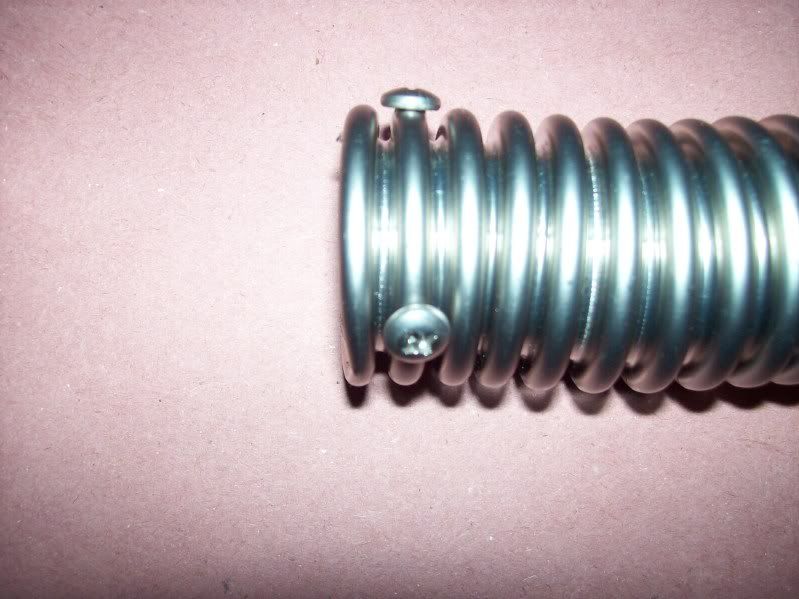
    Well done solution to the hose problem. You'll hear stories of the corrugated hose blowing off if you don't use multiple &/or special clamps. Here's my simple 50 cent method:


    Add 3 or 4 1/4" long stainless steel oval head sheet metal screws around the perimeter to create sort of a bead at the end of the corrugated hose. Once the coupler or hose is slipped over and the clamp (plain ol' garden variety worm screw type) is tightened it's not gonna' come off. I've done this on many without a single issue.

    I'll continue to follow along as you move forward and once again CONGRATS!

    Jeff

  26. #546
    Senior Member edwardb's Avatar
    Join Date
    Feb 2011
    Location
    Lake Orion, Michigan
    Posts
    10,577
    Post Thanks / Like
    Congratulations! Huge milestone. That Coyote is pretty amazing. Get it wired and it just runs. Way to go!
    Build 1: Mk3 Roadster #5125. Sold 11/08/2014. Build 2: Mk4 Roadster #7750. Sold 04/10/2017. Build Thread
    Build 3: Mk4 Roadster 20th Anniversary #8674. Sold 09/07/2020. Build Thread and Video. Build 4: Gen 3 Type 65 Coupe #59. Gen 3 Coyote. Legal 03/04/2020. Build Thread and Video
    Build 5: 35 Hot Rod Truck #138. LS3 and 4L65E auto. Rcvd 01/05/2021. Legal 04/20/2023. Build Thread. Sold 11/9/2023.

  27. #547
    2bking's Avatar
    Join Date
    Jul 2013
    Location
    Garland, Texas
    Posts
    799
    Post Thanks / Like
    Nothing sweeter than hearing the engine come to life when the start button is pushed. Congratulations! On the next start make sure the cooling fan comes on about 180. Mine hits about 190 on the dash gauge before the fan energizes.
    King
    Roadster #8127, ordered 7/12/13, received 9/11/13
    http://thefactoryfiveforum.com/showt...4-Coyote-Build

  28. #548
    Senior Member
    Join Date
    Oct 2016
    Location
    Fayetteville WV
    Posts
    256
    Post Thanks / Like
    Cool! Sounds great.
    1972 Corvette Stingray 350 c.i. Manual Steering & Brakes
    2003 H-D Softail Deuce 88 c.i. TwinCam
    Gen 3 Coupe Dreamer

  29. #549

    Steve >> aka: GoDadGo
    GoDadGo's Avatar
    Join Date
    Feb 2015
    Location
    Slidell, Louisiana
    Posts
    6,575
    Post Thanks / Like
    Blog Entries
    1
    Congratulations Jazzman!

    What A Great Milestone!

    Merry Christmas!

  30. #550
    Straversi's Avatar
    Join Date
    Nov 2014
    Location
    Palos Verdes, CA
    Posts
    1,278
    Post Thanks / Like
    Way to go Jazzman! How cool is that sound?
    -Steve
    Mk IV #8901 - Complete kit, Coyote, TKO-600, IRS. Ordered 5/23/16, Delivered 7/14/16, First Start 8/13/17, First Go-Kart 10/22/17, Registered and Completed 10/18/18. Build Thread: http://thefactoryfiveforum.com/showt...V-Coyote-Build Graduation Thread: https://thefactoryfiveforum.com/show...-Roadster-8901

  31. #551
    Senior Member cgundermann's Avatar
    Join Date
    Feb 2011
    Location
    Chino Valley, Arizona
    Posts
    1,077
    Post Thanks / Like
    Quote Originally Posted by Jeff Kleiner View Post
    Big, big congratulations on the milestone! I'm truly stoked for ya'

    Well done solution to the hose problem. You'll hear stories of the corrugated hose blowing off if you don't use multiple &/or special clamps. Here's my simple 50 cent method:


    Add 3 or 4 1/4" long stainless steel oval head sheet metal screws around the perimeter to create sort of a bead at the end of the corrugated hose. Once the coupler or hose is slipped over and the clamp (plain ol' garden variety worm screw type) is tightened it's not gonna' come off. I've done this on many without a single issue.

    I'll continue to follow along as you move forward and once again CONGRATS!

    Jeff
    Another great McGyver idea from Jeff!

  32. #552
    Jazzman's Avatar
    Join Date
    Jan 2014
    Location
    Scottsdale, AZ
    Posts
    1,164
    Post Thanks / Like
    An interesting couple of days. On Christmas Day I fired it up for my family. It immediately set off three cars alarms! They were all very impressed. I let it run for a while, and then it shut off on it's own. I started it right back up. Hmmm. I let it run long enough to confirm that the radiator fan comes on. It sounds lousy, but it sounds like it should. My F150 makes the same sound, and I hate it! Oh well, it works. YEAH!!

    I worked last night on connecting up the clock, the GPS keep alive circuit, the Volt meter, and reset the Tachometer so that it correctly reflected the right engine speed. (I think!). I know for sure it didn't idle at 150rpm, so I reset the Tach to register one revolution per pulse. This makes the gauge register about 600 rpm at idle after warmup.

    This morning I was going to work on the various relays that will drive the various lights and confirm that the engine will hook up with the transmission and drive the rear wheels. I went to fire up the engine, power shows up at the accessories position, pushed to start and . . . nothing. Silence. No fuel pump sound, no click from the engine at all. I checked all the fuses, all look good. I checked all the wires related to the ignition system, all look good. I checked grounds, again, all good. I checked the signal from RFID system to the starter when the button was pushed, and it was not sending a signal. I suspect an issue with the RFID system.

    I moved on to work on the relays, and didn't get very far because I had to go eat the worst Korean BBQ I have ever had!! When I came back home, I was just getting started when I had to turn on the power. This time I heard the fuel pump spool up. Just out of curiousity, I pressed the starter button. It fired right up! While I had it running, I decided to test the transmission connection. Yep, it all works. Engine hooks right up to the Tranny, goes into gear, shaft spins smoothly, rear wheels turn! Another success!! Just to be see what happened, I turned the car off (this time the starter button worked to shut it off) and turned it back on. It started right up. After it had been on for about a minute, it had a bit of hesitation in the idle, did it one more time, then settled in to a nice smooth idle again. No idea what that might be.

    I have decided I am going to follow EdwardB's lead and replace the clutch MC with a larger one in order to reduce effort. The clutch isn't as heavy as the one I had in my old mustang, but it sure isn't as light as I would like. (Now I have to go figure out which MC he ordered!! You would think by now I would have memorized EdwardB's thread!!)

    Now I am making up a punch list of things that have to be done before go-cart:
    1. Get steering wheel boss back from Russ Thompson. (he only got it today.)
    2. re-bleed brakes
    3. when the car is off the jack stands, re-torque the axel nuts.
    4. visually inspect brake lines to make sure there is no interference from moving wheel assemblies.
    5. Do a rudimentary alignment

    Anything else that i shouldn't forget?
    Jazzman

    MKIV #8745 "Flip Top" Roadster, Custom Tilt front, Coyote Engine, Tremec TKO600, Custom Interior. Best of Show winner, Huntington Beach Cruise In 2018.

    1967 Ford Mustang Coupe build thread updated 1/22/2021

    Roadster Frame Dolly Plan

  33. #553
    Senior Member edwardb's Avatar
    Join Date
    Feb 2011
    Location
    Lake Orion, Michigan
    Posts
    10,577
    Post Thanks / Like
    Quote Originally Posted by Jazzman View Post
    I know for sure it didn't idle at 150rpm, so I reset the Tach to register one revolution per pulse. This makes the gauge register about 600 rpm at idle after warmup.

    I have decided I am going to follow EdwardB's lead and replace the clutch MC with a larger one in order to reduce effort. The clutch isn't as heavy as the one I had in my old mustang, but it sure isn't as light as I would like.
    I'm assuming you have the Speedhut tach wire to one of the coil-over-plug harnesses? Like I showed in my build thread and others have done? Not sure how/why you would be getting a 600 rpm indication with that setting. The proper tach calibration is 1 pulse per 2 revolutions or 1/2 pulse per 1 revolution. Unless you have your Coyote running in 2-stroke mode. Mine starts at a little over 1,000 rpm, and then pretty quickly settles down into the 600-700 range. Also kind of smooths out a little. I'm guessing the PCM is adjusting the variable cams at that point, but don't know that for sure. Could be what you're noticing as hesitation.

    For the clutch MC, to reduce effort you need to go to a smaller diameter. That will also reduce the throw some (no free lunch...) so only consider the change if you can afford to lose some of the throw at the clutch arm. I'm assuming you have the 1-1/8 inch Wilwood master cylinder from Forte? I replaced mine with 260-10375 Wilwood 1 inch master cylinder kit from Summit Racing. It's like the one I received from Forte, just one size smaller. Comes with a couple extra parts (reservoir, etc.). I understand the MC only is available if ordered directly from Wilwood, but I didn't pursue it. No particularly expensive as the kit ($84) plus Summit had it on my doorstep the next day. Depends on what clutch you have, but likely it won't ever be as light as your old Mustang. Newer Mustangs have a spring assist, so they're even lighter. Won't be like that either.
    Last edited by edwardb; 12-27-2016 at 10:11 AM.
    Build 1: Mk3 Roadster #5125. Sold 11/08/2014. Build 2: Mk4 Roadster #7750. Sold 04/10/2017. Build Thread
    Build 3: Mk4 Roadster 20th Anniversary #8674. Sold 09/07/2020. Build Thread and Video. Build 4: Gen 3 Type 65 Coupe #59. Gen 3 Coyote. Legal 03/04/2020. Build Thread and Video
    Build 5: 35 Hot Rod Truck #138. LS3 and 4L65E auto. Rcvd 01/05/2021. Legal 04/20/2023. Build Thread. Sold 11/9/2023.

  34. #554
    Senior Member wareaglescott's Avatar
    Join Date
    Apr 2016
    Location
    Auburn, AL
    Posts
    2,146
    Post Thanks / Like
    Do you have a code reader that allows you to check for DTCs? Probably a good idea after a couple run cycles to hook one up and see if anything is showing up. That is also give you an idea if the MIL is functioning properly.
    MK4 #8900 - complete kit - Coyote, TKO600, IRS - Delivered 6/28/16 First Start 10/6/16 Go cart - 10/16/16 Build completed - 4/26/17 - 302 days to build my 302 CI Coyote Cobra - Registered and street legal 5/17/17
    Build Thread http://thefactoryfiveforum.com/showt...e-build-thread
    PHIL 4:13 INSTAGRAM - @scottsrides

  35. #555
    Senior Member MPTech's Avatar
    Join Date
    Feb 2011
    Location
    St. Louis, MO
    Posts
    1,187
    Post Thanks / Like
    Blog Entries
    8
    Congratulations on the first start!

    If you didn't use Jeff's suggestion (or something similar) on the corrugated SS hose, I highly recommend it, before it's too late. I thought I had the clamps pretty tight, but when it gets up to temp and builds pressure, it will blow them off and make a pretty good mess (and hopefully not burn you while you're driving!)
    F5R #7446: MK4, 302, T5 midshift, 3.55 Posi IRS, 17" Halibrands
    Delivered 4/4/11, First start 9/29/12, Licensed 4/24/13, off to PAINT 2/15/14!! Wahoo!

  36. #556
    Junior Member
    Join Date
    Jul 2013
    Posts
    8
    Post Thanks / Like
    Congrats - Sounds like a very good use of a Holiday weekend.

  37. #557
    Senior Member 2FAST4U's Avatar
    Join Date
    Feb 2011
    Posts
    1,006
    Post Thanks / Like
    Excellent job and congrats on the milestone.

  38. #558
    Member
    Join Date
    Jul 2016
    Location
    West Linn oregon
    Posts
    97
    Post Thanks / Like
    Nice work. I have enjoyed your build.

  39. #559
    Jazzman's Avatar
    Join Date
    Jan 2014
    Location
    Scottsdale, AZ
    Posts
    1,164
    Post Thanks / Like
    Thanks to all for the support!! Jeff's very valuable information came after I had already installed everything, so i do not have the little screws in the corrugated pipe. I will likely have to get in there and do it just so I won't be worrying about it!! Sincere thanks, Jeff, for your wise counsel.

    Interesting setback today. I spent an hour and half on the phone with Watson's Streetworks. They are really great with service after the sale. We talked through everything, tested several things, even verified the functionality of the RFID system if the car gets further than about 40 feet from me. That part works great. It shut down 45 seconds after the RFID chip was out of range. Pretty cool security feature!! However, we still could not pinpoint the reason the ignition system works most of the time, but not dependably all the time. Bottom line: they theorize that their current ignition module "backfeeds" with the 2016 Coyote system. (It works fine with the 2015 appearantly.) THey are going to go back to their engineer and have one part of their current system replaced and send me a customized box that should solve the problem. That will take about a week. In the interim, the car wont start because part of the testing was to cut two of the key wires that make the system work. (I could hook them back together, but then I would have to cut them again to put in the new Ignition module box.) So for this week, the car is silent again.
    Jazzman

    MKIV #8745 "Flip Top" Roadster, Custom Tilt front, Coyote Engine, Tremec TKO600, Custom Interior. Best of Show winner, Huntington Beach Cruise In 2018.

    1967 Ford Mustang Coupe build thread updated 1/22/2021

    Roadster Frame Dolly Plan

  40. #560

    Join Date
    Nov 2016
    Location
    "The i.e." SoCal
    Posts
    763
    Post Thanks / Like
    Quote Originally Posted by Jazzman View Post
    IT's ALIVE!! I am so excited!!
    Congrats Kevin! One more step closer.

    BTW. Your roll bars go to the machine shop this week, sorry for the delay.

    i.e.427

Page 14 of 28 FirstFirst ... 4121314151624 ... LastLast

Posting Permissions

  • You may not post new threads
  • You may not post replies
  • You may not post attachments
  • You may not edit your posts
  •  

Replica Parts

Visit our community sponsor